Table of Contents
Advertisement
ORTEC
®
™
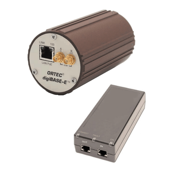
digiBASE-E
High-Performance, Power-over-Ethernet
Multichannel Analyzer / PMT Base
for Scintillation Detectors
User's Manual
NOTICE OF PROPRIETARY PROPERTY
This document and the information contained in it are the proprietary property
of AMETEK Inc., ORTEC Business Unit. It may not be copied or used in any
manner nor may any of the information in or upon it be used for any purpose
without the express written consent of an authorized agent of AMETEK Inc.,
ORTEC Business Unit.
Printed in U.S.A.
ORTEC Part No. 931047
0213
Manual Revision C
Advertisement
Table of Contents

Related Manuals for ORTEC digiBASE-E


Summary of Contents for ORTEC digiBASE-E
- Page 1 This document and the information contained in it are the proprietary property of AMETEK Inc., ORTEC Business Unit. It may not be copied or used in any manner nor may any of the information in or upon it be used for any purpose without the express written consent of an authorized agent of AMETEK Inc.,...
-
Page 2: Warranty
If it becomes necessary to return this instrument for repair, it is essential that Customer Services be contacted in advance of its return so that a Return Authorization Number can be assigned to the unit. Also, ORTEC must be informed, either in writing, by telephone [(865) 482-4411] or by facsimile transmission [(865) 483-2133], of the nature of the fault of the instrument being returned and of the model, serial, and revision ("Rev"... -
Page 3: Table Of Contents
3. USING THE DIGIBASE-E ..........17 3.1. digiBASE-E MCB Properties in MAESTRO ....... . 17... - Page 4 ™ High-Performance Power-over-Ethernet Multichannel Analyzer / PMT Base for Scintillation Detectors 3.1.1. Amplifier ............17 3.1.2.
-
Page 5: Safety Instructions And Symbols
Safety Instructions and Symbols This manual contains up to three levels of safety instructions that must be observed in order to avoid personal injury and/or damage to equipment or other property. These are: DANGER Indicates a hazard that could result in death or serious bodily harm if the safety instruction is not observed. -
Page 7: Introduction
The digiBASE-E can be used with numerous scintillators. NaI(Tl) detectors have been histor- ically the most popular; but with its new trapezoidal digital filter, the digiBASE-E is also com- patible with the newer, faster scintillators, such as LaBr3(Ce). The digiBASE-E has almost three ®... -
Page 8: Flexible Gating
™ High-Performance Power-over-Ethernet Multichannel Analyzer / PMT Base for Scintillation Detectors In addition to PHA and List modes, an external input allows the digiBASE-E to perform as a 32-bit counter for low-voltage TTL (LVTTL) pulses. The counter can be read through the MAESTRO MCA emulation software or user-created software. -
Page 9: Host Pc And Software Requirements
Complete details on using the control software are in the MAESTRO Software User’s Manual as well as the manuals for ScintiVision-32 and our other ORTEC software applications. For the purposes of this manual, when we refer to MAESTRO, we mean the ORTEC MCA emulator/analysis application you are using (e.g., MAESTRO, ScintiVision-32). - Page 10 ™ High-Performance Power-over-Ethernet Multichannel Analyzer / PMT Base for Scintillation Detectors...
-
Page 11: Getting Started
2. GETTING STARTED 2.1. The digiBASE-E Figure 1 shows the digiBASE-E connectors on both the top and bottom panels, including the pin assignments for the socket base, which accepts JEDEC B14-38 PMT pin bases (Table 1). The digiBASE-E operates on Power over Ethernet (PoE). The CAT5E Ethernet cable runs to a single-port PoE injector that requires an ac power source (see the specifications in Chapter 4). - Page 12 ™ High-Performance Power-over-Ethernet Multichannel Analyzer / PMT Base for Scintillation Detectors The gate input can accept multiple signal types, which you can select from the ADC property page in MAESTRO (supplied) or from a customer-written program (command syntax is described in Chapter 5).
-
Page 13: Software And Hardware Installation
2. If using ScintiVision-32, install it before installing MAESTRO. 3. Install the accompanying MAESTRO MCA Emulation Software (A65-BW). 4. Set the digiBASE-E’s coarse gain jumper as desired (the factory default is 1×), then mount the detector on the digiBASE-E. 5. Connect the single-port PoE injector to an ac power supply 6. - Page 14 ™ High-Performance Power-over-Ethernet Multichannel Analyzer / PMT Base for Scintillation Detectors Figure 2. Installation Quick-Reference.
-
Page 15: Step 1: Install The Connections Driver Update Kit
2.3.3. Steps 4 through 7: Hardware Setup and Installation 4. The coarse gain for the digiBASE-E is set with a jumper on the analog board. The available settings are 1×, 3×, and 9×; the factory default is 1×. If you wish to use a different setting, see the instructions in Appendix A. -
Page 16: Step 8: Use The Devicecontroller Program To "Attach" To The Digibase-E
In most cases, there will be no need to change your firewall settings. The digiBASE-E is supplied with two 10 ft (3 m) CAT5E Ethernet cables. Attach one CAT5E cable to the IN (LAN) jack of the PoE injector, then connect it to the PC’s Ethernet adaptor or to the LAN. - Page 17 This is unlike other ORTEC MCAs, which (if powered on) are displayed by the MCB Configuration program even if they are not attached to your local PC. Most ORTEC MCAs use only the MCB Configuration program to set up communication with your PC. The digiBASE-E communicates differently than other ORTEC instruments;...
-
Page 18: Ip Addressing - Dynamic Vs. Static
We recommend using the DHCP option, where available, because it is simplest and least prone to address incompatibility issues. If you connect one or more powered-on digiBASE-Es to a network with a DHCP server, it will assign each digiBASE-E a dynamic IP address. Then when... -
Page 19: Static
The digiBASE-E is factory-assigned the static IP address 169.254.0.127. If you connect a new digiBASE-E to a PC that does not have network access, this is the IP address you will see the first time you run the accompanying digiBASE-E Ethernet Device Controller program. Note that it can take 5 or more minutes for the PC and digiBASE-E to establish communication. -
Page 20: Lease Time For Ip Addresses
Lease Time for IP Addresses The digiBASE-E will retain a dynamic IP address as long as it remains connected to the network and powered on via an IEEE 802.3af device, or for the length of the IP address lease (an adjustable property of the DHCP server). -
Page 21: Configuring A New Instrument
MCBs and their ORTEC software, for instance, if they control their MCBs with files (e.g., the file command .JOB .JOB SET_DETECTOR 5 ® or use the ORTEC GammaVision or ISOTOPIC spectroscopy applications. If this is a first-time installation of ORTEC products, all your instruments will be “new.”... -
Page 22: Multiple Users Can Attach To The Same Digibase-E
(see also the IMPORTANT note on page 10). However, if moving a digiBASE-E with a manually assigned (static) IP address to a network or PC with a different subnet address, be sure to do the following to avoid IP address incompatibilities: Before disconnecting from the current PC or network, re-run the Ethernet Device Controller program. -
Page 23: Using The Digibase-E
MCB Properties... command under the Acquire ONNECTIONS menu. The digiBASE-E is completely software controlled; the MCB Properties dialog contains all of the instrument controls including ADC setup parameters, acquisition presets, high voltage, the gain and zero stabilizers, and amplifier gain adjustments. Just move from tab to tab and set your hardware parameters, then click on Close. -
Page 24: Amplifier 2
40 ns steps. The dead time per pulse is For the more advanced user, the InSight mode allows you to directly the digiBASE-E’s advanced shaping parameters and adjust them interactively while collecting live data. To access the InSight mode, click on Start, then refer to the discussion in the MAESTRO User’s Manual. -
Page 25: Gate
This level establishes an upper-level cutoff by channel number for storage. 3.1.3.1. Gate Figure 10. digiBASE-E ADC Tab. The digiBASE-E supports eight gate modes, but only six are useful within MAESTRO and ScintiVision (the others require customer-written software). -
Page 26: Stabilizer
™ High-Performance Power-over-Ethernet Multichannel Analyzer / PMT Base for Scintillation Detectors 3.1.4. Stabilizer The digiBASE-E has both a gain stabilizer and a zero stabilizer; their operation is discussed in more detail in the MAESTRO User’s Manual. The Stabilizer tab (Fig. 11) shows the current values for the stabilizers. -
Page 27: High Voltage
Target field, click On, and monitor the voltage in the Actual field. Click the Off button to turn off the high voltage. Figure 12. digiBASE-E High Voltage Tab. 3.1.6. About This tab (Fig. 13) displays hardware and firmware information about the... -
Page 28: Status
™ High-Performance Power-over-Ethernet Multichannel Analyzer / PMT Base for Scintillation Detectors 3.1.7. Status Figure 14 shows the Status tab. The 32-bit Event Counter functions when the Gate function on the ADC tab is set to EventCounter and the digiBASE-E is actively acquiring data in a spectrum. -
Page 29: Troubleshooting
3.2.1. Connection Failed / Socket Error (Incompatible Static IP Address) If you move a digiBASE-E with a static IP address to a different network or PC without following the instructions in Section 2.5, the IP address currently assigned to the digiBASE-E could be incompatible with the new network or PC. - Page 30 Set the first two bytes (dot address sections) of the IP address and the Subnet mask to the values you recorded for the digiBASE-E; see the circled portions of Fig. 18. Click on OK. Re-run the Ethernet Device Controller program. It should now locate the digiBASE-E and...
- Page 31 3. USING THE DIGIBASE-E Click to highlight the digiBASE-E. If you will be using the new network’s DHCP server to assign an IP address, simply mark the DHCP checkbox, click on Save, and close the device controller program window. If manually setting the IP address, leave the DHCP box unmarked, enter an IP address compatible with the new network, Save, and close the device controller program window.
-
Page 32: Cannot Communicate With Maestro Or Scintivision-32
Re-run the Ethernet Device Controller software, click the Find All digiBASE-Es button, and make sure the program locates the digiBASE-E by serial number. If the IP address lease has expired, this will assign a new IP address. If the device controller program generates a connection failure and/or socket error for this digiBASE-E and fails to display the serial number, the instrument’s current IP address is incompatible with the network;... -
Page 33: Specifications
Real Time Up to 8.5×10 seconds in steps of 20 ms. Spectrum Stabilizer The digiBASE-E features built-in gain and offset stabilization circuitry. Stabilization is performed by providing a reference peak in the spectrum, which the MCA can monitor, should drift be detected, the gain and offset of the system are adjusted automatically to correct for the drift. -
Page 34: Inputs
(1 in. × 1 in.) crystals on 1.5 in. PMTs, and 8-stage (as opposed to 10-stage), 14-pin bases on 2 in. and 3 in. PMTs for the larger crystal sizes. If required, compatibility can be achieved through the use of adaptors. Contact ORTEC or your detector vendor for more information. 4.4. Computer Controls and Indicators All controls and readouts are implemented in the MAESTRO MCA Emulation Software included with the digiBASE-E. -
Page 35: Electrical, Mechanical, And Environmental
4.6. Feature Mask Bits The following table describes the feature bits from the SHOW_FEATURES command discussed on page 50. If the feature is supported in the digiBASE-E, the bit is set to 1; if the feature is not supported, the bit is 0. - Page 36 ™ High-Performance Power-over-Ethernet Multichannel Analyzer / PMT Base for Scintillation Detectors Meaning Sample mode functions available Digital Offset (e.g., 920) Software-selectable analog offset HV power supply Enhanced HV (SET_HV, SET/SHOW_HV_POL, SHOW_HV_ACT) Software-selectable HV range (ENA_NAI, DIS_NAI) Auto PZ (START_PZ_AUTO)
- Page 37 4. SPECIFICATIONS Meaning Software-selectable MCS-mode input sources Uncertainty/statistical preset (SET_UNCERT_PRES) Features vary by input (SHOW_FEATURES depends on device/segment;multi-input MCBs only) Software-selectable HV shutdown mode (SET/SHOW/VERI_SHUT) Software-selectable shaping time constants (SET_SHAP) Explorable shaping time constants (SHOW_CONFIG_SHAP) Advanced shaping time (SET_SHAP_RISE, SET_SHAPE_FLAT, etc.) Software-selectable BLR (ENA/DIS/SHO_BLR_AUTO SET/SHO/VERI_BLR) SHOW_STATUS command supported (returns $M record) Overflow preset (ENA/DIS/SHO_OVER_PRES)
- Page 38 ™ High-Performance Power-over-Ethernet Multichannel Analyzer / PMT Base for Scintillation Detectors Meaning Has programmable external dwell voltage capability No Peak Preset feature (M CA and OASIS) Programmable pulser (OASIS) Programmable Vacuum/HV interlock (OASIS) Programmable Current/HV interlock (OASIS) 0 Explorable Stabilizer (LIST_GAIN_ADJU, LIST_ZERO_ADJU)
- Page 39 4. SPECIFICATIONS Meaning ID Reports (DO_ID, SHOW_REPORT, SHOW_REPO_LINES) Has Neutron Detector (SHOW_CRM 2 returns valid number) List Mode data streamed and formatted like DIGIBase-E...
- Page 40 ™ High-Performance Power-over-Ethernet Multichannel Analyzer / PMT Base for Scintillation Detectors...
-
Page 41: Firmware Commands And Responses
5. FIRMWARE COMMANDS AND RESPONSES Software communication with the digiBASE-E takes place through the C software ONNECTIONS layer. Connections is used by all ORTEC software, and the C Programmer’s Toolkit ONNECTIONS (A11-B32) is available for other software development. 5.1. C... -
Page 42: Percent Response Records
The macro error code represents the general class of error with 0 meaning no error, and the micro error code represents the sub-class of error with 0 meaning no error. Following is a list of all percent responses for the digiBASE-E: Unconditional Success: %000000069<CR>... - Page 43 5. FIRMWARE COMMANDS AND RESPONSES %000053077<CR> Device already started, high voltage not enabled and amplifier was not pole-zeroed. The command was ignored. %000038080<CR> Device preset already exceeded and high voltage not enabled. The command was ignored. %000054078<CR> Device preset already exceeded, high voltage not enabled and amplifier was not pole-zeroed.
-
Page 44: Dollar Response Records
™ High-Performance Power-over-Ethernet Multichannel Analyzer / PMT Base for Scintillation Detectors 5.1.3. Dollar Response Records SHOW and STEP commands respond with a single dollar response record followed immediately by a percent response record. All valid dollar response records for each command are listed in the command dictionary. - Page 45 5. FIRMWARE COMMANDS AND RESPONSES alphanumeric character strings rather than numerical values. Items in the command prototype that are surrounded by square brackets “[...]” are optional items and are not always required. In this section the term <CR> represents the ASCII carriage return character, decimal value 13, and the character “_”...
- Page 46 Enables the stabilization of the gain peak. See also DISABLE_GAIN_STABILIZATION, SHOW_GAIN_STABILIZATION, and INITIALIZE_GAIN_STABILIZATION. ENAB_HV Turns on the high-voltage enable output of the digiBASE-E and sets the HV to the target HV value. See also DISABLE_HV and SHOW_HV. Execution Errors: %131137085<CR>...
- Page 47 5. FIRMWARE COMMANDS AND RESPONSES ENABLE_REMOTE No function in the digiBASE-E . This command has been included for backward compatibility. ENABLE_THRESHOLD_AUTOMATIC Enables automatic determination of the positive and negative thresholds. See also DISABLE_THRESHOLD_AUTO, SHOW_THRESHOLD_AUTO, SET_THRESHOLD_NEGATIVE, and SET_THRESHOLD_POSITIVE. ENABLE_THRESHOLD_SAMPLE ENABLE_TRIGGER_SPECIAL No function; included for backward compatibility.
- Page 48 256, 512, 1024, or 2048 channels. Response: GAIN_CONV 256 512 1024 2048 LIST_GAIN_FINE Lists the valid fine-gain settings. digiBASE-E has a fine gain range between 0.33 and 1.00. Response: GAIN_FINE 0.33 1.00 2097152 6291456 LIST_GATE Lists the available gate modes for the digiBASE-E.
- Page 49 (see SET_WINDOW command) to the specified value. ROI flags are not affected. SET_DATA_APPLICATION “string1",”string2" This is used to store information in the digiBASE-E internal memory that can be used by other programs, such as sample descriptions and energy calibrations. C makes ONNECTIONS use of this feature.
- Page 50 ™ High-Performance Power-over-Ethernet Multichannel Analyzer / PMT Base for Scintillation Detectors SET_GAIN_ADJUSTMENT value Sets the gain stabilization adjustment to an arbitrary value from !65535 to 65535. This adjustment is usually made only by the gain stabilizer, and reset to 0 with the INITIALIZE_GAIN_STABILIZATION command.
- Page 51 SET_LIVE ticks Sets the live-time counter to the specified number of ticks. The number represents live time in units of 20 ms (50 ticks/s). Normally this value is set by the digiBASE-E during data acquisition. See also CLEAR_COUNTERS and SHOW_LIVE.
- Page 52 SET_OUTPUT_LOW. See also SHOW_OUTPUT. See also STEP_OUTPUT. SET_OUTPUT_HIGH [output-num] Sets the Change Sample output to the high level. The digiBASE-E has only one sample- changer BNC, therefore, if you include a value for output-num, it must be zero (output-num is provided for compatibility with other ORTEC instruments). See also STEP_OUTPUT.
- Page 53 SET_TRUE ticks Sets the true-time counter to the specified number of ticks. The number represents true time in units of 20 ms (50 ticks/sec). Normally this value is set by the digiBASE-E during data acquisition. See also CLEAR_COUNTERS and SHOW_TRUE.
- Page 54 (SET_VIEW 0) and the alternative histogram memory (SET_VIEW 1). Note that this command affects only the spectrum view for the local PC. Users attached to this digiBASE-E via other network nodes will, by default, see the regular histogram memory data in MAESTRO.
- Page 55 %131136084<CR> The command was attempted while zero stabilization was enabled. SHOW_ACTIVE Returns a 1 if the digiBASE-E is active (i.e., acquiring spectral data) or 0 if it is not active. Responses: $C00000087<CR> Not active. $C00001088<CR> Active.
- Page 56 ™ High-Performance Power-over-Ethernet Multichannel Analyzer / PMT Base for Scintillation Detectors SHOW_CONFIGURATION_MASK Returns two masks, the first of which can be “anded” with data from the MCB to clear the ROI bit from the data. When the second mask value is “anded” with data from the MCB, the data bits are removed and only the ROI bit remains.
- Page 57 Gain channel is channel 2 (lowest possible channel). $C00250094<CR> Gain channel is channel 250. SHOW_GAIN_CONVERSION This command returns the conversion gain for the digiBASE-E, which can be 256, 512, 1024, or 2048 channels. Responses: $C02048101<CR> Conversion gain reported as 2048 channels.
- Page 58 $D0100000007082<CR> 1000 V, negative, not overloaded, enabled. SHOW_HV_ACTUAL Returns the value of HV actually on the detector. SHOW_HV_POLARITY This returns the HV polarity setting as a $F record (always positive for the digiBASE-E). Response: $IPOS<CR> The HV is positive. SHOW_HV_TARGET Under normal operation, the HV will go to this value when the HV is enabled.
- Page 59 5. FIRMWARE COMMANDS AND RESPONSES Bit 0 (LSB): Bias supply polarity (0=positive, 1=negative). Bit 1: Bias supply overload (0=overload, 1=normal). Bit 2: HV enabled (0=disabled, 1=enabled). Example Responses: $D0100000003077<CR> 1000 V, negative, not overloaded, disabled. $D0100000002076<CR> 1000 V, positive, not overloaded, disabled. $D0100000007082<CR>...
- Page 60 Returns with an ASCII string label designation for the state-of-health parameter for num. SHOW_MONI_MAX Returns with the number of monitors available for viewing. SHOW_MONI_VALUE num Returns with an ASCII representation of the value for the monitor. For the digiBASE-E, SHOW_MONI_VALUE 0 returns the 32-bit event counter value.
- Page 61 Indicates whether MCB is in NaI Mode. Responses are true and false. Responses: $IT<CR> digiBASE-E is always in NaI mode. SHOW_NEXT Used in conjunction with the SHOW_ROI command, SHOW_NEXT reports the next continuous group of channels that have the ROI flag set. The response is of the form $Dsssssnnnnnccc<CR>...
- Page 62 ™ High-Performance Power-over-Ethernet Multichannel Analyzer / PMT Base for Scintillation Detectors SHOW_PEAK_CHANNEL This command returns the number of the ROI channel with the largest number of counts. An ROI channel is a channel that has the ROI flag set. The lowest number ROI channel with the largest count is reported if more that one channel contains the largest number of counts.
- Page 63 Displays the rise-time setting in μs. See also SET_SHAP_RISE. Responses: Rise time setting 0.64 μs. SHAP_RISE 000000000000.64 SHOW_SNUM Responds with a $F record indicating the serial number of the digiBASE-E. Response: $F100 Serial number 100. SHOW_STATUS Returns system status information in the following format: $Mllllllllllttttttttttaaaaahhhhhccc<CR>...
- Page 64 ™ High-Performance Power-over-Ethernet Multichannel Analyzer / PMT Base for Scintillation Detectors SHOW_TRUE Reports the contents of the true-time counter in units of 20 ms (50 ticks/s). See also CLEAR_COUNTERS and SET_TRUE. Responses: $G0000000000075<CR> True time reported as 0 ticks.
- Page 65 5. FIRMWARE COMMANDS AND RESPONSES SHOW_VERS_LOGIC Lists the FPGA firmware version. Response: $FFPGA version=32771 SHOW_WINDOW Reports the start channel and number of channels in the window of interest, in the form $Dxxxxxyyyyyccc<CR> where xxxxx is the start channel (0 to [conversion gain ! 1]) and yyyyy is the number of channels (1 to [conversion gain]).
- Page 66 Initial and final level on Change Sample was high. STOP [seg-mask] Stops the data acquisition. The optional segment mask is provided for compatibility with other MCBs and may be any value from 0 to 65535 but is ignored by the digiBASE-E. Execution Warnings: %000005074...
-
Page 67: Appendix A. Setting The Coarse Gain Jumper
APPENDIX A. SETTING THE COARSE GAIN JUMPER The digiBASE has 3 coarse gain settings, 1×, 3×, and 9×, determined by setting a jumper within the unit. the factory setting is 1×. To change the coarse gain: DANGER HIGH VOLTAGES are present on the tube socket and inside the unit. Never operate the digiBASE with the shroud removed or without a detector installed on the socket. - Page 68 ™ High-Performance Power-over-Ethernet Multichannel Analyzer / PMT Base for Scintillation Detectors Replace the washer and nut on the A INPUT and B OUTPUT connectors. Note the new coarse gain setting for this unit. There is no software-based way to read this setting (i.e., you must remove the shroud and inspect the jumper if you are unsure of the...
-
Page 69: Appendix B. List Mode
IP addresses. You can also contact your ORTEC representative or our Global Service Center to obtain sample C++ code showing how to start list mode acquisition, retrieve raw data from the digiBASE-E, save the data to disk, and parse the raw data. - Page 70 = Realtime[12:0],Prescale[17:1]; note that these are two separate entities, not a single number. This sync pulse is a time-stamp sync. Because each digiBASE-E uses its own internal clock, when operating multiple digiBASE-Es together, they tend to diverge. The sync pulse is used to correct the divergence.
-
Page 71: Index
InSight Mode ......18 Attach to digiBASE-E ....10 mark types . - Page 72 ™ High-Performance Power-over-Ethernet Multichannel Analyzer / PMT Base for Scintillation Detectors...
Need help?
Do you have a question about the digiBASE-E and is the answer not in the manual?
Questions and answers