
Related Manuals for Allen-Bradley 1732ES-IB16


Summary of Contents for Allen-Bradley 1732ES-IB16
- Page 1 User Manual Original Instructions Guard I/O EtherNet/IP Safety Modules Catalog Numbers 1732ES-IB16, 1732ES-IB8XOB8, 1732ES-IB8XOBV4, 1732ES-IB12XOB4, 1732ES-IB12XOBV2, 1791ES-IB16, 1791ES-IB8XOBV4...
- Page 2 Important User Information Read this document and the documents listed in the additional resources section about installation, configuration, and operation of this equipment before you install, configure, operate, or maintain this product. Users are required to familiarize themselves with installation and wiring instructions in addition to requirements of all applicable codes, laws, and standards.
-
Page 3: Table Of Contents
Table of Contents Summary of Changes ..........7 Preface . - Page 4 Table of Contents Chapter 3 Install the Module Environment and Enclosure........39 For 1791ES Modules .
- Page 5 1732ES-IB12XOBV2 Modules ......117 1732ES-IB16 Modules ........122 1732ES-IBXOB8 Modules .
- Page 6 Table of Contents Notes: Rockwell Automation Publication 1791ES-UM001G-EN-P - November 2016...
-
Page 7: Summary Of Changes
Added publications to the Additional Resources section. Updated Attention statement. Added the following catalog numbers to Table 1: 1732ES-IB16, 1732ES-IB8XOB8, and 1756-IBXOBV4. Deleted the About the Catalog Numbers section. Updated the Programming Requirements section with catalog numbers and RSLogix 5000® versions. - Page 8 Summary of Changes Notes: Rockwell Automation Publication 1791ES-UM001G-EN-P - November 2016...
-
Page 9: Preface
Preface About the Specifications and Product specifications and accessories can change at any time based on improvements and other reasons. Consult with your Rockwell Automation Dimensions in This Manual representative to confirm actual specifications of purchased product. Dimensions and weights are nominal and are not for use for manufacturing purposes, even when tolerances are shown. -
Page 10: Additional Resources
Additional Resources These documents contain additional information concerning related products from Rockwell Automation. Resource Description Allen-Bradley® Stratix® 5700 Network Address Translation (NAT) White Paper, Provides information about NAT. publication ENET-WP032 ArmorBlock Guard I/O EtherNet/IP Safety Modules Product Information, Provides instructions to install ArmorBlock Guard I/O EtherNet/IP Safety modules. -
Page 11: Safety Function Operation
Chapter Safety Function Operation Topic Page Safe State Self-diagnostic Functions Configuration Lock I/O Status Data Safety Inputs Muting Lamp Operation Safety Outputs Controlling Devices Read this chapter for information related to the safety functions of the modules. Also included is a brief overview on international standards and directives that you must be familiar with. -
Page 12: Self-Diagnostic Functions
Chapter 1 Safety Function Operation The module is designed for use in applications where the safety state is the off state. Self-diagnostic Functions Self-diagnostics are performed when the power is turned on and periodically during operation. If a fatal internal module error occurs, the red module status (MS) indicator illuminates, and the safety outputs and input data and status to the network turn off. -
Page 13: Safety Inputs
Safety Function Operation Chapter 1 Safety Inputs Read this section for information about safety inputs and their associated test outputs. A safety input can be used with test outputs. Safety inputs are used to monitor safety input devices. Using a Test Output with a Safety Input A test output can be used in combination with a safety input for short circuit detection. - Page 14 Chapter 1 Safety Function Operation Table 1 - Typical Pulse Width and Period Pulse Width Period 500 μs 150 ms Figure 3 - Test Pulse in a Cycle Typical Typical 500 μs 150 ms ATTENTION: Do not use test outputs as safety outputs. Test outputs do not function as safety outputs.
- Page 15 Safety Function Operation Chapter 1 When the external input contact is closed, a test pulse is output from the test output terminal to diagnose the field wiring and input circuitry. By using this function, short circuits between input signal lines and the power supply (positive side), and short circuits between input signal lines can be detected.
- Page 16 Chapter 1 Safety Function Operation If an error is detected, safety input data and safety input status turns off. Figure 5 - Single Channel Normal Operation and Fault Detection (not to scale) Normal Operation External Device Input Terminal 0 Safety Input 0 Remote Data Safety Input...
-
Page 17: Set Dual-Channel Mode And Discrepancy Time
Safety Function Operation Chapter 1 Set Dual-channel Mode and Discrepancy Time To support redundant channel safety devices, the consistency between signals on two channels can be evaluated. Either equivalent or complementary can be selected. This function monitors the time during which there is a discrepancy between the two channels. - Page 18 Chapter 1 Safety Function Operation occur before the discrepancy time elapses, the channels fault. In the fault state, the input and status for both channels are set low (off ). When configured as an equivalent dual pair, the data bits for both channels are sent to the controller as equivalent, both high or both low.
-
Page 19: Dual-Channels, Complementary
Safety Function Operation Chapter 1 Dual-channels, Complementary In Complementary mode, the inputs of a pair are typically in the opposite (complementary) state. When a transition occurs in one channel of the pair before the transition of the second channel of the pair, a discrepancy occurs. If the second channel transitions to the appropriate state before the discrepancy time elapses, the inputs are considered complementary. -
Page 20: Safety Input Fault Recovery
Chapter 1 Safety Function Operation Safety Input Fault Recovery If an error is detected, the safety input data remains in the off state. Follow this procedure to activate the safety input data. 1. Remove the cause of the error. 2. Place the safety input (or safety inputs) into the safety state. The safety input status turns on (fault cleared) after the input-error latch time has elapsed. -
Page 21: Muting Lamp Operation
1732ES-IB8XOB8 • T3, T7, and T11 for 1732ES-IB12XOB4 and 1732ES-IB12XOBV2 • T3, T7, T11, and T15 for 1791ES-IB16 and 1732ES-IB16 Muting lamp status is monitored with a test that runs periodically during every test interval to detect a burned-out lamp. The test runs repeatedly when the test output is commanded on. - Page 22 Chapter 1 Safety Function Operation Table 3 shows the expected behavior of the muting status bits. Keep these points in mind as well: • When power is applied to the module, and a test output capable of operating as a muting output remains commanded off, the muting status defaults to on.
-
Page 23: Safety Outputs
Safety Function Operation Chapter 1 Safety Outputs Read this section for information about safety outputs. ATTENTION: Serious injury can occur due to the breakdown of safety outputs. Do not connect loads beyond the rated value to the safety outputs. Safety Output with Test Pulse When the safety output is on, the safety output can be test pulsed, as shown in Table 4 Figure... -
Page 24: Dual-Channel
Chapter 1 Safety Function Operation Dual-channel When the data of both channels is in the on state, and neither channel has a fault, the outputs are turned on. The status is normal. If a fault is detected on one channel, the safety output data and individual safety output status turn off for both channels. -
Page 25: Single-Channel
Safety Function Operation Chapter 1 Single-channel When the data of the channel is in the on state, and the channel does not have a fault, the output is turned on. The status is normal. If a fault is detected on the channel, the safety output data and individual safety output status turn off for the channel. -
Page 26: Controlling Devices
Device Requirements table. Serious injury can occur due to loss of safety functions. Table 5 - Controlling Device Requirements Device Requirement Allen-Bradley® Bulletin Safety Components Emergency stop switches Use approved devices with direct opening mechanisms that comply with Bulletin 800F, 800T IEC/EN 60947-5-1. -
Page 27: About The Modules
Chapter About the Modules Topic Page Before You Begin Firmware Information and Downloads Functional Safety Certificates Understand Suitability for Use Follow Precautions for Use I/O Module Overview 1791ES-IB16 and 1791ES-IB8XOBV4 Modules North American Hazardous Location Approval Selecting a Power Supply Programming Requirements CIP Safety in EtherNet/IP Safety Architectures Identify Major Parts of the Module... -
Page 28: Firmware Information And Downloads
Chapter 2 About the Modules Firmware Information and Verify that the Guard I/O firmware revision is correct before you commission the safety system. Firmware information and downloads for safety modules are Downloads available at this link: http://www.rockwellautomation.com/rockwellautomation/support/ pcdc.page. Functional Safety Safety certificates for Functional Safety modules are available at this link: http://www.rockwellautomation.com/global/certification/overview.page Certificates... -
Page 29: 1791Es-Ib16 And 1791Es-Ib8Xobv4 Modules North American Hazardous Location
About the Modules Chapter 2 1791ES-IB16 and The following information applies when operating this equipment in hazardous locations: Products marked “CL I, DIV 2, GP A, B, C, D” are suitable for use in Class I Division 2 Groups 1791ES-IB8XOBV4 Modules A, B, C, D, Hazardous Locations and nonhazardous locations only. -
Page 30: Follow Precautions For Use
Chapter 2 About the Modules Follow Precautions for Use Follow the precautions for use listed here and throughout this manual. ATTENTION: Follow Safety Standards for Installation and Testing • Use only appropriate components or devices complying with relevant safety standards corresponding to the required safety category and safety integrity level: •... -
Page 31: I/O Module Overview
About the Modules Chapter 2 I/O Module Overview The Guard I/O modules implement the CIP Safety™ protocol extensions over EtherNet/IP networks and provide various features for a safety system. Use the modules to construct a safety-control network system that meets the following requirements, up to and including: •... - Page 32 Chapter 2 About the Modules The following is a list of features common to Guard I/O modules: • CIP Safety and EtherNet/IP protocol conformance • Safety inputs – Safety devices, such as emergency stop push buttons, gate switches, and safety light curtains, can be connected. –...
-
Page 33: Selecting A Power Supply
ArmorBlock® safety I/O module with solid-state outputs Meets IP65/IP67 4 sourcing outputs (when marked) 1732ES-IB12XOBV2 ArmorBlock safety I/O module with solid-state outputs 4 bipolar outputs (2 pairs) 1732ES-IB16 ArmorBlock safety input module Meets IP65/IP67 — (when marked) 1732ES-IB8XOB8 ArmorBlock safety I/O module with solid-state outputs... -
Page 34: Programming Requirements
Designer® Version (EtherNet/IP Network) 1791ES-IB16 1791ES-IB8XOBV4 1732ES-IB12XOB4 1732ES-IB12XOBV2 1732ES-IB16 1732ES-IB8XOB8 1732ES-IB8XOBV4 (1) This version or later. CIP Safety in Safety controllers control the safety outputs. Safety or standard controllers can control the standard outputs. Use Guard I/O modules in EtherNet/IP safety... -
Page 35: Device Level Ring (Dlr)
About the Modules Chapter 2 Device Level Ring (DLR) A DLR network is a single-fault-tolerant ring network that is intended for the interconnection of automation devices without the need for more switches. The ring topology offers these advantages: • Media redundancy •... - Page 36 Chapter 2 About the Modules A DLR network includes the following nodes. Node Description Supervisor node A DLR network requires at least one node to be configured as ring supervisor. IMPORTANT: By default, the supervisor function is disabled on supervisor-capable devices, so they are ready to participate in a linear/star network or as a ring node on a DLR network.
-
Page 37: Identify Major Parts Of The Module
About the Modules Chapter 2 Identify Major Parts of the Figure 16 Figure 17 for module identification. See Chapter 3 pinout information. Module Figure 16 - 1791ES Module Connections and Indicators Power Connector I/O Connectors Status Indicators Network Activity Indicator EtherNet/IP Connector EtherNet/IP Address... - Page 38 Chapter 2 About the Modules Notes: Rockwell Automation Publication 1791ES-UM001G-EN-P - November 2016...
-
Page 39: Environment And Enclosure
Chapter Install the Module Topic Page Environment and Enclosure Prevent Electrostatic Discharge Environmental Considerations for Use Follow Wiring Precautions Follow DC Power Supply Precautions Mount the Module Make Connections for 1791ES Modules Make Connections for 1732ES Modules Read and understand this section before you begin to install the module. Environment and Enclosure For 1791ES Modules ATTENTION: This equipment is intended for use in a Pollution Degree 2... -
Page 40: For 1732Es Modules
-20…+55 °C (-4…+131 °F). All 1732ES modules EXCEPT the 1732ES-IB16 modules must not be used outside of this range. The 1732ES-IB16 module is certified for use only within the surrounding air temperature range of -20…+60 °C (-4…+140 °F). -
Page 41: Prevent Electrostatic Discharge
Install the Module Chapter 3 Prevent Electrostatic Discharge ATTENTION: This equipment is sensitive to electrostatic discharge, which can cause internal damage and affect normal operation. Follow these guidelines when you handle this equipment: • Touch a grounded object to discharge potential static. •... -
Page 42: Environmental Considerations For Use
Chapter 3 Install the Module Environmental Do not use the module in locations that are subject to these conditions: • Direct sunlight Considerations for Use • Temperatures or humidity beyond the ranges noted in Specifications on page 161 • Condensation as the result of severe changes in temperature •... - Page 43 Install the Module Chapter 3 ATTENTION: Wiring Guidelines • Disconnect the module from the power supply before wiring or connecting cables. Devices connected to the module can operate unexpectedly if wiring is performed while power is supplied. • Wire correctly after confirming the signal names of all terminals. •...
- Page 44 Chapter 3 Install the Module ATTENTION: You can configure Test Outputs to be used as standard outputs. You can connect actuators to Test Output points that are expecting a Standard configuration. Test Output points configured as Pulse Test or Power Supply become active whenever you apply input power to the module.
-
Page 45: Follow Dc Power Supply Precautions
Install the Module Chapter 3 Follow DC Power Supply Precautions ATTENTION: To prevent electric shock, use a DC power supply that meets these requirements: • A DC power supply with double or reinforced insulation, for example, according to IED/EN 60950 or EN 50178 or a transformer according to IEC/EN 61558. -
Page 46: Module Spacing
Chapter 3 Install the Module Module Spacing Leave minimum spacing to the wiring duct or other objects for adequate ventilation and room for wiring. Figure 18 - Required Spacing for 1791ES-IB16 and 1791ES-IB8XOBV4 Modules 35 mm (1.38 in.) DIN Rail Use horizontal or vertical mounting. - Page 47 Install the Module Chapter 3 Figure 19 - Required Spacing for 1732ES Modules Use horizontal or vertical mounting. 51 mm (2 in.) Min To allow for right-angle cables. Wiring Duct or Other Object Rockwell Automation Publication 1791ES-UM001G-EN-P - November 2016...
-
Page 48: Mount The 1791Es Modules On A Din Rail
Chapter 3 Install the Module Mount the 1791ES Modules on a DIN Rail Use a DIN rail that is 35 mm (1.38 in.) wide to install the module in the control panel. Secure the 35 mm (1.4 in.) DIN rail properly with fasteners every 200 mm (7.87 in.). -
Page 49: Mount The 1732Es Modules On A Wall Or Panel
Install the Module Chapter 3 Mount the 1732ES Modules on a Wall or Panel To mount the module on a wall or panel, use the screw holes provided in the module. ATTENTION: To meet safety and EMC requirement this module must be mounted on a flat conductive and fireproof surface. - Page 50 Chapter 3 Install the Module Figure 20 - 1732ES Module Physical Dimensions module depth at mounting screw location 1.14 cm module (.45 in) depth at mounting screw 4.06 cm location (1.60 in) 2.13 cm (.84 in) 3.51 cm 3.51 cm (1.38 in) (1.38 in) 7.01 cm...
-
Page 51: Grounding The 1732Es Modules
Install the Module Chapter 3 Mount the Module in High Vibration Areas If you mount the module in an area that is subject to shock or vibration, use a flat washer and a lock washer to mount the module. Lock Washer Flat Washer Torque the mounting screws to 0.68 N•m (6 lb•in.). -
Page 52: Make Connections For 1791Es Modules
Chapter 3 Install the Module must also mount the module to an earth-grounded, conductive surface with conductive mounting hardware. If you do not want to ground the Ethernet shields at the module, remove the ‘shorting’ bar and conductive screw/washer combination and mount the module to wall or panel. -
Page 53: Ethernet/Ip Connections
Install the Module Chapter 3 EtherNet/IP Connections Table 8 for a description of the pins in the EtherNet/IP connector. Table 8 - EtherNet/IP Connector Pin Descriptions Pin No. Signal No connection No connection Receive data minus No connection RJ45 No connection Receive data plus Transmit data minus Transmit data plus... - Page 54 Chapter 3 Install the Module Table 10 - Terminal Positions for Terminal Numbers 1…18 Terminal No. Signal Terminal No. Signal Functional earth Safety input 4 Safety input 0 Safety input 5 Safety input 1 Test output 4 Test output 0 Test output 5 Test output 1 Safety input 6...
-
Page 55: Make Connections For 1732Es Modules
Signal Output +24V DC power Input +24V DC power Input power, common Output power, common (1) Not required for 1732ES-IB16 modules. Table 13 - Recommended Power Cables Description Cat. No. Mini right angle female to flying leads cord set 889N-R4AFC-6F... - Page 56 Ethernet portions of the module, the safety input/test output circuits, and the test output loads. The output +24V DC power provides power for the safety output circuits and the safety output loads. Since the 1732ES-IB16 module has no safety outputs, it requires only one 24V DC (nominal) power supply to provide ‘input +24V DC power’...
- Page 57 Install the Module Chapter 3 As shown in the cell with value set in bold, the maximum input +24V DC power current through the male power connectors in the daisy chain is 6.5 A. This value is less than 10 A, so this system is adequate. The I value for a module in this system or any daisy chained system cannot exceed 10 A.
- Page 58 Chapter 3 Install the Module is the total output +24V DC power current through the female power OPDC connector of the module (output +24V DC power current for the modules that follow in the daisy chain). can be approximated by dividing the number of watts for each type of 1732ES module by +24V DC as listed here: •...
-
Page 59: Ethernet/Ip Connections
Install the Module Chapter 3 ATTENTION: To comply with the CE Low Voltage Directive (LVD), this equipment and all connected I/O must be powered from a source compliant with Safety Extra Low Voltage (SELV) or Protected Extra Low Voltage (PELV). EtherNet/IP Connections This section describes the EtherNet/IP connector and sample cables. -
Page 60: I/O Connections
No connect No connect No connect Figure 22 - I/O Connector Positions Table 19 - Terminal Positions Terminal 1732ES-IB12XOBV2 1732ES-IB12XOB4 1732ES-IB16 1732ES-IB8XOBV4 1732ES-IB8XOB8 Test out 1 Test out 1 Test out 1 Test out 1 Test out 1 Safety input 1... - Page 61 Install the Module Chapter 3 Table 19 - Terminal Positions (Continued) Terminal 1732ES-IB12XOBV2 1732ES-IB12XOB4 1732ES-IB16 1732ES-IB8XOBV4 1732ES-IB8XOB8 Test out 4 Test out 4 Test out 4 Test out 4 Test out 4 Test out 7 Test out 7 Test out 7...
-
Page 62: Label The Ip Address And Device Connections
Chapter 3 Install the Module Table 20 - Recommended I/O Connector Cables Description Cat. No. M12 right-angle male to flying leads cordset 889D-E5AC-2 M12 straight-male to flying leads cordset 889D-M5AC-2 M12 right-angle male to straight female patchcord 889D-F5ACDE-2 M12 straight male to straight female patchcord 889D-F5ACDM-2 (1) Replace -2 (2 m [6.6 ft]) with -5 (5 m [16.4 ft]) or -10 (10 m [32.8 ft]) for additional standard cable lengths. - Page 63 Chapter Wiring Examples Topic Page Wiring Examples for Safety Categories Wiring by Application For more examples, see the Safety Functions available at http://marketing.rockwellautomation.com/safety/en/safety_functions. You can also go to Literature Library at http://www.rockwellautomation.com/global/literature-library/overview.page and enter SAFETY-AT in the search field. These publications provide guidance for a specific safety function based on the following: •...
-
Page 64: Wiring Examples For Safety Categories
Chapter 4 Wiring Examples Wiring Examples for Safety Read this chapter for information about wiring and safety categories. See Table 21 for more information on input device connection methods and their Categories safety categories. Table 21 - Input Device Connection Methods and Safety Categories Connected Device Test Pulse Connection... - Page 65 Wiring Examples Chapter 4 Table 21 - Input Device Connection Methods and Safety Categories (Continued) Connected Device Test Pulse Connection Schematic Diagram Safety Maximum from Test Category Performance Output Level Emergency stop switch Connect the switches 1791ES Modules between I0 and T0, and Door monitor I1 and T1 1732ES Modules...
- Page 66 Chapter 4 Wiring Examples Table 21 - Input Device Connection Methods and Safety Categories (Continued) Connected Device Test Pulse Connection Schematic Diagram Safety Maximum from Test Category Performance Output Level Light curtain Connect the OSSD1 and 3 or 4 1791ES Modules OSSD2 to I0 and I1, based on respectively.
-
Page 67: Wiring By Application
Wiring Examples Chapter 4 Wiring by Application Read this section for examples of wiring by application. See catalog number details for appropriate module. Figure 23 - Emergency Stop Switch Dual-channel Inputs with Manual Reset 1791ES Modules In + In - PS1: User 24V DC Power Supply S1: Emergency Stop Switch (positive opening mechanism) - Page 68 Chapter 4 Wiring Examples Figure 24 - Two-hand Monitor 1791ES Modules In + In - 1 - Test Output 1 1 - Test Output 3 2 - Input 1 2 - Input 3 3 - Input Common 3 - Input Common 4 - Input 0 4 - Input 2 1732ES Modules...
- Page 69 Wiring Examples Chapter 4 Figure 25 - Mode Select Switch 1791ES Modules In + In - PS1: User 24V DC Power Supply S1…S5: Switches 1 - Test Output 1 1 - Test Output 3 1 - Test Output 5 2 - Input 1 2 - Input 3 2 - Input 5 3 - Input Common...
- Page 70 Chapter 4 Wiring Examples Figure 26 - Muting Lamp Output 1791ES Modules In + In - PS1: User 24V DC Power Supply L1: External Muting Lamp 1 - Test Output 1 1 - Test Output 3 2 - Input 1 2 - Input 3 3 - Input Common 3 - Input Common...
- Page 71 Wiring Examples Chapter 4 Figure 27 - Limit Switch Dual-channel Inputs and a Manual Reset 1791ES Modules In + In - (N.C.) Safety Guard PS1: User 24V DC Power Supply Close S1: Safety Limit Switch (N.O.) (positive opening mechanism) S2: Safety Limited Switch S3: Reset Switch 1 - Test Output 3 1 - Test Output 1...
- Page 72 Chapter 4 Wiring Examples Figure 28 - Guard I/O Module with Limit Switch Dual-channel Inputs and a Manual Reset 1791ES Modules In + In - PS1: User 24V DC Power Supply L1: Lamp S1: Switch 1732ES Modules 1 - Output Power 2 - Input Power 3 - Input Common 1 - Test Output 1...
- Page 73 Wiring Examples Chapter 4 IMPORTANT For the bipolar safety outputs to work as intended, you must connect the devices that are being controlled as shown in this figure. Connection of devices directly to 24V DC, 0V DC, or ground is strictly prohibited. Figure 29 - Dual-load Bipolar Outputs (1732ES-IB12XOBV2 or 1732ES-IB8XOBV4) 1791ES Modules In +...
- Page 74 Chapter 4 Wiring Examples Figure 30 - Dual-load Sourcing Outputs – 1732ES-IB12XOB4 and 1732ES-IB8XOB8 Modules 1732ES-IB12XOB4 Module 1 - Output Power 1 - Out 24V DC 2 - Input Power 2 - Out 1 3 - Input Common 3 - Out Common 4 - Output Common 4 - Out 0 5 - Out Common...
-
Page 75: Set The Ip Address
Chapter Configure the I/O Modules Topic Page Add Modules to the I/O Configuration Tree Configure the Module Properties Configure the Safety Connections Configure the Module Inputs Configure the Test Outputs Configure the Module Outputs Save and Download the Module Configuration Use the Studio 5000 Logix Designer®... - Page 76 Chapter 5 Configure the I/O Modules ATTENTION: Set a suitable network IP addresses before connecting the module to a network. IMPORTANT 1732ES modules have plastic dust caps that cover the network IP switches. Remove the dust caps to adjust the IP address switches. The dust caps must be installed to maintain the ingress protection (IPxx) rating marked on the 1732ES modules.
-
Page 77: Add Modules To The I/O Configuration Tree
Configure the I/O Modules Chapter 5 Add Modules to the I/O To add a module to the I/O configuration tree in your programming software project, follow these guidelines. Configuration Tree 1. From the I/O Configuration tree, right-click the Ethernet bridge, as shown in the figure, and choose New Module. - Page 78 Chapter 5 Configure the I/O Modules This example uses the 1732ESIB12XOB4 module. A list of safety modules appears here. 5. To add the module to your configuration, click Create. Rockwell Automation Publication 1791ES-UM001G-EN-P - November 2016...
-
Page 79: Configure The Module Properties
Configure the I/O Modules Chapter 5 Configure the Module Follow these steps to configure the general properties of the module. Properties 1. From the I/O configuration tree, double-click the module, such as the 1791ES-IB8XOBV4 module, to see the Module Properties dialog box. 2. -
Page 80: Set The Ip Address In The Programming Software
Set the IP Address in the Programming Software If you are not using network address translation (NAT), type the IP address of the module in the IP Address field. See the Allen-Bradley® Stratix® 5700 Network Address Translation (NAT) White Paper, publication ENET-WP032, for more information on NAT. - Page 81 Configure the I/O Modules Chapter 5 • Values and States of Tags on page 85 Input Data Options Choose from these options: • Safety - Creates these tags for the target module: – RunMode: Module mode – ConnectionFaulted: Communication status –...
- Page 82 Chapter 5 Configure the I/O Modules Input Status Options Choose from these options. IMPORTANT Status data is not SIL 3 data. Do not use status data to control a SIL 3 safety output. • None - No status tags, only data for the inputs •...
- Page 83 – A muting status tag for test output T3/T7 (for 1791ES-IB8XOBV4, 1732ES-IB8XOB8 and 1732ES-IB8XOBV4 modules) T3/T7/T11/T15 (for 1791ES-IB16 and 1732ES-IB16 modules), T3/T7/T11 (for 1732ES-IB12XOB4 and 1732ES-IB12XOBV2 modules). (1) When using combined status, use Explicit Messaging to read individual point status for diagnostic purposes.
- Page 84 Chapter 5 Configure the I/O Modules Output Data Options Choose from these options. IMPORTANT The standard outputs on the module must not be used for safety purposes. • None - Results in an input only connection to the module. Inputs and status are read, but no outputs are written.
- Page 85 Configure the I/O Modules Chapter 5 Values and States of Tags This table shows the values and states of the tags. Table 22 - Values and States of Tags Data Description Input data Run Mode Indicates whether a device actively updates consumed data that is in one of these states. •...
-
Page 86: Configure The Safety Connections
Chapter 5 Configure the I/O Modules Configure the Safety Follow these steps to complete entries when you choose the Safety tab. Connections 1. From the Module Properties dialog box, choose the Safety tab to see the Safety dialog box. 2. Click Advanced to configure Requested Packet Interval (RPI) and Configure Connection Reaction Time Limit (CRTL). -
Page 87: Configuration Ownership - Reset Ownership
Configure the I/O Modules Chapter 5 Appropriate RPI selection results in a system with maximum (best) performance. IMPORTANT Analyze each safety channel to determine what is appropriate. The default timeout multiplier of 2 and network delay multiplier of 200 creates the following: •... -
Page 88: Configuration Signature
Chapter 5 Configure the I/O Modules 2. Choose the Safety tab. 3. From the dialog box, choose Reset ownership. Configuration Signature The programming software creates the configuration signature and the safety module verifies it. The configuration signature provides SIL 3 integrity of the configuration of a Guard I/O module. - Page 89 RPI, the safety task watchdog, and other application-specific variables. (1) There are eight test outputs on 1791ES-IB8XOBV4, 1732ES-IB8XOB8 and 1732ES-IB8XOBV4 modules, 16 test outputs on 1791ES-IB16 and 1732ES-IB16 modules, and 12 test outputs on 1732ES-IB12XOB4 and 1732ES-IB12XOBV2 modules.
-
Page 90: Configure The Test Outputs
GND error condition can be detected. Typically, the lamp is an indicator that is used in light curtain applications. (1) Terminal T3/T7 for 1791ES-IB8XOBV4, 1732ES-IB8XOB8 and 1732ES-IB8XOBV4 modules, terminal T3/T7/T11/T15 for 1791ES-IB16 and 1732ES-IB16 modules, and terminal T3/T7/T11 for 1732ES-IB12XOB4 and 1732ES-IB12XOBV2 modules. -
Page 91: Configure The Module Outputs
Configure the I/O Modules Chapter 5 2. From the Port Mode pull-down menus, select the desired configuration option for each point. Configure the Module Table 25 provides information for configuring the test outputs. Outputs Table 25 - Guidelines for Configuring Safety Outputs Parameter Name Value Description... -
Page 92: Save And Download The Module Configuration
Chapter 5 Configure the I/O Modules Save and Download the We recommend that after a module is configured you save your work. Module Configuration If after downloading the program the MS and NS indicators on the Guard I/O module are not both solid green, this state can be due to loss of ownership. The ownership is based on the following items: •... -
Page 93: Manually Set The Safety Network Number
Chapter Replace Guard I/O Modules Topic Page Manually Set the Safety Network Number Reset the Module to Out-of-box Configuration Replace a Module in a GuardLogix System GuardLogix® controllers retain I/O module configuration onboard and are able to download the configuration to the replacement module. Replacing a safety I/O module that sits on a CIP Safety network is more complicated than replacing standard devices because of the safety network number (SNN). -
Page 94: Reset The Module To Out-Of-Box Configuration
Chapter 6 Replace Guard I/O Modules Reset the Module to Out-of- If a Guard I/O module was used previously, clear the existing configuration before installing it on a safety network. box Configuration When the programming software is online, the Safety tab of the Module Properties dialog box displays the current configuration ownership. -
Page 95: Configure Only When No Safety Signature Exists
Replace Guard I/O Modules Chapter 6 Figure 33 - Safety I/O Replacement Options Configure Only When No Safety Signature Exists This setting instructs the GuardLogix controller to configure a safety device only when the safety task does not have a safety task signature. The replacement device must also be in an out-of-box condition, meaning that a safety network number does not exist in the safety device. - Page 96 Chapter 6 Replace Guard I/O Modules ATTENTION: Enable the Configure Always feature only if the entire routable CIP Safety control system is not being relied on to maintain SIL 3 behavior during the replacement and functional testing of a device. If other parts of the CIP Safety control system are being relied upon to maintain SIL 3, make sure that the controller’s Configure Always feature is disabled.
-
Page 97: Module Status Indicator Depictions
Chapter Interpret the Module Status Indicators Module Status Indicator Figure 23 Table 26…Table 33 for information on the 1791ES module indicators. Depictions Figure 23 - 1791ES Module Status Indicators Configuration Lock Indicator 24V DC Input Power Indicator 24V DC Output Power Indicator (only 1791ES-IB8XOBV4 modules) Network Status Indicator Module Status Indicator... -
Page 98: Module Status Indicator Descriptions
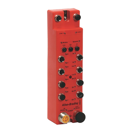
Indicator Activity Indicator Network 24V DC Network Link 2 Status Output Power Activity Indicator Indicator Safety Inputs 12…15 (1732ES-IB16) Indicator Safety Outputs 0…3 (1732ES-IB12XOB4, Safety Inputs 8…11 (1732ES-IB12XOB4, 1732ES-IB12XOBV2) 1732ES-IB12XOBV2, 1732ES-IB16) Safety Outputs 4…7 (1732ES-IB8XOB8, Safety Output 0…3 (1732ES-IB8XOB8, 1732ES-IB8XOBV4) - Page 99 Interpret the Module Status Indicators Chapter 7 Table 28 - Module Status Indicator State Status Description Recommended Action No power No power is applied to the power connector. Apply power to this connector. No power is applied to the input power connector or severe Apply input power that is within specification to the input power overvoltage.
- Page 100 Chapter 7 Interpret the Module Status Indicators Table 32 - Safety Input Status Indicator State Status Description Recommended Action Safety input off The safety input is off or the channel is configured for not used. Turn on the safety input or reconfigure the channel, if desired.
- Page 101 Appendix Get Diagnostic Status from Modules by Using Explicit Messaging Topic Page Get Status Messages from 1791ES-IB8XOBV4 Modules Get Status Messages from 1791ES-IB16 Modules Get Status Messages from 1732ES Modules I/O Data Supported by Each Module I/O Assembly and Reference Data Explicit Messages This appendix provides information about how to use CIP Generic Message instructions (sometimes called Explicit Messaging) to get diagnostic status...
-
Page 102: Get Status Messages From 1791Es-Ib8Xobv4 Modules
Appendix A Get Diagnostic Status from Modules by Using Explicit Messaging Another choice is to obtain overall status implicitly from the Module Definition dialog box by choosing Combined Status from the Input Status pull-down menu. If the Combined Status changes, use Explicit Messaging to obtain the point level status. - Page 103 Get Diagnostic Status from Modules by Using Explicit Messaging Appendix A This selection creates a two-byte input assembly, as shown for the 1791ES-IB8XOBV4 module. 2. Use the CombinedInputStatus and CombinedOutputStatus bits to detect if one or more of the I/O points on the module have a fault. •...
- Page 104 Appendix A Get Diagnostic Status from Modules by Using Explicit Messaging Figure 35…Figure 39 show the MSG instruction parameters to read Instance 852 from the 1791ES-IB8XOBV4 module. Figure 35 - Instance 852 Configuration Tab Instance 852 (354 hex) is 5 bytes in length, so the destination tag MSGdata must be at least 5 bytes in length to hold this data.
- Page 105 Get Diagnostic Status from Modules by Using Explicit Messaging Appendix A Figure 36 - Instance 852 Communication Tab 5. From the top of the Message Configuration dialog box, choose Tag. Figure 37 - Instance 852 Tag Tab Rockwell Automation Publication 1791ES-UM001G-EN-P - November 2016...
- Page 106 Appendix A Get Diagnostic Status from Modules by Using Explicit Messaging When the explicit message reads the data from the 1791ES-IB8XOBV4 module, the data appears in the MSGdata tags as shown in Figure Figure 38 - Instance 852 MSGdata Tags The first 32 bits of the instance are in MSGdata[0].0…31, and the final 8 bits are in MSGdata[1].0…7.
-
Page 107: Get Status Messages From 1791Es-Ib16 Modules
Get Diagnostic Status from Modules by Using Explicit Messaging Appendix A Get Status Messages from Follow these steps to get status messages from 1791ES-IB16 modules. 1791ES-IB16 Modules 1. In the Module Definition dialog box, from the Input Status pull-down menu, choose Combined Status. This selection creates a three-byte input assembly, as shown, for the 1791ES-IB16 module. - Page 108 Appendix A Get Diagnostic Status from Modules by Using Explicit Messaging • You can use the second rung to read the status on mode transition and once a fault is detected, continue reading until the fault is corrected. • Place these rungs in the standard task. Figure 40…Figure 44 show the MSG instruction parameters for to read Instance 869 from the 1791ES-IB16 module.
- Page 109 Get Diagnostic Status from Modules by Using Explicit Messaging Appendix A Instance 869 (365 hex) is 7 bytes in length, so the destination tag IB16MSGdata must be at least 7 bytes in length to hold this data. The size is DINT[2] or 8 bytes (see Table 35).
- Page 110 Appendix A Get Diagnostic Status from Modules by Using Explicit Messaging 5. From the top of the Message Configuration dialog box, click Tag. Figure 42 - Instance 869 Tag Tab When the explicit message reads the data from the 1791ES-IB16 module, the data appears in the MSGdata tags as shown in Figure Figure 43 - Instance 869 MSGdata Tags...
- Page 111 Get Diagnostic Status from Modules by Using Explicit Messaging Appendix A The first 32 bits of the instance are in IB16MSGdata[0].0…31, and the final 24 bits are in IB16MSGdata[1].0…23. Map these 56 bits according to Instance 869. An easy method to do this mapping is to create a user- defined tag (UDT) for Instance 869.
-
Page 112: Get Status Messages From 1732Es Modules
Appendix A Get Diagnostic Status from Modules by Using Explicit Messaging Get Status Messages from Follow these steps to get status messages from 1732ES modules. 1732ES Modules TIP The process is identical for all 1732ES modules. 1732ES-IB12XOB4 Modules 1. In the Module Definition dialog box, from the Input Status pull-down menu, choose Combined Status. - Page 113 Get Diagnostic Status from Modules by Using Explicit Messaging Appendix A • If any input or output status bits go to a value of 0 (0 = bad; 1 = good), use the CombinedInputStatus and CombinedOutputStatus bits to condition your MSG rungs as follows. Only use of the CombinedInputStatus bit is shown.
- Page 114 Appendix A Get Diagnostic Status from Modules by Using Explicit Messaging Instance 860 (35C hex) is 5 bytes in length, so the destination tag IB12XOB4MSGdata must be at least 5 bytes in length to hold this data. The size is DINT[2] or 8 bytes (see Table 36).
- Page 115 Get Diagnostic Status from Modules by Using Explicit Messaging Appendix A 5. From the top of the Message Configuration dialog box, click Tag. Figure 47 - Instance 860 Tag Tab When the explicit message reads the data from the 1732ES-IB12XOB4 modules, the data appears in the MSGdata tags as shown in Figure Figure 48 - Instance 860 MSGdata Tags...
- Page 116 Appendix A Get Diagnostic Status from Modules by Using Explicit Messaging The first 32 bits of the instance are in IB12XOB4MSGdata[0].0…31, and the final 8 bits are in IB12XOB4MSGdata[1].0…7. Map these 40 bits according to Instance 860. An easy method to do this mapping is to create a user-defined tag (UDT) for Instance 860.
-
Page 117: 1732Es-Ib12Xobv2 Modules
Get Diagnostic Status from Modules by Using Explicit Messaging Appendix A 1732ES-IB12XOBV2 Modules 1. In the Module Definition dialog box, from the Input Status pull-down menu, choose Combined Status. This selection creates a three-byte input assembly, as shown, for the 1732ES-IB12XOBV2 modules. - Page 118 Appendix A Get Diagnostic Status from Modules by Using Explicit Messaging Only use of the CombinedInputStatus bit is shown. Create similar rungs by using the CombinedOutputStatus bit instead of the CombinedInputStatus bit. • The second rung can be used to read the status on mode transition and once a fault is detected, continue reading until the fault is corrected.
- Page 119 Get Diagnostic Status from Modules by Using Explicit Messaging Appendix A Instance 860 (35C hex) is 5 bytes in length, so the destination tag IB12XOBV2MSGdata must be at least 5 bytes in length to hold this data. The size is DINT[2] or 8 bytes (see Table 37).
- Page 120 Appendix A Get Diagnostic Status from Modules by Using Explicit Messaging 5. From the top of the Message Configuration dialog box, click Tag. Figure 52 - Instance 860 Tag Tab When the explicit message reads the data from the 1732ESIB12XOBV2 modules, the data appears in the MSGdata tags as shown in Figure Figure 53 - Instance 860 MSGdata Tags...
- Page 121 Get Diagnostic Status from Modules by Using Explicit Messaging Appendix A The first 32 bits of the instance are in IB12XOBV2MSGdata[0].0…31, and the final 8 bits are in IB12XOBV2MSGdata[1].0…7. Map these 40 bits according to Instance 860. An easy method to do this mapping is to create a user-defined tag (UDT) for Instance 860.
-
Page 122: 1732Es-Ib16 Modules
Appendix A Get Diagnostic Status from Modules by Using Explicit Messaging 1732ES-IB16 Modules 1. In the Module Definition dialog box, from the Input Status pull-down menu, choose Combined Status. This selection creates a three-byte input assembly, as shown here. 2. Use the CombinedInputStatus and CombinedOutputStatus bits to detect if one or more of the I/O points on the module have a fault. - Page 123 • Place these rungs in the standard task. Figure 55…Figure 60 show the MSG instruction parameters to read Instance 821 from the 1732ES-IB16 module. See Appendix C of this manual for a layout of possible instances. Figure 55 - Instance 821 Configuration Tab...
- Page 124 IB16MSGdata must be at least 5 bytes in length to hold this data. The size is DINT[2] or 8 bytes (see Table 38). Table 38 - Layout of Instance 821 (335 hex) – 1732ES-IB16 Modules Instance Hex Connection Type Byte...
- Page 125 5. From the top of the Message Configuration dialog box, click Tag. Figure 58 - Instance 821 Tag Tab When the explicit message reads the data from the 1732ES-IB16 module, the data appears in the MSGdata tags as shown in...
- Page 126 Appendix A Get Diagnostic Status from Modules by Using Explicit Messaging The first 32 bits of the instance are in IB16MSGdata[0].0…31, and the final 8 bits are in IB16MSGdata[1].0…7. Map these 40 bits according to Instance 821. An easy method to do this mapping is to create a user- defined tag (UDT) for Instance 821.
-
Page 127: 1732Es-Ibxob8 Modules
Get Diagnostic Status from Modules by Using Explicit Messaging Appendix A 1732ES-IBXOB8 Modules 1. In the Module Definition dialog box, from the Input Status pull-down menu, choose Combined Status. This selection creates a three-byte input assembly, as shown here. 2. Use the CombinedInputStatus and CombinedOutputStatus bits to detect if one or more of the I/O points on the module have a fault. - Page 128 Appendix A Get Diagnostic Status from Modules by Using Explicit Messaging • Place these rungs in the standard task. Figure 61…Figure 65 show the MSG instruction parameters to read Instance 852 from the 1732ES-IB8XOB8 module. See Appendix C this manual for a layout of possible instances. Figure 61 - Instance 852 Configuration Tab Rockwell Automation Publication 1791ES-UM001G-EN-P - November 2016...
- Page 129 Get Diagnostic Status from Modules by Using Explicit Messaging Appendix A Instance 852 (354 hex) is 5 bytes in length, so the destination tag IB8XOB8MSGdata must be at least 5 bytes in length to hold this data. The size is DINT[2] or 8 bytes (see Table 39).
- Page 130 Appendix A Get Diagnostic Status from Modules by Using Explicit Messaging 5. From the top of the Message Configuration dialog box, click Tag to see this dialog box. Figure 63 - Instance 852 Tag Tab When the explicit message reads the data from the 1732ES-IB8XOB8 module, the data appears in the MSGdata tags as shown in Figure Figure 64 - Instance 852 MSGdata Tags...
- Page 131 Get Diagnostic Status from Modules by Using Explicit Messaging Appendix A The first 32 bits of the instance are in IB8XOB8MSGdata[0].0…31, and the final 8 bits are in IB8XOB8MSGdata[1].0…7. Map these 40 bits according to Instance 852. An easy method to do this mapping is to create a user-defined tag (UDT) for Instance 852.
-
Page 132: 1732Es-Ib8Xobv4 Modules
Appendix A Get Diagnostic Status from Modules by Using Explicit Messaging 1732ES-IB8XOBV4 Modules 1. In the Module Definition dialog box, from the Input Status pull-down menu, choose Combined Status. This selection creates a three-byte input assembly, as shown here. 2. Use the CombinedInputStatus and CombinedOutputStatus bits to detect if one or more of the I/O points on the module have a fault. - Page 133 Get Diagnostic Status from Modules by Using Explicit Messaging Appendix A • Place these rungs in the standard task. Figure 66…Figure 70 show the MSG instruction parameters to read Instance 852 from the 1732ES-IB8XOBV4 module. See Appendix C this manual for a layout of possible instances. Figure 66 - Instance 852 Configuration Tab From the top of the Message Configuration dialog box, choose the Communication tab.
- Page 134 Appendix A Get Diagnostic Status from Modules by Using Explicit Messaging Figure 67 - Instance 852 Communication Tab Instance 852 (354 hex) is 5 bytes in length, so the destination tag IB8XOBV4MSGdata must be at least 5 bytes in length to hold this data. The size is DINT[2] or 8 bytes (see Table 40).
- Page 135 Get Diagnostic Status from Modules by Using Explicit Messaging Appendix A From the top of the Message Configuration dialog box, click Tag to see this dialog box. Figure 68 - Instance 852 Tag Tab When the explicit message reads the data from the 1732ES-IB8XOBV4 module, the data appears in the MSGdata tags as shown in Figure Figure 69 - Instance 852 MSGdata Tags...
-
Page 136: I/O Data Supported By Each Module
Appendix A Get Diagnostic Status from Modules by Using Explicit Messaging The first 32 bits of the instance are in IB8XOBV4MSGdata[0].0…31, and the final 8 bits are in IB8XOBV4MSGdata[1].0…7. Map these 40 bits according to Instance 852. An easy method to do this mapping is to create a user-defined tag (UDT) for Instance 852. - Page 137 Get Diagnostic Status from Modules by Using Explicit Messaging Appendix A Table 41 - Default I/O Data Module Cat. No. Safety Connection Assembly Instance (hex) 1732ES-IB16 Safety 205 and 23 1732ES-IB8XOB8 Safety 204 and 22 1732ES-IB8XOBV4 Safety 204 and 22 The tables show the I/O data supported by each module.
- Page 138 Output Data Assembly Instance Safety – Test Combined None (1) The default Assembly Instance. Table 46 - 1732ES-IB16 Modules Input Data Input Status Assembly Instance Safety None Point Status - Muting Point Status - Muting - Test Output Combined Status - Muting...
- Page 139 Get Diagnostic Status from Modules by Using Explicit Messaging Appendix A Table 47 - 1732ES-IB8XOBV4 Modules Input Data Input Status Assembly Instance Safety None Point Status - Muting Combined Status - Muting Safety - Readback Point Status - Muting Point Status - Muting - Test Output Output Data Assembly Instance Safety...
-
Page 140: I/O Assembly And Reference Data
Appendix A Get Diagnostic Status from Modules by Using Explicit Messaging I/O Assembly and Reference This section provides information for I/O assembly and reference data. Data 1791ES Modules The bits in the tag definitions of the programming software are different than the bits shown in the following section. - Page 141 Get Diagnostic Status from Modules by Using Explicit Messaging Appendix A Table 50 - Input Data – 1791ES-IB8XOBV4 Modules (Continued) Instance Hex Connection Type Byte Bit 7 Bit 6 Bit 5 Bit 4 Bit 3 Bit 2 Bit 1 Bit 0 (decimal) 334 (820) Safety and...
- Page 142 Appendix A Get Diagnostic Status from Modules by Using Explicit Messaging Table 51 - Input Data – 1791ES-IB16 Modules Instance Hex Connection Byte Bit 7 Bit 6 Bit 5 Bit 4 Bit 3 Bit 2 Bit 1 Bit 0 (decimal) Type 205 (517) Safety and...
-
Page 143: 1732Es Modules
Get Diagnostic Status from Modules by Using Explicit Messaging Appendix A Table 52 - Output Data – 1791ES-IB8XOVB4 Modules Instance Hex Connection Type Byte Bit 7 Bit 6 Bit 5 Bit 4 Bit 3 Bit 2 Bit 1 Bit 0 (decimal) 22 (34) Safety and standard... - Page 144 Appendix A Get Diagnostic Status from Modules by Using Explicit Messaging Table 55…Table 60 for reference data related to input and output data. Table 55 - Input Data 1732ES-IB16 Modules Instance Hex Connection Type Byte Bit 7 Bit 6 Bit 5...
- Page 145 Get Diagnostic Status from Modules by Using Explicit Messaging Appendix A Table 56 - Input Data 1732ES-IB8XOBV4 and 1732ES-IB8XOB8 Modules Instance Hex Connection Type Byte Bit 7 Bit 6 Bit 5 Bit 4 Bit 3 Bit 2 Bit 1 Bit 0 (decimal) 204 (516) Safety and standard...
- Page 146 Appendix A Get Diagnostic Status from Modules by Using Explicit Messaging Table 56 - Input Data 1732ES-IB8XOBV4 and 1732ES-IB8XOB8 Modules (Continued) Instance Hex Connection Type Byte Bit 7 Bit 6 Bit 5 Bit 4 Bit 3 Bit 2 Bit 1 Bit 0 (decimal) 394 (916)
- Page 147 Get Diagnostic Status from Modules by Using Explicit Messaging Appendix A Table 57 - Input Data – 1732ES-IB12XOBV2 and 1732ES-IB12XOB4 Modules (Continued) Instance Hex Connection Type Byte Bit 7 Bit 6 Bit 5 Bit 4 Bit 3 Bit 2 Bit 1 Bit 0 (decimal) 35C (860)
- Page 148 Appendix A Get Diagnostic Status from Modules by Using Explicit Messaging Table 58 - Output Data 1732ES-IB16 Modules Instance Hex Connection Type Byte Bit 7 Bit 6 Bit 5 Bit 4 Bit 3 Bit 2 Bit 1 Bit 0 (decimal)
-
Page 149: Explicit Messages
Get Diagnostic Status from Modules by Using Explicit Messaging Appendix A Explicit Messages Explicit Messaging can also be used to read individual channel status for safety inputs, safety outputs, test outputs, and power status. You can also configure communication error settings for test outputs. Table 61 - Reading the Cause of the Safety Input Error Explicit Service... - Page 150 Appendix A Get Diagnostic Status from Modules by Using Explicit Messaging Table 64 - Setting Hold/Clear for Communications Errors (test output) Explicit Message Service Function Command (hex) Response (hex) Service Class Instance ID Attribute ID Data Code Size Setting for output Get attribute Reads whether hold or clear 01…08...
-
Page 151: Calculated Values
Appendix Safety Data This appendix lists calculated values for probability of failure on demand (PFD), probability of failure per hour (PFH), and mean time to failure (MTTF). PFD and PFH calculations comply with IEC 61508, edition 2, 2010. Calculated Values Calculated values of probability of failure on demand and probability of failure per hour appear in Table... - Page 152 Appendix B Safety Data Figure 24 - PFD vs. Proof Test Interval 1791ES-IB8XOBV4 Single Channel Inputs Figure 25 - PFD vs. Proof Test Interval 1791ES-IB8XOBV4 Dual Channel Inputs Figure 26 - PFD vs. Proof Test Interval 1791ES-IB8XOBV4 Dual Channel Outputs Figure 27 - PFD vs.
- Page 153 Figure 28 - PFD vs. Proof Test Interval 1791ES-IB16 Dual Channel Inputs Figure 29 - PFD vs. Proof Test Interval 1732ES-IB12XOBV2, 1732ES-IB12XOB4, 1732ES- IB8XOBV4, 1732ES-IB8XOB8, 1732ES-IB16 - Single Channel Inputs Figure 30 - PFD vs. Proof Test Interval 1732ES-IB12XOBV2, 1732ES-IB12XOB4, 1732ES- IB8XOBV4, 1732ES-IB8XOB8, 1732ES-IB16 - Dual Channel Inputs Figure 31 - PFD vs.
- Page 154 Appendix B Safety Data Figure 32 - PFD vs. Proof Test Interval 1732ES-IB12XOB4, 1732ES-IB8XOB8 - Single Channel Outputs Figure 33 - PFD vs. Proof Test Interval 1732ES-IB12XOB4, 1732ES-IB8XOB8 - Dual Channel Output (1) Single channel output mode is only valid for applications with Process Safety Times ≥ 600msec OR with Demand Rates ≤ 1 Demand per Minute.
- Page 155 Safety Data Appendix B Table 65 - Calculated Values for Probability of Failure on Demand (PFD), Probability of Failure per Hour (PFH), and Mean Time To Failure (MTTF) Cat. No. Proof Test Interval Spurious MTTF Spurious (Mission Time Trip Rate (years) (1/hour) (STR)
- Page 156 Appendix B Safety Data Cat. No. Proof Test Interval Spurious MTTF Spurious (Mission Time Trip Rate (years) (1/hour) (STR) Year Hour 1732ES-IB12XOB4 8760 2.32E-06 5.38E-10 6.670E-06 17.12 Single Channel Inputs 17520 4.63E-06 43800 1.16E-05 87600 2.33E-05 175200 4.69E-05 1732ES-IB12XOB4 8760 5.51E-07 1.35E-10 Dual Channel Inputs 17520...
- Page 157 87600 2.95E-04 175200 5.91E-04 1732ES-IB8XOB8 8760 5.62E-07 1.38E-10 Dual Channel Outputs 17520 1.13E-06 43800 2.84E-06 87600 5.75E-06 175200 1.18E-05 1732ES-IB16 8760 2.32E-06 5.38E-10 6.526E-06 17.49 Single Channel Inputs 17520 4.63E-06 43800 1.16E-05 87600 2.33E-05 175200 4.69E-05 1732ES-IB16 8760 5.51E-07 1.35E-10...
- Page 158 2.0350E-10 Single Channel Outputs 2.8910E-07 2.8910E-07 6.4630E-09 Dual Channel Outputs 3.5140E-07 3.5140E-07 2.0660E-10 1732ES-IB16 Single Channel Inputs 2.7190E-07 2.7190E-07 5.8410E-10 Dual Channel Inputs 3.0730E-07 3.0730E-07 2.0350E-10 (1) These failure rates assume that a module's inputs or outputs are represented by a single block in a reliability block diagram (the single channel rates should be applied to the reliability block if the module is configured in Single Channel mode, the dual channel rates should be applied to the reliability block if the module is configured in Dual Channel mode).
-
Page 159: Parameter Groups
Appendix Configuration Reference Information The modules have these parameter groups: general parameters, safety input, test output, safety output. Parameter Groups Table 67…Table 70 for the settings in each parameter group. All parameters are set by using the Studio 5000 Logix Designer® application. Table 67 - General Parameters Parameter Name Value... - Page 160 An indicator is connected and turned ON to detect broken lines in an external indicator. 1791ES-IB8XOBV4, 1732ES-IB8XOBV4, 1732ES-IB8XOB8 modules = T3 and T7 1791ES-IB16, 1732ES-IB16 modules = T3, T7, T11, and T15 1732ES-IB12XOBV2, 1732ES-IB12XOB4 modules = T3, T7, and T11...
-
Page 161: Technical Specifications
Appendix Specifications Topic Page Technical Specifications Environmental Specifications Certifications Europe EC Directives Technical Specifications This section provides technical specifications for the modules. 1791ES Modules For 1791ES modules, see Table 71 Table Table 71 - 1791ES-IB16 and 1791ES-IB8XOBV4 Modules – Technical Specifications Attribute Value Safety input... - Page 162 Appendix D Specifications Table 71 - 1791ES-IB16 and 1791ES-IB8XOBV4 Modules – Technical Specifications (Continued) Attribute Value Output types Current sourcing/current sinking – bipolar pair Output current rating 2 A max per point 8 A total module at 40 °C (104 °F) (see temperature versus current derating) 6 A total module at 60 °C (140 °F) Voltage and current ratings IN PWR (No Load): 19.2-28.8 Vdc, 190 mA @ 24 Vdc typ.
-
Page 163: 1732Es Modules
0.7 A max per point at 40 °C (104 °F) (all 1732ES modules except 1732ES-IB16) 0.3 A max per point at 55 °C (131 °F) Product temperature versus pulse test output current derating (All 1732ES modules except 1732ES-IB16) on page 165. - Page 164 Appendix D Specifications Table 73 - 1732ES-IB16, 1732ES-IB8XOB8, 1732ES-IB8XOBV4, 1732ES-IB12XOB4, and 1732ES-IB12XOBV2 Modules – Technical Specifications Attribute Value Output leakage current, max 0.1 mA Short circuit protection Current, max 25 mA – current, max (to avoid fault when used as a muted lamp output) Current, min 5 mA –...
- Page 165 Specifications Appendix D Table 74 - 1732ES-IB16, 1732ES-IB8XOB8, 1732ES-IB8XOBV4, 1732ES-IB12XOB4, and 1732ES-IB12XOBV2 Modules – General (Continued) Attribute Value Isolation voltage 50V (continuous), Basic Type, Input Power and I/O to Ethernet, Input Power and I/O to Output Power and IO, and...
-
Page 166: Environmental Specifications
Appendix D Specifications Environmental Specifications This section provides environmental specifications for the modules. • For 1791ES modules, see Table 75 on page 166. • For 1732ES modules, see Table 76 on page 167. Table 75 - 1791ES-IB16 and 1791ES-IB8XOBV4 Modules – Environmental Specifications Attribute Value Temperature, operating... - Page 167 Specifications Appendix D Table 76 - 1732ES-IB16, 1732ES-IB8XOB8, 1732ES-IB8XOBV4, 1732ES-IB12XOB4, and 1732ES-IB12XOBV2 Modules – Environmental Specifications Attribute Value Temperature, operating -20…+55 °C (-4…+131 °F) IEC 60068-2-1 (Test Ad, Operating Cold), (All 1732ES modules except 1732ES-IB16 modules) IEC 60068-2-2 (Test Bd, Operating Dry Heat),...
-
Page 168: Certifications
This section provides certification information for the 1791ES and 1732ES modules. Table 77 - 1791ES and 1732ES Modules – Certifications Certification 1732ES-IB16, 1732ES-IB8XOB8, 1732ES-IB8XOBV4, 1732ES-IB12XOBV2, 1732ES-IB12XOB4, 1791ES-IB16, 1791ES-IB8XOBV4 European Union 2004/108/EC EMC Directive, compliant with these norms: EN 61326-1; Meas./Control/Lab, Industrial Requirements EN 61000-6-2;... -
Page 169: North America
Specifications Appendix D North America In North America, the TÜV-Rheinland type approval includes Guard I/O compliance to the relevant standards and related information including the following: • U.S. standards - ANSI RIA15.06, ANSI B11.19, NFPA 79 • The modules are UL-certified functionally safe and carry the NRGF label, when product is marked (only 1791ES modules). - Page 170 Appendix D Specifications • Use reinforced insulation or double insulation for the DC power supplies used for the communication power supply, internal- circuit power supply, and the I/O power supplies. • EtherNet/IP products that comply with EC directives also conform to the Common Emission Standard (EN 50081-2).
-
Page 171: Index
Numerics prevention 45 Electronic Data Sheet 9 1732ES-IB12XOB4 33 EMC Directives 169 1732ES-IB12XOBV2 33 emergency stop switch 26 1732ES-IB16 33 EN 50081-2 170 1732ES-IB8XOB8 33 EtherNet/IP cables 1732ES-IB8XOBV4 33 recommended 59 1791ES-IB16 33 EtherNet/IP safety network 34 1791ES-IB8XOBV4 33... - Page 172 Index probability of failure on demand 9 probability of failure per hour 9 Japan 169 programming requirements 34 limit switches 26 redundant channel safety devices 17 replacement stock 44 reset ownership 87 RPI 86 maximum current 56 RSLogix 5000 software mean time between failure 9 version 34 model types 32...
- Page 173 Index wiring by application dual-load bipolar outputs 73 dual-load sourcing outputs – only 1732ES- IB12XOB4 module 74 emergency stop switch dual-channel inputs with manual reset 67 Guard I/O module with limit switch dual- channel inputs and a manual reset 72 limit switch dual-channel inputs and a manual reset 71 mode select switch 69...
- Page 174 Index Notes: Rockwell Automation Publication 1791ES-UM001G-EN-P - November 2016...
- Page 176 Rockwell Automation maintains current product environmental information on its website at http://www.rockwellautomation.com/rockwellautomation/about-us/sustainability-ethics/product-environmental-compliance.page. Allen-Bradley, ArmorBlock, CompactBlock, Guard I/O, GuardLogix, GuardMaster, POINT Guard I/O, Rockwell Automation, Rockwell Software, RSLinx, RSLogix, RSLogix 5000, RSNetWorx, RSView, Stratix, Studio 5000, and Studio 5000 Logix Designer are trademarks of Rockwell Automation, Inc.
Need help?
Do you have a question about the 1732ES-IB16 and is the answer not in the manual?
Questions and answers