Vega VEGAFLEX 62 Operating Instructions Manual
Hide thumbs
Also See for VEGAFLEX 62:
- Product information (15 pages) ,
- Operating instructions manual (64 pages) ,
- Operating instructions manual (56 pages)
Table of Contents
Advertisement
Quick Links
Advertisement
Table of Contents

Related Manuals for Vega VEGAFLEX 62


Summary of Contents for Vega VEGAFLEX 62
-
Page 1: Operating Instructions
Operating Instructions VEGAFLEX 62 Profibus PA Guided Microwave... -
Page 2: Table Of Contents
Setup procedure ..... . . 31 Menu schematic ..... . . 38 VEGAFLEX 62 • Profibus PA... - Page 3 "Product description". Instructions manuals for accessories and replacement parts Tip: To ensure reliable setup and operation of your VEGAFLEX 62, we offer accessories and replacement parts. The associated documents are: 27720 - VEGADIS 61 30207 - Electronics module VEGAFLEX series 60...
-
Page 4: About This Document
This symbol indicates special instructions for Ex applications. List The dot set in front indicates a list with no implied sequence. à Action This arrow indicates a single action. Sequence Numbers set in front indicate successive steps in a procedure. VEGAFLEX 62 • Profibus PA... -
Page 5: For Your Safety
During work on and with the device the required personal protection equipment must always be worn. 2.2 Appropriate use VEGAFLEX 62 is a sensor for continuous level measurement. You can find detailed information on the application range in chapter "Product description". -
Page 6: Safety Approval Markings And Safety Tips
NE 53 is fulfilled. This applies also to the corresponding indicating and adjustment components. VEGA instruments are generally upward and downward compatible. Sensor software for DTM VEGAFLEX 62 HART, PA or FF DTM VEGAFLEX 62 for adjustment software PACTware Indicating and adjustment module for sensor software The parameter adjustment of the basic sensor functions is independent of the software version. -
Page 7: Safety Instructions For Ex Areas
PACTware on the type label of the electronics via the indicating and adjustment module You can view all software histories on our website www.vega. com. Make use of this advantage and get registered for update information via e-mail. 2.8 Safety instructions for Ex areas Please note the Ex-specific safety information for installation... -
Page 8: Product Description
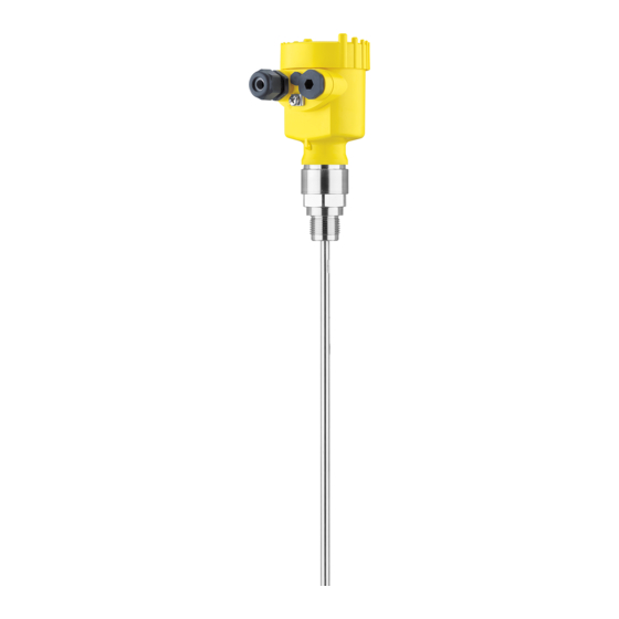
Process fitting with probe Housing with electronics Housing cover, optionally available with indicating and adjustment module Fig. 1: VEGAFLEX 62 - cable version with plastic housing Housing cover with integrated indicating and adjustment module (optional) Housing with electronics Process fitting... -
Page 9: Principle Of Operation
In addition to the type label outside, you can also find the serial number on the inside of the instrument. 3.2 Principle of operation VEGAFLEX 62 is a level sensor with cable or rod probe for Application range continuous level measurement. -
Page 10: Operation
3 Product description 3.3 Operation VEGAFLEX 62 can be adjusted with different adjustment media: with indicating and adjustment module with the suitable VEGA DTM in conjunction with an adjustment software according to the FDT/DTM standard, e.g. PACTware and PC with the adjustment program PDM... - Page 11 3 Product description Relative humidity 20 … 85 % VEGAFLEX 62 • Profibus PA...
-
Page 12: Mounting
Fig. 2: Measures against moisture penetration The reference plane for the measuring range of the sensors is Measuring range the sealing surface of the thread or flange. VEGAFLEX 62 • Profibus PA... -
Page 13: Mounting Instructions
"Technical data" or on the type label of the sensor. 4.2 Mounting instructions Mount VEGAFLEX 62 in such a way that the distance to vessel Mounting position installations or to the vessel wall is at least 300 mm (12 in). - Page 14 (lower dead band) is stated in chapter "Technical data". Fig. 3: Vessel with conical bottom In case of difficult installation conditions, the probe can be also Rod extensions mounted laterally. For this purpose, adapt the rod with rod extensions or bow-shaped segments. VEGAFLEX 62 • Profibus PA...
- Page 15 Rod length 100 … 2000 mm (3.937 … 78.74 in) Thread length 60 mm (2.362 in) Make sure that the rod of the probe is at least 300 mm (11.811 in) away from the vessel wall VEGAFLEX 62 • Profibus PA...
- Page 16 When installing rod or cable probes without metal vessel wall, e.g. in plastic vessels, the measured value can be influenced by strong electromagnetic fields (emitted interference accord- ing to EN 61326: class A). In this case, use a probe in coax version. VEGAFLEX 62 • Profibus PA...
- Page 17 Flange Metal sheet Concrete vessel When installed in thick concrete ceilings, VEGAFLEX 62 should be mounted front flush to the lower edge. In concrete silos, the distance to the wall should be at least 500 mm (20 in). ø >160 mm ø...
- Page 18 ≤ 100 Fig. 8: Mounting socket When welding the socket, make sure that the socket is flush to the vessel wall. Fig. 9: Socket must be installed flush Unfavourable installation Socket flush - optimum installation VEGAFLEX 62 • Profibus PA...
- Page 19 Measuring probes can be mounted in bypass tubes up to DN 200. If VEGAFLEX 62 is used in standpipes or bypass tubes, contact with the tube wall should be avoided. We offer spacers as accessories for fastening the probe in the middle of the tube.
- Page 20 Make sure that the probe is not subjected to strong lateral Inflowing medium forces. Mount VEGAFLEX 62 at a position in the vessel where no disturbances, e.g. from filling openings, agitators, etc., can occur. Fig. 11: Lateral load...
-
Page 21: Connecting To Power Supply
Connect only in the complete absence of line voltage If overvoltage surges are expected, overvoltage arresters should be installed according to Profibus specifications Tip: We recommend VEGA overvoltage arrester B63-32. In hazardous areas you should take note of the appropriate Take note of safety instruc- regulations, conformity and type approval certificates of the... -
Page 22: Connection Steps - Instrument Housing
5.2 Connection steps - Instrument housing Proceed as follows: 1 Unscrew the housing cover 2 If an indicating and adjustment module is installed, remove it by turning it slightly to the left. 3 Loosen compression nut of the cable entry VEGAFLEX 62 • Profibus PA... -
Page 23: Wiring Plan, Single Chamber Housing
12 Screw the housing cover on The electrical connection is finished. 5.3 Wiring plan, single chamber housing The following illustrations apply to the non-Ex as well as to the Ex-ia version. VEGAFLEX 62 • Profibus PA... - Page 24 Fig. 14: Electronics and connection compartment, single chamber housing Plug connector for VEGACONNECT (I²C interface) Spring-loaded terminals for connection of the external indication VEGADIS Ground terminal for connection of the cable screen Spring-loaded terminals for voltage supply VEGAFLEX 62 • Profibus PA...
-
Page 25: Wiring Plan, Double Chamber Housing
Ex-ia version. Housing overview Fig. 16: Double chamber housing Housing cover, connection compartment Blind stopper or plug M12 x 1 for VEGADIS 61 (optional) Housing cover, electronics compartment Filter element for air pressure compensation Cable gland VEGAFLEX 62 • Profibus PA... - Page 26 Terminals for VEGADIS 61 Connection compart- ment I ² C Fig. 18: Connection compartment, double chamber housing Plug connector for VEGACONNECT (I²C interface) Ground terminal for connection of the cable screen Spring-loaded terminals for voltage supply VEGAFLEX 62 • Profibus PA...
-
Page 27: Wiring Plan - Version Ip 66/Ip 68, 1 Bar
5.5 Wiring plan - version IP 66/IP 68, 1 bar Wire assignment, con- nection cable Fig. 20: Wire assignment, connection cable brown (+) and blue (-) to power supply or to the processing system Shielding VEGAFLEX 62 • Profibus PA... -
Page 28: Set Up With The Indicating And Adjustment Module
4 Screw housing cover with inspection window tightly back Removal is carried out in reverse order. The indicating and adjustment module is powered by the sensor, an additional connection is not necessary. VEGAFLEX 62 • Profibus PA... - Page 29 Fig. 21: Installation of the indicating and adjustment module Note: If you intend to retrofit the instrument with an indicating and adjustment module for continuous measured value indication, a higher cover with an inspection glass is required. VEGAFLEX 62 • Profibus PA...
-
Page 30: Adjustment System
The functions of the individual keys are shown in the above illustration. Approx. 10 minutes after the last pressing of a key, an automatic reset to measured value indication is triggered. Any values not confirmed with [OK] will not be saved. VEGAFLEX 62 • Profibus PA... -
Page 31: Setup Procedure
6 Set up with the indicating and adjustment module PLICSCOM 6.4 Setup procedure After VEGAFLEX 62 is connected to voltage supply or after Switch on phase voltage recurrence, the instrument carries out a self-check for approx. 30 seconds. The following steps are carried out: Internal check of the electronics Indication of the instrument type, the firmware as well as... - Page 32 1 Prepare the % value for editing with [OK] and set the cursor to the requested position with [->]. Set the requested percentage value with [+] and save with [OK]. The cursor jumps now to the distance value. VEGAFLEX 62 • Profibus PA...
- Page 33 In general, a period of a few seconds is sufficient to smooth the measured value display. Damping Enter the requested parameter via the appropriate keys, save your settings and jump to the next menu item with the [->] key. VEGAFLEX 62 • Profibus PA...
- Page 34 [->] key. Caution: Note the following, if VEGAFLEX 62 is used as part of an overfill protection system according to WHG: If a linearisation curve is selected, the measuring signal is no longer compulsorily linear proportional to the level.
- Page 35 "Indicating and adjustment module". The following data are read out or written with this function: Measured value presentation Adjustment Medium Vessel form Damping Linearisation curve Sensor-TAG Displayed value Unit of measurement Language Sensitivity PA scaling unit VEGAFLEX 62 • Profibus PA...
- Page 36 100.0 lin % = 100 % The values of the following menu items are not reset to the reset values (see chart) with "Reset": Function Reset value Sensor address no reset Language no reset Sensor-specific basic adjustment. VEGAFLEX 62 • Profibus PA...
- Page 37 You will find a detailed description of these menu items in the operating instructions manual "Indicating and adjustment module". Special parameters are parameters which are set customer-specifically on the service level with the adjustment software PACTware. VEGAFLEX 62 • Profibus PA...
-
Page 38: Menu Schematic
Primary Value Switched off ▼ Diagnostics Basic adjustment Display ▶ Diagnostics Service Info Pointer Sensor status Curve selection Echo curve Distance min.: 0.580 m(d) Echo curve Presentation of the echo Dist. max.: 16.785 m(d) curve VEGAFLEX 62 • Profibus PA... - Page 39 Enable? select? Info Basic adjustment Display Diagnostics Service ▶ Info Sensor type Date of manufacture Last change using PC Sensor characteristics 4. July 2007 Software version Display now? 3.50 4. July 2007 Serial number 12345678 VEGAFLEX 62 • Profibus PA...
-
Page 40: Setup With Pactware And Other Adjustment Programs
A detailed description is available in the online help of PACTware and the VEGA DTMs. Note: Keep in mind that for setup of VEGAFLEX 62, DTM-Collection in the actual version must be used. VEGAFLEX 62 • Profibus PA... -
Page 41: Parameter Adjustment With Pdm
All currently available VEGA DTMs are provided in the DTM Collection on CD and can be obtained from the responsible VEGA agency for a token fee. This CD includes also the up-to- date PACTware version. The basic version of this DTM Collection incl. -
Page 42: Maintenance And Fault Rectification
24 hour service hotline However, should these measures not be successful, call the VEGA service hotline in urgent cases under the phone no. +49 1805 858550. The hotline is available to you 7 days a week round-the-clock. - Page 43 Fault messages via the indicating/adjustment no measured value available module à sensor in boot phase à Sensor does not find an echo, e.g. due to faulty installation or wrong parameter adjustment à Wrong sensor length entered VEGAFLEX 62 • Profibus PA...
-
Page 44: Exchange Or Shorten Cable/Rod
4 Screw in a new measuring part manually 5 Exert counterforce with the second fork spanner and tighten the meas. part on the flat surfaces with a torque of 15 Nm (11 lbf ft). VEGAFLEX 62 • Profibus PA... - Page 45 6 Cable: Fasten the cable with three pins, torque 20 Nm (14.75 lbf in) 7 Enter new probe length and then carry out a fresh adjustment (see "Setup procedure, Carrying out min. adjustment - Carrying out max. adjustment"). VEGAFLEX 62 • Profibus PA...
-
Page 46: Exchanging The Electronics Module
Internet (see operating instructions manual "Oscillator"). In both cases, the serial number of VEGAFLEX 62 is required. The serial numbers are stated on the type label of VEGAFLEX 62, on the inner wall of the housing or on the delivery note. -
Page 47: Instrument Repair
If a repair is necessary, please proceed as follows: You can download a return form (23 KB) from our Internet homepage www.vega.com under: "Downloads - Forms and certificates - Repair form". By doing this you help us carry out the repair quickly and without having to call back for needed information. -
Page 48: Dismounting
Correct disposal avoids negative effects to persons and environment and ensures recycling of useful raw materials. Materials: see chapter "Technical data" If you have no possibility to dispose of the old instrument professionally, please contact us concerning return and disposal. VEGAFLEX 62 • Profibus PA... -
Page 49: Supplement
Process fittings - Pipe thread, cylindrical (ISO 228 T1) G¾ A, G1 A, G1½ A ¾ NPT, 1 NPT, 1½ NPT - American pipe thread, tapered DIN from DN 25, ANSI from 1" - Flanges VEGAFLEX 62 • Profibus PA... - Page 50 Dead zone with rod: ø 16 mm (0.63 in) 80 mm (3.15 in) - top 0 mm - bottom Dead zone with cable: ø 6 mm (0.236 in) 150 mm (5.906 in) - top 250 mm (9.843 in) - bottom VEGAFLEX 62 • Profibus PA...
- Page 51 10 Supplement Fig. 26: Measuring ranges of VEGAFLEX 62 Reference plane Probe length Measuring range Upper dead band Lower dead zone (only with cable versions) Output variable Output signal digital output signal, format according to IEEE-754 126 (default setting) Sensor address 10 mA, ±0.5 mA...
-
Page 52: Air Pressure
") 3 mm ") -3 mm ") -10 mm ") 0,08 m 0,5 m 0,1 m (0.26 ft) (1.6 ft) (0.33 ft) Fig. 27: Deviation VEGAFLEX 62 in rod version Incl. non-linearity, hysteresis and non-repeatability. VEGAFLEX 62 • Profibus PA... - Page 53 0,15 m 0,5 m 0,35 m 0,25 m (0.5 ft) (1.6 ft) (1.15 ft) (0.82 ft) Fig. 28: Deviation VEGAFLEX 62 in cable version, length L < 15.000 mm 10 mm ") 3 mm ") -3 mm ") -10 mm ")
- Page 54 -40 °C 0 °C 50 °C 100 °C 150 °C (-40 °F) (32 °F) (122 °F) (212 °F) (302 °F) Fig. 30: Ambient temperature - Process temperature Ambient temperature Process temperature (depending on the seal material) VEGAFLEX 62 • Profibus PA...
- Page 55 1 x IP 68 cable gland M20 x 1.5; 1 x blind - Double chamber housing stopper M20 x 1.5; 1 x blind stopper M16 x 1.5 Depending on the version M12 x 1, according to DIN 43650, Harting, Am- phenol-Tuchel, 7/8" FF. VEGAFLEX 62 • Profibus PA...
- Page 56 12 … 24 V DC - EEx-ia instrument Power supply by/max. number of sensors max. 32 (max. 10 with Ex) - DP/PA segment coupler - VEGALOG 571 EP card max. 15 (max. 10 with Ex) VEGAFLEX 62 • Profibus PA...
- Page 57 CI.I-III, Div 1 (IS); CSA CI.I-III, Div 1 (IS)+Cl.I- III, Div 1 Gr.C-G(XP) - Others A suitable cable is the prerequisite for maintaining the protection class. Deviating data in Ex applications: see separate safety instructions. VEGAFLEX 62 • Profibus PA...
-
Page 58: Profibus Pa - Data Format And Status Byte
Description according to Pro- Possible cause code fibus standard 0x00 bad - non-specific Flash-Update active 0x04 bad - configuration error Adjustment error Configuration error with PV-Scale (PV-Span too small) Unit irregularity Error in the linearization table VEGAFLEX 62 • Profibus PA... - Page 59 0x51 uncertain - sensor; conversion Sensor value < lower limit not accurate - low limited 0x52 uncertain - sensor; conversion Sensor value > upper limit not accurate - high limited VEGAFLEX 62 • Profibus PA...
-
Page 60: Dimensions
Fig. 33: Housing versions in protection IP 66/IP 67 and IP 66/IP 68, 0.2 bar (with integrated indicating and adjustment module the housing is 9 mm/0.35 in higher) Plastic housing Stainless steel housing, electropolished Stainless steel housing - precision casting Aluminium double chamber housing Aluminium housing VEGAFLEX 62 • Profibus PA... - Page 61 Fig. 34: Housing versions in protection IP 66/IP 68, 1 bar (with integrated indicating and adjustment module the housing is 9 mm/0.35 in higher) Stainless steel housing - precision casting Aluminium double chamber housing Stainless steel housing, electropolished Aluminium housing VEGAFLEX 62 • Profibus PA...
- Page 62 G1½, 1½ NPT ø 6 mm (0.24") ø 30 mm (1.18") ø 16 mm (0.63") 12 mm ø 30 mm (0.47") (1.18") ø 54 mm (2.13") Fig. 35: VEGAFLEX 62 Sensor length, see chapter "Technical data" VEGAFLEX 62 • Profibus PA...
-
Page 63: Industrial Property Rights
10 Supplement 10.4 Industrial property rights VEGA product lines are global protected by industrial property rights. Further information see http://www.vega.com. Only in U.S.A.: Further information see patent label at the sensor housing. VEGA Produktfamilien sind weltweit geschützt durch gewerbliche Schutzrechte. - Page 64 All statements concerning scope of delivery, application, practical use and operating conditions of the sensors and processing systems correspond to the information avail- able at the time of printing. © VEGA Grieshaber KG, Schiltach/Germany 2008 31839-EN-080716 Subject to change without prior notice...
Need help?
Do you have a question about the VEGAFLEX 62 and is the answer not in the manual?
Questions and answers