Table of Contents
Advertisement
Quick Links
Advertisement
Table of Contents
Troubleshooting

Related Manuals for Beckman Coulter UniCel DxC 600


Summary of Contents for Beckman Coulter UniCel DxC 600
-
Page 1: Instructions For Use
UniCel DxC Synchron Clinical Systems For In Vitro Diagnostic Use This manual is intended for ® UniCel DxC 600 ® UniCel DxC 800 ® UniCel DxC 600i A13914AF April 2010 Beckman Coulter, Inc. 250 S. Kraemer Blvd. Brea, CA 92821... - Page 2 Beckman Coulter Ireland, Inc. Mervue Business Park, Mervue Galway, Ireland 353 91 774068 Beckman Coulter do Brasil Com e Imp de Prod de Lab Ltda Estr dos Romeiros, 220 - Galpao G3 - Km 38.5 06501-001 - Sao Paulo - SP - Brasil CNPJ: 42.160.812/0001-44...
-
Page 3: Chapter 9: Maintenance,
• Added Sample Integrity CHAPTER 3, System Setup Options: • Added footnotes to Table 3.3, UniCel DxC 600 Predefined Special Calculation Formulas Table 3.4, UniCel DxC 800 Predefined Special Calculation Formulas CHAPTER 9, Maintenance: • Added Twice Weekly bullet to Maintenance Schedule •... - Page 4 Revision History A13914AF...
- Page 5 Safety Notice Summary of Hazards Introduction This section summarizes the hazards associated with the DxC System. Individual hazards associated with a specific procedure in this manual are included in within the procedures Warnings Cautions for that task. Please read this section and the following Summary of Precautions before operating the system.
- Page 6 10% bleach solution, or use your laboratory decontamination solution. Then follow your laboratory procedure for disposal of hazardous materials. If the UniCel DxC system needs to be decontaminated, call your Beckman Coulter Service Representative for assistance. ISE Module Hazards Pinch hazard.
- Page 7 If the equipment is used in a manner not specified by Beckman Coulter, Inc., the protection provided by the equipment may be impaired.
- Page 8 Safety Notice Summary of Precautions Summary of Precautions Introduction This section summarizes the precautions that should be taken when operating the DxC System. Individual precautions associated with a specific procedure in this manual are included in Caution boxes within the procedures for that task. Please read this section and the preceding Summary of Hazards before operating the system.
- Page 9 Synchron Microtubes (PN 756776) on Array systems may result in short sampling, incorrect results, and/or sample probe damage. • The use of non-Beckman Coulter, third party Microtubes, which have not been designed and tested on Synchron Systems may result in system damage and/or short sampling.
- Page 10 Safety Notice Summary of Precautions CTS (Closed Tube Sampling) Cap Piercer Precautions Use only validated sample containers with the CTS to avoid level sense errors. CTS Tracking Loss Precautions For systems with 1-Blade CTS, if there is an unusual loss of network communication, follow the instructions in the message that appears.
- Page 11 CHAPTER 5, Troubleshooting, of the UniCel DxC Synchron Clinical Systems Reference Manual or CHAPTER 12, Troubleshooting Calibration and Result Errors of this manual. If the motion error continues, contact your Beckman Coulter representative. Narrow Margin Bar Code Precautions The sample bar code reader on the DxC System can read narrow-margin bar codes. Because of the sensitivity needed to read narrow-margin bar codes, the labels must be high quality.
- Page 12 DI water. When running in the CTS mode, if tubes off-loaded from the UniCel DxC Systems have water or droplets of water on the caps, disable the CTS and the contact the Beckman Coulter Support Center. NOTE Oil on a cap is normal.
-
Page 13: Analysis,
ERASING it before copying data. Be sure the diskette does not contain critical data that is not available from another source. System Configuration Change Precautions Changes to the System Configuration Data should only be done at the request or at the direction of Beckman Coulter, Inc. Entry of incorrect information leads to system errors. xiii A13914AF... - Page 14 Safety Notice Summary of Precautions System Restore Precautions System Parameter and Alignment data can be restored from the backup diskettes onto the system; however, performing the Restore function deletes some or all files (depending on the areas restored) from the hard drive. Urine Sample Precautions After analysis of ten consecutive urine electrolytes, run one replicate of electrolytes on Synchron Calibrator Level 2 in the serum mode.
- Page 15 Safety Notice Hardware Symbols and Labels Hardware Symbols and Labels Introduction This section briefly describes symbols and labels used on the DxC Systems. They are affixed to the appropriate components of the system. Instrument Power Switch, ON This symbol located on the main power switch indicates that the analyzer power is ON when this portion of the switch is in the down position.
-
Page 16: Keyboard Connection
Safety Notice Hardware Symbols and Labels Monitor Switch, ON/OFF This symbol is located on the monitor power switch. A green light to the left of this symbol indicates the power is ON. CPU Power OFF Switch This symbol is located on the face of the Computer (CPU) unit and indicates the OFF state when pressed. - Page 17 Safety Notice Hardware Symbols and Labels Can Hold This Object Here This black symbol, located on the bottom of each sample and reagent probe assembly, indicates that this area may be handled to rotate the probe. Do Not Hold This Object Here This red symbol, located on the top of each sample and reagent probe assembly, indicates that this area may not be handled.
- Page 18 Safety Notice Hardware Symbols and Labels CAUTION This symbol indicates a caution message and is followed by an explanation or other symbols that define the caution (see examples below). CAUTION Operate with All Covers in Place This symbol is located on top of the work surface cover and the cover of an optional Cap Piercer. It indicates a caution to operate only with all covers in place to reduce risk of personal injury or biohazard.
- Page 19 Safety Notice Hardware Symbols and Labels Class II Laser Caution Warning A label reading, "CAUTION. LASER LIGHT - DO NOT STARE INTO BEAM. 670 nm - 1mW CLASS II LASER PRODUCT." is placed near any opening through which a bar code reading beam is emitted. Do not stare into laser light beam.
- Page 20 Safety Notice Hardware Symbols and Labels ISE Cover Caution A label reading, "THE ISE COVER SHOULD REMAIN IN PLACE DURING SYSTEM OPERATION." is placed on top of the ISE module frame under the ISE cover to indicate that the ISE cover should remain in place during system operation.
- Page 21 This label is found on the back, bottom edge of the system. It provides information about the laser. PRODUCT COMPLIES WITH 21 CFR CHAPTER I, SUBCHAPTER J MANUFACTURED DECEMBER 2004 LABEL P/N 448229 AB BECKMAN COULTER, INC MADE IN U.S.A. MARCA REG A011540L.EPS A13914AF...
- Page 22 Safety Notice Hardware Symbols and Labels Ethernet/Serial Port Label This label is found on the right side of the system and identifies connections for the Ethernet and serial ports. SERIAL PORT ETHERNET A012942L.EPS Fluid Interface Label This label is found on the center, back, bottom edge of the system. It identifies inlet and outlet ports on the system.
- Page 23 For Beckman Coulter products that have this label please contact your dealer or local Beckman Coulter office for details on the take back program that will facilitate the proper collection, treatment, recovery, recycling and safe disposal of device.
- Page 24 Safety Notice Hardware Symbols and Labels Restriction of Hazardous Substances (RoHS) Labels These labels and materials declaration table (the Table of Hazardous Susbtance's Name and Concentration) are to meet People's Republic of China Electronic Industry Standard SJ/T11364-2006 "Marking for Control of Pollution Caused by Electronic Information Products" requirements RoHS Caution Label This logo indicates that this electronic information product contains certain toxic or hazardous elements, and can be used safely during its environmental protection use period.
- Page 25 Documentation Symbols Documentation Symbols Read all product manuals and consult with Beckman Coulter-trained personnel before attempting to operate instrument. Do not attempt to perform any procedure before carefully reading all instructions. Always follow product labeling and manufacturer’s recommendations. If in doubt as to how to proceed in any situation, contact your Beckman Coulter representative.
- Page 26 Safety Notice Documentation Symbols xxvi A13914AF...
-
Page 27: Table Of Contents
Contents Revision History, iii Safety Notice, v Introduction, xxxiii System Description, 1-1 CHAPTER 1: System Description, 1-1 Operational Conditions, 1-1 System Components, 1-5 Sample Handling System, 1-6 Modular Chemistry (MC) System, 1-12 Cartridge Chemistry (CC) Reagent Handling System, 1-17 Cuvette Reaction System, 1-21 Hydropneumatic System, 1-24... -
Page 28: Table Of Contents
Contents System Setup Options, 3-1 CHAPTER 3: Overview, 3-1 Password Setup, 3-2 Auto Serum Index/ORDAC, 3-4 Configuring the Chemistry Menu, 3-5 Setting the Default Sample Type, 3-13 Date/Time Setup, 3-13 Demographics Setup, 3-14 Patient Results – Immediate Reporting Setup, 3-14 Panels, 3-15 Replicates, 3-16 Report... -
Page 29: Table Of Contents
Contents Reagent Load/Calibration, 4-1 CHAPTER 4: Reagent Load, 4-1 System Calibration, 4-12 Load a Calibrator Diskette, 4-12 Calibrator Assignment, 4-13 Calibration Status, 4-14 Reagent and Calibration Status Warnings, 4-15 Request a Calibration, 4-16 Calibration Failure Messages, 4-18 Within-Lot Calibration, 4-19 Enzyme Validator, 4-23 Calibration... -
Page 30: Table Of Contents
Contents Review Archived Data, 5-24 Sample Programming and Processing, 6-1 CHAPTER 6: Overview, 6-1 Prior to Programming, 6-2 Identify Samples, 6-4 Sample Programming and Processing, 6-6 Additional Programming Information, 6-10 Clear Samples, 6-12 Results Recall, 7-1 CHAPTER 7: Overview, 7-1 Recall Results by Sample ID, 7-2 Recall Results by Rack and... -
Page 31: Table Of Contents
Contents Maintenance, 9-1 CHAPTER 9: Overview, 9-1 Electronic Maintenance Log, 9-4 Twice Weekly Maintenance, 9-7 Weekly Maintenance, 9-9 Check Chloride Calibration Span, 9-17 Monthly Maintenance, 9-17 Two-Month Maintenance, 9-36 Three-Month Maintenance, 9-43 Four-Month Maintenance, 9-48 Six-Month Maintenance, 9-52 As-Needed/As-Required Maintenance, 9-64 System Status and Commands, 10-1 CHAPTER 10:... -
Page 32: Table Of Contents
Contents Utilities, 11-1 CHAPTER 11: Overview, 11-1 Prime, 11-1 Maintenance, 11-6 Event Log, 11-6 Alignment/Diagnostics/PVTs, 11-12 Metering, 11-12 Modem, 11-12 Backup/Restore, 11-13 Touch Screen Calibration, 11-16 Troubleshooting Calibration and Result Errors, 12-1 CHAPTER 12: Calibration Errors, 12-1 Calibration, 12-2 Linear Calibration, 12-7 Non-Linear and Multipoint Calibrations, 12-10... -
Page 33: Intended Use
(CSF) and whole blood (sample type is chemistry dependent). Scope of This Manual This manual covers basic operating instructions and maintenance guidelines for UniCel DxC 600/ 800 Systems. Detailed operation, maintenance, and troubleshooting instructions are not included in this manual. In addition, medical and diagnostic interpretation, or the clinical significance of chemistries or assays are not discussed. - Page 34 Introduction Manual Conventions Table 1 Conventions Used in this Manual (Continued) Convention Description Function buttons Function buttons are bold and use a SansSerif font. Example: Select Print F10 Icon buttons Icon buttons are bold and use a SansSerif font. Example: Select from the menu bar.
-
Page 35: How To Use This Manual
Introduction How to Use this Manual How to Use this Manual Manual Format Information in this manual is presented in modular units. Each unit of information is described by a brief title in the left margin. Many units consist of a numbered list which presents a procedure, process, or description. Procedure Lists Procedure lists are the most common type of lists in this manual. - Page 36 Introduction How to Use this Manual xxxvi A13914AF...
- Page 37 Operational Conditions Shipping Damage Each DxC System is carefully examined and checked by Beckman Coulter, Inc. before it is shipped. When you receive your new DxC System, visually inspect the shipping container for damage. If there is damage, notify the Beckman Coulter Service representative before he or she arrives at your facility to install your system.
-
Page 38: Power Requirements
System Description Operational Conditions Clearances Table 1.2 System Clearances Area Affected Clearance Needed Left Side Minimum of 6 inches (15.2 cm) clearance or 12 inches (30.5 cm) to access smart modules. Right Side Minimum of 18 inches (45.7 cm) clearance when monitor on swing arm is in use. Back Zero inches. -
Page 39: Environmental Conditions
System Description Operational Conditions Table 1.4 Power Requirements – DxC Console (PC System and Monitor) Item Requirement Operating range 100–120 VAC ± 10% (90–132 VAC); 4A 200–240 VAC ± 10% (180–264 VAC); 2A Frequency 50/60 Hz BTU generated 1,500 BTU/hour Power connector 15 A current rating, IEC 320 standard connector Table 1.5 Power Requirements –... - Page 40 CLSI (CLRW) 4TH Ed. C03 --A4 Formerly NCCLS (Type I & II) Notes Replaces Type I & II. 4th Ed. C03 --A4 CLSI Beckman Coulter Requirements CLRW Organic Impurities 500 ng/g TOC (Total Organic Not Applicable Carbon) parts per billion (ppb)
- Page 41 System Description System Components Table 1.9 IEC-1010 Specifications Item Specification Maximum Leakage Current DxC 600: 222 μA at 240V, 50Hz DxC 800: 240 μA at 240V, 50Hz System Components DxC Systems A UniCel DxC System can be divided into the following components: •...
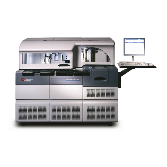
- Page 42 System Description Sample Handling System Figure 1.1 UniCel DxC 600/800 Analyzer (600 shown) A011869P.EPS 1. Modular Chemistry (MC) Section 4. Dual Reagent Carousel 2. Cartridge Chemistry (CC) Portion 5. Operator Console 3. Autoloader Sample Handling System Introduction The Sample Handling system is composed of the following components: •...
- Page 43 2.0 mL cups Capillary collection tubes (use with the capillary tube adapter) Beckman Coulter Microtubes 16 × 100 16 × 100 mm tubes 16 × 92 mm tubes 16.5 × 100 mm tubes Beckman Coulter 0.5 mL Cup Insert (PN 467406) A13914AF...
- Page 44 System Description Sample Handling System Rack ID Labels Sheets of bar-coded rack ID labels are supplied with the system. They can be applied as shown in Figure 1.2. Figure 1.2 Rack 1. Numeric Rack ID Number 2. Rack Size Label 3.
- Page 45 System Description Sample Handling System Autoloader/Offload Track When viewed from the front of the system, the autoloader is on the left and holds up to 25 sample racks in preparation for presentation to the DxC 800 system. The DxC 600 system has room to load a maximum of 14 racks.
- Page 46 System Description Sample Handling System Priority Load Button Typically, rack placement and removal is under microprocessor control. The operator may use the reserved positions in the sample carousel by pressing the PRIORITY LOAD button and placing the priority rack in the space provided by the system. The rack loads into one of the reserved positions on the Sample Carousel.
- Page 47 System Description Sample Handling System 1-Blade Thick CTS (Closed Tube Sampling) or 1-Blade Narrow CTS Cap Piercer Assembly (optional) CAUTION This Cap Piercer contains a razor sharp blade assembly. CAUTION To avoid damage to the blade, do NOT use this Cap Piercer assembly with foil-capped tubes.
- Page 48 System Description Modular Chemistry (MC) System Sample Carousel The ten-rack position Sample Carousel is a motor-driven turntable. Refer to Figure 1.4. Under normal operation, eight of the Sample Carousel positions are available for routine processing and two positions are reserved for priority racks. Figure 1.4 Sample Carousel Area A015903P.EPS 1.
- Page 49 System Description Modular Chemistry (MC) System Reagent Storage Area The reagent containers used to supply the modular chemistries are located behind the left front door of the system. The only exception is the CO alkaline buffer which is located on the ISE module. Figure 1.5 Modular Chemistry Reagent Storage Area 1.
- Page 50 System Description Modular Chemistry (MC) System Ratio Pump The Ratio Pump is a motor-driven, multicylinder, positive-displacement pump used to deliver the necessary reagents to the ISE flow cell. Refer to Figure 1.6. It consists of a three-step piston housed in three, stacked, independent cylinders. Figure 1.6 DxC 800 Ratio Pump A015904P.EPS 1.
- Page 51 System Description Modular Chemistry (MC) System Electrolyte Injection Cup (EIC) The EIC mixes the sample and buffer prior to delivery of the sample (now diluted) to the flow cell. Figure 1.7 Electrolyte Injection Cup 1. Waste Outlet 4. Reference Inlet 2.
- Page 52 System Description Modular Chemistry (MC) System Flow Cell Assembly The flow cell assembly houses the seven electrodes that perform the analysis of sodium, potassium, chloride, carbon dioxide, and calcium. Figure 1.8 Flow Cell 1. Inlet Port 6. Exit Port for Waste (large tube) 2.
- Page 53 System Description Cartridge Chemistry (CC) Reagent Handling System Chemistry Reaction Modules (Basic Components) Each of the six Chemistry Reaction Modules have similarities in their design. These common elements are described below. Refer to Figure 1.9. Unique design elements of the modules are described under the specific module headings later in this section.
- Page 54 System Description Cartridge Chemistry (CC) Reagent Handling System Reagent Cartridges Reagent cartridges are single use, recyclable plastic containers that house the individual liquid reagent components necessary to perform a chemistry test. The reagent carousel is capable of storing 59 cartridges on board. Figure 1.10 CC Reagent Cartridge 1.
- Page 55 System Description Cartridge Chemistry (CC) Reagent Handling System Reagent Carousel and Reagent Bar Code Readers The Reagent Carousel Compartment provides an on-instrument storage area for the individual reagent cartridges. A total of 59 reagent cartridges can be stored in the carousel at one time. Refer Figure 1.11.
- Page 56 System Description Cartridge Chemistry (CC) Reagent Handling System Reagent Probe Assembly The Reagent Probe assembly consists of a mechanical structure that supports two moveable cranes. Attached to each crane is a pickup probe. Refer to Figure 1.12. Figure 1.12 CC Reagent Probe Area A015908P.EPS 1.
- Page 57 System Description Cuvette Reaction System Cuvette Reaction System Introduction The Cuvette Reaction system consists of the following components: • Reaction carousel assembly • Photometer assembly • LPIA (Large Particle Immuno Assay) or NIPIA (Near-Infrared Particle Immuno Assay) module (optional) • Cuvette wash station The Cuvette Reaction system involves the process of obtaining absorbance readings from each cuvette during the analysis cycle.
- Page 58 System Description Cuvette Reaction System Figure 1.13 Reaction Carousel Area (Typical – Cover Removed) A015909P.EPS 1. LPIA Module (optional) 2. Reaction Carousel 3. Photometer Photometer Assembly Attached to the reaction carousel support frame is the Photometer assembly. This consists of a xenon pulse lamp, a discrete 10-position silicon-diode detector array, a monochromator housing unit, and associated electronic circuitry.
- Page 59 System Description Cuvette Reaction System Cuvette Wash Station The Cuvette Wash Station, (refer to Figure 1.14), consists of four coaxial probes, an elevator assembly, and the associated tubing. A motor controls the vertical motion required by the elevator to raise and lower the probes during the wash stage.
- Page 60 System Description Hydropneumatic System Hydropneumatic System Introduction The main components of the Hydropneumatic System are mounted on a slide-out drawer that allows for easier operator access. Refer to Figure 1.15 Figure 1.16. When fully extended, the drawer locks open. To close, lift up on the metal tabs, located on each side of the bottom runner of the hydropneumatic unit, and push the drawer inward.
- Page 61 System Description Hydropneumatic System Function The function of the hydropneumatic system is to provide the following media to the different functional areas of the instrument: • Vacuum • Compressed air • Diluted wash solution • Deionized water Figure 1.16 DxC 800 Hydropneumatics (left side) A015911P.EPS 1.
- Page 62 System Description Operation and Control Components Operation and Control Components Operator Controls The operator interfaces with various control devices such as the keyboard, monitor and push- button controls during a routine run. Basic operating functions are controlled and reviewed from the monitor.
- Page 63 System Description Main Screen and Program Structure Main Screen and Program Structure Main Screen DxC System operating and programming functions are initiated from the screen at the DxC Main analyzer (refer to Figure 1.17). In addition, the screen provides status information to help determine the present state of the system.
- Page 64 System Description Main Screen and Program Structure Status Functions The following Table depicts the status information available from the operator screens of the DxC analyzer. Table 1.13 Main Screen Status Functions Status Indicator Status Description This indicator (1) in Figure 1.17, appears in the blue bar at the top left side of the Operator screens when the Closed Tube Sampling (CTS) option is installed.
- Page 65 System Description Main Screen and Program Structure Sample Status Indicators Refer to Figure 1.17. When monitoring sample status, a sample status icon appears in front of listed samples. Samples are listed in a rack status box directly below the sample status icon legend (5). The sample statuses shown are as follows: Table 1.14 Sample Status Indicators Status Indicator...
- Page 66 System Description Main Screen and Program Structure Menu Bar Icons and Program Structure Near the top of the Operator screens, a series of icons on the touch screen provide access to each of the major functional areas of the system (4) (refer to Figure 1.17).
- Page 67 System Description Main Screen and Program Structure Figure 1.19 Program Structure (Results, Rgts/Cal) 1-31 A13914AF...
- Page 68 System Description Main Screen and Program Structure Figure 1.20 Program Structure (QC, Setup) 1-32 A13914AF...
- Page 69 System Description Main Screen and Program Structure Figure 1.21 Program Structure (Setup - continued) 1-33 A13914AF...
- Page 70 System Description Main Screen and Program Structure Figure 1.22 Program Structure (Setup - continued) 1-34 A13914AF...
- Page 71 System Description Main Screen and Program Structure Figure 1.23 Program Structure (Utils) 1-35 A13914AF...
- Page 72 System Description Main Screen and Program Structure Figure 1.24 Program Structure (Utils – continued) 1-36 A13914AF...
- Page 73 System Description Main Screen and Program Structure Figure 1.25 Program Structure (Utils – continued, Status, Instr Cmd, and Help) 1-37 A13914AF...
- Page 74 System Description Main Screen and Program Structure Recall Results for On-board Samples To preview the results of tests In Progress, before the rack is unloaded from the system, perform the following procedure. Select the sample for the desired results. The sample is highlighted. Select .
- Page 75 System Description Main Screen and Program Structure Rack Status Area These boxes, Figure 1.17 (6), represent the ten possible rack locations on the Sample Carousel. As each rack is loaded, the rack number is displayed at the top of the Rack Status box. All sample IDs on the rack are listed below the rack number.
- Page 76 System Description Main Screen and Program Structure The samples in the log are arranged in a first in, first out sequence. When a new sample comes in at the top of the list, the other sample(s) move down one space. Samples will remain on the list until their status changes to "Complete"...
- Page 77 System Description Main Screen and Program Structure Table 1.16 Sample Log Fields (Continued) Field Description • If there are two results because of a Critical Sample Rerun, the log entry Status shows: — Review Results • If an incomplete sample is removed from the sample carousel, the log entry shows one of the following status indications: —...
- Page 78 System Description Main Screen and Program Structure Pre Run Summary The Pre Run Summary is a printed report containing summary information about the programmed tests for each chemistry. This information helps in determining the status of the reagents to verify that the system is in a condition to complete the requested tests.
-
Page 79: Theory Of Operation
System Description Theory of Operation Theory of Operation Introduction The UniCel DxC Synchron Clinical Systems are microprocessor-controlled, random access clinical analyzers capable of processing a wide variety of operator-selected chemistries in a single run. Cartridge Chemistries (CC) The optical system of the DxC enables rate, endpoint, and nonlinear analyses to be performed simultaneously. - Page 80 System Description Cartridge Chemistry: Calibration Theory Endpoint and First-Order Chemistries Calibration of endpoint and first-order rate chemistries involve the use of a single-level calibrator solution or a two-level calibrator kit. Each analyte in the calibrator solution has a known concentration value associated with it. With each new lot of calibrator solution, the values are transferred from disk and stored in memory for later use in the calibration procedure.
- Page 81 System Description Cartridge Chemistry: Calibration Theory Table 1.17 Calculation of Calibration Factors for Endpoint and Rate Chemistries Type Formula Nonblanked FOR HIGH CALIBRATOR LEVEL: Endpoint Reaction ABS = ABS rep1 Chemistries Reaction ABS = ABS rep2 (ABS + ABS ) × 0.5 = ABS (hi) rep1 rep2...
- Page 82 System Description Cartridge Chemistry: Calibration Theory Table 1.17 Calculation of Calibration Factors for Endpoint and Rate Chemistries (Continued) Type Formula Blanked Endpoint FOR HIGH CALIBRATOR LEVEL: Chemistries (with Volume Blank Volume Correction) Blank Correction Factor = Total Reaction Volume Volume of Reagent(s) (and Sample) at Blank Read Volume of Total Reagent and Sample at Reaction Read E007123L.EPS [Reaction ABS - (Blank ABS ×...
- Page 83 System Description Cartridge Chemistry: Calibration Theory Table 1.17 Calculation of Calibration Factors for Endpoint and Rate Chemistries (Continued) Type Formula Nonblanked Rate FOR HIGH CALIBRATOR LEVEL: Chemistries Reaction Rate = Rate rep1 Reaction Rate = Rate rep2 (Rate + Rate ) ×...
- Page 84 System Description Cartridge Chemistry: Calibration Theory Table 1.17 Calculation of Calibration Factors for Endpoint and Rate Chemistries (Continued) Type Formula Blanked Rate FOR HIGH CALIBRATOR LEVEL: Chemistries (Reaction Rate - Blank Rate) = Delta Rate rep1 (Reaction Rate - Blank Rate) = Delta Rate rep2 (Delta Rate + Delta Rate...
- Page 85 System Description Cartridge Chemistry: Calibration Theory Table 1.17 Calculation of Calibration Factors for Endpoint and Rate Chemistries (Continued) Type Formula Blanked Rate FOR HIGH CALIBRATOR LEVEL: Chemistries (with Volume Blank Volume Correction) Blank Correction Factor = Total Reaction Volume Volume of Reagent(s) (and Sample) at Blank Read Volume of Total Reagent and Sample at Reaction Read E007123L.EPS [Reaction Rate - (Blank Rate ×...
- Page 86 System Description Cartridge Chemistry: Calibration Theory Non-Linear Chemistries Non-linear chemistries include drugs and specific protein assays. Unlike the first-order rate and endpoint chemistries, which exhibit a linear response to increasing concentration, the calibration curves for non-linear chemistries exhibit logarithmic (S-shaped) or other nonlinear relationships. For this reason, curve fitting interpolation techniques are employed to construct the calibration curve.
- Page 87 System Description Cartridge Chemistry: Calibration Theory Table 1.18 Math Models for Non-Linear Chemistries Type Formula Model #1 Math Model #1 is the four-parameter log-logit function most commonly used with reagents that use antibodies. Sample values are determined using the calculated curve parameters and the math model.
- Page 88 System Description Cartridge Chemistry: Calibration Theory Table 1.18 Math Models for Non-Linear Chemistries (Continued) Type Formula Model #9 Math Model #9 is an extension to model #1, the four-parameter log-logit function. The "c" is allowed to be either +1 or -1. If c = +1, then this is equivalent to model #1.
- Page 89 System Description Modular Chemistry: Calibration Theory Drugs of Abuse Testing (DAT) Chemistries The Drugs of Abuse Testing (DAT) assays require three levels of calibrators. The calibration measures the separation between calibrators to measure reagent integrity. The calibration factor generated is non-functional for sample result calculation. The cutoff value for each DAT chemistry represents the mean reaction rate of the low calibrator, reported in mA/min units on patient and control reports.
- Page 90 System Description Cartridge Chemistry: Principles of Measurement Table 1.19 Methodology and Modules Used with Modular Chemistries Chemistry Methodology Module Sodium Ion selective electrode (ISE) ISE Flow cell Potassium Ion selective electrode ISE Flow cell Chloride Ion selective electrode ISE Flow cell Carbon Dioxide pH electrode ISE Flow cell...
-
Page 91: Overview,
CHAPTER 2 Preparing Samples for Analysis Routine Operation Overview Daily Procedure The following procedure shows an example of daily work flow using the UniCel DxC Synchron Clinical System. IMPORTANT This procedure assumes that the initial system setup has been completed. If necessary, start the system. - Page 92 16 × 100 16 × 100 mm tubes 16.5 × 92 mm tubes Beckman Coulter 0.5 mL Cup Insert (PN 467406) IMPORTANT Adapters are provided to adapt various sized sample tubes (secondary tubes) to the short racks. These adaptors must only be used in racks designated as reserved. The reserved rack feature is described in this chapter.
- Page 93 • For CTS systems, remove the cap, if not a validated closed tube. • Determine sufficient volume. Secondary Tube • Check for fibrin or other materials resulting from storage. Beckman Coulter Synchron • Place into a 13 × 100 mm rack. Microtube • Pipette the sample into a Synchron Microtube.
- Page 94 Preparing Samples for Analysis Preparing Samples for Analysis Bar Code Labeling The use of bar code labels is a highly accurate and efficient method for identifying and processing laboratory samples. However, the system must be able to identify and read every bar code label to process each sample correctly.
- Page 95 DI water. When running in the CTS mode, if tubes off-loaded from the UniCel DxC Systems have water or droplets of water on the caps, disable the CTS and contact Beckman Coulter Support Center. Note: Oil on a cap is normal. Closed Tube Sampling (CTS) This is an optional feature that allows the system to pierce primary sample tubes.
- Page 96 Preparing Samples for Analysis Preparing Samples for Analysis • If a Sample ID is reused for an unpierced sample, clear the Sample ID on the instrument, the cap does not need to be removed. • If you need to clear the CTS database (for example, if the host system's counter rolls over and uses the same Sample IDs again), clear the Sample IDs at any of the instruments connected by the tracking network.
- Page 97 Preparing Samples for Analysis How to Use Reserved Racks How to Use Reserved Racks When NOT to Use a Reserved Rack When you use CTS (Closed Tube Sampling), do NOT run a closed tube in a reserved rack. Reserved Racks If a rack number is entered into this field, any sample containers in this rack will not be cap pierced even if the Cap Piercing feature is enabled.
- Page 98 Preparing Samples for Analysis How to Use Reserved Racks Assigning or Reassigning Reserved Racks Select from the menu bar. Setup Select on the right side of the screen. Page Down Select . The following screen appears. 17 Reserved Racks/Obstruction Detection Figure 2.2 Reserved Racks/Obstruction Detection Setup Dialog Box E015928S.EPS Type the rack numbers to assign as reserved racks in the HbA1c and IBCT fields.
- Page 99 CHAPTER 3 System Setup Options Overview Introduction This chapter summarizes the 29 System Setup options depicted on the screens shown in Setup Figure 3.1 Figure 3.2 below: Figure 3.1 Setup Screen (scrolled to the top) E011951S.EPS A13914AF...
-
Page 100: Password Setup,
System Setup Options Password Setup Figure 3.2 Setup Screen (scrolled to the bottom) E015931S.EPS For detailed step-by-step instructions on using the System Setup option, refer to the UniCel DxC Synchron Clinical Systems Reference Manual. Password Setup Introduction The Password Setup option allows the operator to: •... - Page 101 System Setup Options Password Setup Defining/Editing Password Setup To define, edit or delete user names, passwords, privilege levels and accessibility levels, follow the procedure below. Select from the menu bar. Setup Select from the screen. 28 Password Setup Setup Enter an Administrator password in the dialog box.
-
Page 102: Auto Serum Index/Ordac,
IMPORTANT The analytical ranges for each analyte are system limits found in the respective CISs. These are the ranges that Beckman Coulter has verified can be achieved by the system. There is no flagging associated with values exceeding these limits. -
Page 103: Menu,
Down, or Homing. Configuring a Beckman Coulter Chemistry The chemistry menu, available in sample programming, quality control, panel definition and other screens, is defined by the user. To define Beckman Coulter chemistries, select 2 Chemistry from the screen. Place the cursor in an open field in the... - Page 104 (QC) information from the instrument before deleting the chemistry from the system. Where it is used, Beckman Coulter recommends that you remove chemistries from the system following the sequence and procedures below to prevent problems with deleting chemistries from...
- Page 105 System Setup Options Configuring the Chemistry Menu Remove calibrator assignments. To clear calibrator bar code ID and/or rack and position: • Select Assign F7 • Select to locate the calibrator of interest. Next Prev • Select the pull-down menu at the top of the dialog box Calibrator Name Assign Barcode/Rack...
- Page 106 System Setup Options Configuring the Chemistry Menu Select to show the load list on the screen. The Load List may then be printed by selecting Display to print, or to exit. Print Repeat Steps 2–5 in this section to request load lists for samples in the Incomplete and Rerun status.
- Page 107 System Setup Options Configuring the Chemistry Menu If the control definition contains the chemistry along with other chemistries that should not be deleted, a single chemistry definition can be deleted. Select from the menu bar. From the screen, select a control number. Select Define F2 Select...
- Page 108 Samples. If not, patient samples are purged during rollover at 10,000 Patient IDs or 150,000 results, whichever comes first. Beckman Coulter Defined Chemistries with Units and Precision Table 3.1 UniCel DxC 600/800 Beckman Coulter Defined Chemistries with Acronyms Units and Precision Beckman Coulter Defined Chemistry...
- Page 109 System Setup Options Configuring the Chemistry Menu Table 3.1 UniCel DxC 600/800 Beckman Coulter Defined Chemistries with Acronyms Units and Precision (Continued) Beckman Coulter Defined Chemistry Acronym Units Precision Complement C4 mg/dL C-Reactive Protein mg/dL C-Reactive Protein C-RP mg/dL X.XX...
- Page 110 System Setup Options Configuring the Chemistry Menu Table 3.1 UniCel DxC 600/800 Beckman Coulter Defined Chemistries with Acronyms Units and Precision (Continued) Beckman Coulter Defined Chemistry Acronym Units Precision Microprotein M-TP mg/dL Opiate (2000 ng/mL cutoff) mA/min X.XX Opiate (300 ng/mL cutoff) mA/min X.XX...
-
Page 111: Date/Time Setup,
System Setup Options Setting the Default Sample Type Setting the Default Sample Type Introduction Default Sample Type allows for definition of the default sample type for all programmed samples. The sample type may be changed for individual samples while in the sample programming function. Setup To set the default sample type, select from the... -
Page 112: Setup,
System Setup Options Demographics Setup IMPORTANT Changes to system date and/or time may affect reagent expiration date, calibration, quality control data, within-lot calibration status, and on-board stability dates for reagents. Demographics Setup Introduction The Demographics Setup option provides the ability to select the demographics fields that appear in the demographics display/printout of the Program Samples function. -
Page 113: Panels,
System Setup Options Panels Select to send to the Host and/or printer any Critical Result Immediate Report of Critical Rerun Rerun as soon as it is completed. Select to send to the Host and/or printer any Serum Index result Immediate Report of Serum Index as soon as it is completed. -
Page 114: Replicates,
System Setup Options Replicates Replicates Introduction The Replicates option allows the operator to set up the number of replicates per sample, which is applied to all sample programs. The replicates per sample may also be edited by accessing a specific sample program. - Page 115 • Instrument Printable Range • Reportable Range Analytical Range The Analytical Range is an internal system limit verified by Beckman Coulter. Refer to the Synchron Clinical Systems Chemistry Information Manual and the Synchron Clinical Systems Chemistry Reference Manual for Analytical Ranges by analyte.
- Page 116 The Reportable Range feature is available on all configured chemistries except drugs of abuse (DAT) and Beckman Coulter Performance Verification Tests (PVT). The Reportable Range feature is available for User Defined Reagents (UDR). When any UDR parameter is edited, the instrument automatically changes the Reportable Range information to the Usable Range defined for the UDR.
- Page 117 System Setup Options Reference/Critical Ranges Setup Reference/Critical Ranges Setup Reference and Critical Ranges Reference and Critical Range Setup options allow the operator to define the reference and critical ranges for each analyte by age group, gender and sample type. Up to 32 age ranges may be defined. In addition, the operator may select one reference range as the default.
-
Page 118: Definition,
Special Calculations Definition Introduction The two types of Special Calculations that can be reported with a sample are: • Predefined by Beckman Coulter • Operator defined The system can maintain up to 40 special calculations. You can enable or disable the predefined special calculations, but you cannot modify or delete them from the system. - Page 119 Serum Hemoglobin A1c2 SI mmol/mol Blood Beckman Coulter Predefined Special Calculation Formulas Table 3.3 UniCel DxC 600 Predefined Special Calculation Formulas Calculation Formula Osmolality (1) (1.86 × NA) + (GLUCm/18) + (BUN/2.8) + 9 Osmolality (2) (1.86 × NA) + (GLUCm/18) + (UREA) + 9...
- Page 120 System Setup Options Special Calculations Definition Table 3.3 UniCel DxC 600 Predefined Special Calculation Formulas (Continued) Calculation Formula ApoA/ApoB Ratio ApoA/ApoB ApoB/ApoA Ratio ApoB/ApoA HbA1c A1c/Hb × 100 HbA1c2 A1c2/Hb2 × 100 HbA1c SI A1c/Hb x 1000 HbA1c2 SI A1c2/Hb2 x 1000 a.
-
Page 121: Version Information,
System Setup Options Timed Urine and Creatinine Clearance Results Timed Urine and Creatinine Clearance Results Introduction When Timed Urine is designated as the sample type for a Sample ID, the Results report will reflect: • the concentration of the sample aliquot placed on the instrument. •... - Page 122 System Setup Options Units/Precision Setup Units/Precision Setup Introduction The Units/Precision option allows the operator to select the units and number of decimal places for each viewed and printed result. When the units are altered, all features affected by the change, such as reference ranges and calibration values, automatically convert to match the new units.
-
Page 123: Bar Code Setup,
System Setup Options Bar Code Setup Bar Code Setup Introduction The Bar Code Setup option allows the operator to: • Enable/disable sample bar code mode of operation • Enable/disable sample bar code types • Configure sample bar code parameters • Restore defaults The four sample bar code types that may be used on the DxC are: •... -
Page 124: Age,
System Setup Options Maximum Sample Program Age Maximum Sample Program Age Introduction This feature refers to the age of the sample program. The operator may define the time limit allowed before the same sample ID can be reloaded on the system. The operator is notified of the time conflict by a pop-up window when the time limit has been exceeded. -
Page 125: Monitor,
System Setup Options Disable Service Monitor Setup From the screen, scroll down and select to enable/ Setup 17 Reserved Racks/Obstruction Detection disable CTS, enable/disable obstruction detection, assign reserved rack numbers for small sample volume containers, HbA1c or IBCT, or to restore defaults. The system must be in Standby, Stopped, Startup, Instrument Down, or Homing to make modifications. -
Page 126: Host Communications,
System Setup Options Host Communications Host Communications Introduction Table 3.5 following lists the Host communications parameters, the options of each, and the default values. Table 3.5 DxC Host Communications Parameter Options for ASTM, LX20/DxC, CX7 Compatible Parameter Serial Options TCP/IP Options Default Transport Serial or TCP/IP... - Page 127 System Setup Options Language/Keyboard Setup Setup From the screen, scroll down and select to select parameters or Setup 20 Host Communications restore defaults. The system must be in Standby or Stopped to make modifications. Refer to the UniCel DxC Synchron Clinical Systems Host Interface Specifications for comprehensive documentation for the host parameters.
-
Page 128: Printer Setup,
Service Setup feature, the menu bar is green. After exiting from Service Setup the screen returns to normal. Enabling Service Setup This feature is password protected and can only be accessed by Beckman Coulter personnel. Disabling Service Setup The Service Monitor mode can be disabled at any time. Refer to... -
Page 129: System Configuration,
The instrument serial number is also shown in this area. View/Edit System Configuration This feature is password protected and can only be accessed by Beckman Coulter personnel. CAUTION Changes to the information in this area should only be done at the request or at the direction of Beckman Coulter, Inc. -
Page 130: Status Alarm/Annunciator,
System Setup Options Status Alarm/Annunciator Status Alarm/Annunciator Introduction The Status Alarm/Annunciator option allows the operator to: • Select from 5 different audible alarm patterns • Test the audible alarm • Disable the audible alarm Setup From the screen, scroll down and select to select an alarm Setup 26 Status Alarm/Annunciator... -
Page 131: Control,
System Setup Options Auto Generation of Control Auto Generation of Control Introduction When this feature is enabled, if a sample is loaded with a defined control ID, the instrument will automatically run any chemistry that is on-board and runnable for that control. When Auto Generation of Control is enabled, the automatic Multiple Cartridge option is available. - Page 132 System Setup Options Auto Generation of Control 3-34 A13914AF...
-
Page 133: Reagent Load/Calibration,
CHAPTER 4 Reagent Load/Calibration Reagent Load Introduction This chapter describes how to load reagents onto the DxC 800 and DxC 600 systems and calibrate chemistries using the screen. The DxC system loads and removes both Reagent Load/Calibration cartridge (CC) and modular (MC) chemistries bulk reagents. Reagent information encoded on the container label can be read by the bar code reader or entered manually from the keyboard. - Page 134 Reagent Load/Calibration Reagent Load Pre-Run Checklist Before testing samples, generate a Pre-Run Checklist to determine if reagents should be loaded or calibrated. From the screen, select or select . Select Main Pre-Run F9 Rgts/Cal Print F10 Rgts/Cal Screen Overview If the icon is red or yellow, select it and look for chemistries that are highlighted red or Rgts/Cal yellow.
- Page 135 Reagent Load/Calibration Reagent Load Table 4.1 Reagent Status Messages (Continued) Message Explanation Level Pending Reagent cartridge has been loaded and is waiting to be level-sensed. Level Sense Error Level sense check failed to properly detect reagent in one or more compartments.
- Page 136 Reagent Load/Calibration Reagent Load Load/Unload Reagent MC Reagents Information The DxC System loads and unloads Modular Chemistries (MC) using the bar code system. The reagent bar code information includes: • Serial Number • Lot Number • Expiration Date • Reagent Name Figure 4.2 MC Reagent Information A015919P.EPS 1.
- Page 137 Reagent Load/Calibration Reagent Load Figure 4.3 DxC 800 Leftmost Compartment 1. BUNm/UREAm 6. CREm 2. PHOSm 7. Electrolyte Buffer 3. GLUCm 8. Electrolyte Reference 4. TPm 9. CO Acid 5. ALBm Figure 4.4 DxC 600 Leftmost Compartment 1. GLUCm 3. Electrolyte Buffer 2.
- Page 138 Reagent Load/Calibration Reagent Load Figure 4.5 DxC 600/800 Center Compartment A015922P.EPS 1. Wash Concentrate II 2. No Foam solution 3. CTS Auto-Gloss Modular chemistry reagent bottles are selected from the screen and replaced as necessary Rgts/Cal according to volume. Reagent volume levels are automatically tracked by the system after the initial volume is set.
- Page 139 Reagent Load/Calibration Reagent Load CAUTION To avoid contamination, do NOT touch the reagent straw. NOTE The No Foam container shown in Figure 4.6 (2) is refilled by pouring a fresh bottle of No Foam solution into the empty container on the instrument. Refer to Figure 4.6 and refill the No Foam container as follows:...
- Page 140 Reagent Load/Calibration Reagent Load Use the hand-held bar code reader to scan the reagent bar code of each new bottle. The system "beeps" to indicate a successful bar code read. Check the monitor to verify that the reagent data shows. When the bar code is scanned, the reagent screen updates with current reagent information.
- Page 141 Reagent Load/Calibration Reagent Load Figure 4.8 CC Reagent Information 1. Reagent Name 3. Expiration Date 2. Lot Number 4. Serial Number Load/Unload Cartridge Chemistries (CC) Select from the menu bar. Rgts/Cal Select all positions to be loaded or unloaded. The selected positions are highlighted. Use the up and down arrows to access screens for additional chemistries.
- Page 142 Reagent Load/Calibration Reagent Load Figure 4.9 Reagent Carousel A011871P.EPS 1. Cartridge 2. Top Positions 3. Bottom Positions To load reagent: • When the screen prompts you to load the cartridge, open the reagent carousel door. Move the cartridge in front of the bar code reader. A beep will indicate that the bar code is read. •...
- Page 143 Reagent Load/Calibration Reagent Load • can be loaded using the hand-held bar code reader or loaded manually. Load Reagent Parameters Select from the menu bar. Rgts/Cal NOTE If parameters are loaded as part of the reagent cartridge load, proceed directly to Step 3. Select Params F2 NOTE...
-
Page 144: System Calibration,
Reagent Load/Calibration System Calibration System Calibration Introduction System calibration is used to standardize the analysis of samples to existing conditions. Refer to the Synchron Clinical Systems Chemistry Information Manual for detailed information regarding such conditions. In general, system calibration is required when: •... -
Page 145: Calibrator Assignment,
Reagent Load/Calibration Calibrator Assignment Limits.” To find the calibrator, use either the button or use the pull-down menu Prev Next and select the calibrator name. • To load a new lot number of calibrator, locate the calibrator diskette in the calibrator box and follow the procedure below. -
Page 146: Calibration Status,
Reagent Load/Calibration Calibration Status Select from the menu bar. Rgts/Cal Select Assign F7 Use the down arrow option button to open list of calibrators. Select the calibrator. Enter the ID of the calibrator or the rack/position number. • If using a bar code label, the label must match the assigned calibrator ID. •... -
Page 147: Warnings,
Reagent Load/Calibration Reagent and Calibration Status Warnings Table 4.2 Calibration Status Messages (Continued) Message Explanation Cal Overridden Operator-initiated; results are based on the failed calibration. Chem Bypassed Operator-initiated; allows analysis to proceed on all other chemistries without having to deprogram the bypassed chemistry. A bypassed chemistry can be recalibrated, but not extended or overridden. -
Page 148: Request A Calibration,
Reagent Load/Calibration Request a Calibration Table 4.3 Conditions and Highlights for Calibration Status Warnings (Continued) IF the Calibration Status has... THEN the Highlight Which Means... is... Cal Overridden Yellow The chemistry needs attention, but the process can continue. Cal Time Extended No warning condition or N/A The chemistry is OK and the process —... - Page 149 Reagent Load/Calibration Request a Calibration Place the rack (1) in the autoloader (2) with the rack bar code label to the right. Press on the analyzer. Figure 4.10 A015925P.EPS Calibrate DxC Chemistries Using Assigned Calibrator Racks From the dialog box, check the Calibration Time Left column shown in days:hours:minutes Rgts/Cal and the Cal Status column to see which chemistries require calibration.
-
Page 150: Calibration Failure Messages,
Reagent Load/Calibration Calibration Failure Messages • All other calibrators need 3 drops of calibrator in a 0.5 mL cup. Place the rack (1) in the autoloader (2) with the rack bar code label to the right. Press on the analyzer. Refer to Figure 4.10. -
Page 151: Within-Lot Calibration,
Reagent Load/Calibration Within-Lot Calibration • Chem name • Reagent Position MC Subsystem Calibration Failure The MC Subsystem warns the operator of a failed calibration. If a chemistry fails, a pop-up message appears after a completed calibrator level. The message includes: •... - Page 152 Reagent Load/Calibration Within-Lot Calibration Select Options F6 Select from the pull-down menu. Within lot calibration From the pull-down menu, select a desired Configured Chemistry name. Refer to Figure 4.11. Select to move the chosen Chemistry to the Selected Chemistries area. Repeat Step 5 for other chemistries, if appropriate.
- Page 153 Reagent Load/Calibration Within-Lot Calibration Within-Lot Calibration Status Screen screen has a summary of the within-lot calibration time which Within-Lot Calibration Status remains. This summary is for the cartridge chemistry/lot number combinations that have within- lot calibration factors applied. Select a desired Configured Chemistry name from the dialog box.
- Page 154 Reagent Load/Calibration Within-Lot Calibration Within-Lot Designations The designations wf, w, and ws follow the reagent lot numbers of those chemistries selected for within-lot calibration. These designations are defined below. Table 4.4 Definitions of Within-Lot Designations Designation Description Reagent has been enabled for within-lot calibration and the cartridge has been "freshly"...
-
Page 155: Enzyme Validator,
Reagent Load/Calibration Enzyme Validator IMPORTANT When you start to do a calibration on a fresh cartridge, you must complete it within 8 hours or the within-lot calibration established will be less than optimal. Enzyme Validator Introduction The Enzyme Validator option provides the ability to obtain IFCC/DGKCh (refer to Additional Information below) equivalent answers for selective enzymes, or to obtain IFCC/DGKCh equivalent... -
Page 156: Calibration Override,
Reagent Load/Calibration Calibration Override Additional Information DGKCh (Deutsche Gesellschaft für Klinische Chemie - German Clinical Chemistry Association) IFCC (International Federation of Clinical Chemistry), a committee that establishes formulation standards in Europe. Calibration Override Introduction The Calibration Override option allows the system to override a failed calibration and obtain results based on the failed calibration factors. -
Page 157: Chemistry Bypass,
Reagent Load/Calibration Chemistry Bypass Chemistry Bypass Introduction In the event of a calibration failure for a chemistry which has been previously sample programmed, Chemistry Bypass permits the continuation of analysis of all other programmed tests without having to deprogram a failed chemistry. The chemistry can be bypassed while the system status is Standby, Disabled or Running. -
Page 158: Extend Calibration Time,
Reagent Load/Calibration Extend Calibration Time Extend Calibration Time Introduction The Extend Calibration Time option allows the extension of a calibration that has exceeded the recommended calibration time. The system shows a warning message approximately fifteen minutes prior to the calibration timeout. At this point, the operator can recalibrate the chemistry in question or extend the calibration time. -
Page 159: Limits,
Reagent Load/Calibration Calibration Acceptance Limits Calibration Acceptance Limits Introduction Calibration absorbance or ADC values are compared to preprogrammed back-to-back, span, and range limits to determine acceptable performance. If calibration errors in accuracy, precision, sensitivity, or linearity are detected by the system computer, error flags are generated. Calibration Acceptance provides a reference to the acceptable limits for calibration. -
Page 160: Calibrator Set Point Modifications,
Reagent Load/Calibration Calibrator Set Point Modifications Calibrator Set Point Modifications Introduction The Calibrator Set Point Modifications option allows editing of the programmed calibrator set points. This option can be used to alter any chemistry provided it: • has calibration data. •... -
Page 161: Slope Offset Adjustment,
Reagent Load/Calibration Slope Offset Adjustment Move the cursor to the set point to be modified and type the desired value. • If a previously modified set point is to be returned to the original default value for that calibrator or chemistry, select desired chemistry, move cursor to the applicable set point and select Restore Defaults •... - Page 162 Reagent Load/Calibration Slope Offset Adjustment Slope Offset Recommendations When slope and offset modification is desired, the slope and offset values to be used must be experimentally derived from statistically significant patient correlation studies. It is recommended that patient samples are run over a period of several days by both methods, using controls to monitor accuracy.
-
Page 163: Reprint Calibration Reports,
Reagent Load/Calibration Reprint Calibration Reports Move cursor to the slope and/or offset to be modified. Press from the keyboard or use the screen scroll bar to locate the Page Up Page Down Chem. Type the desired value in the appropriate fields. - Page 164 Reagent Load/Calibration Reprint Calibration Reports Reprint Previous Calibration Reports Select from the menu bar. Rgts/Cal Select Options F6 Select from the pull-down menu. Print cal report Select from the dialog box. Previous cal report(s) Print cal report Select the desired Configured Chemistry name(s) from the dialog box.
-
Page 165: Quality Control,
CHAPTER 5 Quality Control Quality Control Introduction This task is performed when your laboratory protocol indicates that control material should be analyzed. A daily analysis of at least two levels of control materials is highly recommended. In addition, these controls should be run with each new calibration, with each new lot of reagents, and after specific maintenance or troubleshooting activities. - Page 166 Quality Control Quality Control X = the individual control result X = the assigned mean for the control SD = the assigned standard deviation for the control X - X E014425L.EPS Each time a control result is received, the Z-score is calculated. If the Z-score is less than ± 2 SD, the result is within the assigned control range (the assigned mean ±...
- Page 167 Quality Control Quality Control Flags Generated on Printed QC Reports These flags appear in the remarks column of the QC results report: • Greater than 2SD • Greater than 3SD • ACC (Accuracy) two successive controls greater than 2SD • PRE (Precision) two successive controls greater than 2SD on opposite sides of the assigned mean •...
-
Page 168: Define A Control,
Quality Control Define a Control When defining controls, Control IDs should be as descriptive as possible. Refer to the UniCel DxC Synchron Clinical Systems Reference Manual for further details. The following procedures describe how to run control samples. Define a Control Introduction The operator may define up to 100 controls. - Page 169 Quality Control Define a Control Select from the menu bar. Select a control number from the dialog box. Select Define F2 Type the name of the control to be defined in the field. The control name must Control Name be unique with a maximum of 20 alphanumeric characters. NOTE When defining control names, avoid the following characters used by ASTM standard delimiters: •...
- Page 170 Quality Control Define a Control Type the following information in the appropriate fields for all chemistries shown: Field Description QC File Number Type a QC file number for each chemistry. • The QC file number must be a unique 3-digit number from 1 to 999. •...
-
Page 171: Control Id Assignments,
Quality Control Control ID Assignments Control ID Assignments Introduction to Assignment of QC Bar Codes A maximum of eight bar codes (control IDs) per control may be defined. Assignment of bar code IDs is mandatory for Auto Generation of controls. Assignment of QC Bar Codes Select from the... - Page 172 Quality Control Run Control Samples Run Control Samples With Bar Code Labels and Auto Generation of Control Enabled Place bar-coded control samples in rack. All tube bar code labels must be visible through the slots on the same side of the rack as the rack bar code label. When Auto Generation of Control is enabled, the automatic Multiple Cartridge option is available.
-
Page 173: Edit A Control Definition,
Quality Control Edit a Control Definition Select the number next to the field to select from predefined Control Names. If Control Name necessary, use the scroll bar to view additional Control Names. Type the number in the field. screen opens. Make sure the Control Lot number on the screen is the same Program Control as the lot number on the Control bottle. - Page 174 Quality Control Edit a Control Definition Modify Assigned Mean, Assigned SD or Constituent Code Select from the menu bar. Select the control number beside the and select Control Name Define F2 Select the field for modification. Type the modified assigned mean, standard deviation (1 SD), or constituent code. dialog box prompts the operator to choose how the changes will be applied Define/Edit Control to subsequent data.
- Page 175 Quality Control Edit a Control Definition Type the following information in the appropriate fields for all chemistries shown: Field Description QC File Number Type a QC file number for each chemistry. • The QC file number must be a unique 3-digit number from 1 to 999. •...
-
Page 176: Review A Control Definition,
Quality Control Review a Control Definition Review a Control Definition Introduction A control definition can be reviewed from either current QC data or archived QC data. Archived QC data may not be modified, only printed. Current QC data may be reviewed, deleted, or printed. Review a QC Select from the menu bar. -
Page 177: Print Qc Ranges,
Quality Control Print QC Ranges Delete a Control Select from the menu bar. Select the control to be cleared. Select Delete F3 The following message appears to confirm the clearing of the selected control: "All QC files for control will be deleted. Archiving is suggested. Delete this control?" •... -
Page 178: Qc File List,
Quality Control QC File List QC File List Introduction QC File List allows the operator to view and/or print a list of QC files by control name, chemistry name or QC file number. The QC File List is accessible from either Current QC data or Archived QC data. -
Page 179: Qc Summary,
Quality Control QC Summary QC Summary Introduction • The QC Summary report contains the mean, SD, CV and number of results (N) for any control run within a specified date interval. The printed report contains the cumulative mean, SD, CV and (N)umber of accumulated results. -
Page 180: Qc Chart (Levey-Jennings),
Quality Control QC Chart (Levey-Jennings) QC Chart (Levey-Jennings) Introduction QC Chart shows the results of a control for a specified period (default is current date) in a graphic form, showing the position of data points relative to the assigned mean and standard deviation. The results are listed by date and time, most recent results first. - Page 181 Quality Control QC Chart (Levey-Jennings) The chemistries defined for the selected control are listed. All chemistries appear to be selected. For convenience, there are two ways to select the chemistries to chart: • To chart most of the chemistries shown, select all chemistries which should NOT be charted.
- Page 182 Quality Control QC Log QC Log Introduction QC Log shows results with information about the relationship of those results to the assigned mean, SD and previous results for a specified data interval. Also shown are data point deletions. The QC Log may be viewed and/or printed from either the hard disk or the diskette.
- Page 183 Quality Control QC Log The QC Log may be viewed by Chemistry or by Reagent Lot. The default view is in alphabetical order by chemistry, with most recent data entries first. Also shown are the date, time run, result, units, and interpretation of the data (relationship of the result to the assigned mean and previous results).
- Page 184 Quality Control QC Log The following message appears verifying the deletion of the data point: "QC data point will be deleted. Archiving is suggested. Delete QC data point?" • Select to delete the data point. • Select to retain the data point. Cancel The data point will still appear within the QC Log.
- Page 185 Introduction The QAP Copy to Disk feature allows QC data to be copied to a DOS-formatted diskette. This data can then be uploaded to the Beckman Coulter website for processing as part of the Inter-laboratory QC data reduction program. Create a QAP Disk...
- Page 186 If necessary, repeat Steps 2 to 12 above to add additional data to the same diskette. Otherwise, you may go to any screen using the menu bar icons. The diskette is now ready for data to be uploaded to the Beckman Coulter website. 5-22...
-
Page 187: Archive Qc,
Quality Control Archive QC Archive QC Introduction The Archive QC function archives control definition (control name, lot number, sample type, QC File number, QC Log selected chemistries, assigned mean and SD, constituent code, and cumulative mean, SD and N) and results to a diskette. Archiving is available from the hard disk only. The archived diskette can be used to review data, but not to modify QC files. -
Page 188: Review Archived Data,
Quality Control Review Archived Data Insert a disk and select at the prompt when ready. The disk will be formatted by erasure, then the QC data will be archived to it. CAUTION When QC data is deleted from the hard disk, no modifications are allowed. NOTE When archiving is complete, a prompt will ask the operator if QC data should be deleted from the hard disk. - Page 189 Quality Control Review Archived Data Select 2, Review Disk Type and press Enter Insert the archive disk and select at the prompt. Information about the archive disk (date archived, operator ID, start date, end date) appears. • If the information indicates that the proper disk was entered, —...
- Page 190 Quality Control Review Archived Data 5-26 A13914AF...
- Page 191 CHAPTER 6 Sample Programming and Processing Overview Introduction Sample programming provides the ability to identify samples, select tests to run, describe samples, and designate how to run samples. Samples are programmed through a host computer, Laboratory Information System (LIS), or at the analyzer. The minimum information required to save a sample program includes: •...
-
Page 192: Prior To Programming,
Sample Programming and Processing Prior to Programming WARNING If your LIS or normal workflow requires the reuse of sample IDs, the sample programming should be cleared from the DxC at a time interval that is less than the shortest time of sample ID reuse. The DxC over-write feature is not sufficient for successfully reusing sample IDs. - Page 193 Sample Programming and Processing Prior to Programming Rack Status Patient samples, controls, or calibrators may be assigned to racks which are then loaded onto the system for sample processing. Each rack is uniquely numbered (1–999) and can be assigned a maximum of four positions.
-
Page 194: System Description,
Sample Programming and Processing Identify Samples Table 6.1 Sample Status Designations Sample Status Meaning In Progress Sample has been identified and is currently being sampled for programmed tests. Incomplete Sample has completed all tests possible and has some tests which are still pending. - Page 195 Sample Programming and Processing Identify Samples Sample ID A Sample ID is a unique name used to identify the sample. Sample IDs may be specified with a maximum of 15 alphanumeric characters. Sample ID is not a required field entry if a rack and position assignment is made.
-
Page 196: Processing,
Sample Programming and Processing Sample Programming and Processing Create Sample IDs When creating Sample IDs, use a format that distinctly differs from that used for Calibrator IDs. This prevents the reporting of erroneous results due to calibrators being run as patient samples, or patient samples run as calibrators. - Page 197 Sample Programming and Processing Sample Programming and Processing Manually Assigning Rack and Position It is only necessary to manually assign a rack and position if: • The system is set up in bar code mode and a sample will not be bar coded, •...
- Page 198 Sample Programming and Processing Sample Programming and Processing Select from the menu bar. Samples Identify samples using the list below: If the sample has a readable bar code: • Type the Sample ID. • If previous programming appears, it may be necessary to clear it. •...
- Page 199 Sample Programming and Processing Sample Programming and Processing For a Routine Sample or if system is in Standby: • Priority samples should be placed on the autoloader first. — Place the rack in the autoloader with the rack bar code label to the right and —...
-
Page 200: Information,
Sample Programming and Processing Additional Programming Information Additional Programming Information Chemistry Identifiers Color is used to indicate chemistry information. • The chemistry name appears in red when the chemistry is not runnable. There are two possible reasons why a chemistry can not be run: 1. - Page 201 Sample Programming and Processing Additional Programming Information Batch Programming Batch Programming provides programming of multiple samples with the same chemistries, sample type, dilution factor, and status. Any Panel, Comment, Demographics, Dilution Factor, Sample Type, or Chemistry programmed will apply to all sample positions designated within the batch. This information may be edited at any time on an individual position basis when the batch programming is completed.
-
Page 202: Clear Samples,
Sample Programming and Processing Clear Samples A batch may be programmed with Sample IDs only, rack/cup designations only or both, as follows: Identification Procedure Rack/cup with Sample IDs • Type rack numbers and number of samples desired in the batch. •... - Page 203 Sample Programming and Processing Clear Samples When to Clear Samples Samples should be cleared as follows: If sample programming is complete: • Clear sample programming. If a sample ID must be reused: • Clear that sample ID first. If a sample rack can not be programmed due to previous programming: (This occurs when a sample ID does not match, or when a rack number shows previous information.) •...
- Page 204 Sample Programming and Processing Clear Samples Procedure for Clearing Samples Select from the menu bar. Samples Select Clear F7 Sample may be cleared by Sample ID(s), Rack/Position, or by Date/Time created. Type the specific criteria for deletion. IMPORTANT Clearing Rack/Position does not clear programming for sample(s) programmed in those positions with associated Sample IDs.
-
Page 205: Results Recall,
CHAPTER 7 Results Recall Overview Introduction Results Recall allows patient and control results to be recalled, reviewed, updated, and printed. Results can be recalled, viewed, and printed by: • individual Sample ID or a list of Sample IDs • rack and position •... - Page 206 Results Recall Recall Results by Sample ID Recall Results by Sample ID Results can be recalled by an individual Sample ID and/or by a range of Sample IDs. Individual Sample IDs and/or a range of Sample IDs can be entered. Results may be reviewed and/ or sent to the host.
-
Page 207: Display Recalled Results,
Results Recall Recall Results by Rack and Position Recall Results by Rack and Position Select from the menu bar. Results Type the rack number(s) (1–999) for recall in the field from the dialog Rack Recall Results By box. Numbers can be separated by a comma to define a series and/or by a dash to define a range (Example: 1,2, 5–8). - Page 208 Results Recall Recall Results by Patient ID Recall Results by Patient ID Select from the menu bar. Results Type the Patient ID in the field (a maximum of 15 alphanumeric characters). Patient ID Only one Patient ID may be requested at a time. Select a function button from the bottom of the screen to select a desired output option.
- Page 209 Results Recall Display Recalled Results Table 7.1 Date and Time Formats with Recall Results Field Entries Notes Date 1–12 mm • An entry in the From field is required. 1–31 dd • If only a From date is entered, the results are recalled for that 0–99 yy date.
- Page 210 Results Recall Edit Critical Rerun Result Edit Critical Rerun Result Introduction When a sample is rerun, the two results are shown in the screen. The first result is Recall Results always listed at the top and the rerun result is listed under the first result. The operator can delete one of the results and keep the other result.
- Page 211 Results Recall Print Recalled Results was selected in Step 6, type the password (if secured) and ID initials. Select to return to the dialog box with the result deleted. Recall Results Select to return to the dialog box and not delete the result. Cancel Recall Results NOTE...
- Page 212 Results Recall Send Results to the Host Select . The selected results are printed in the format selected in System Setup. Print F10 NOTE Multipatient Sample reports print a maximum of 15 chemistry results and 5 special calculation results per page. Additional results print on subsequent pages. Send Results to the Host Introduction Results may be sent to the host in two ways:...
- Page 213 Results Recall Absorbance Versus Time When the results of the desired sample appear, select the desired chemistry(ies). Selected chemistries are highlighted next to the chemistry name. Select ABS F3 NOTE The Absorbance vs. Time Plot is shown for the first selected chemistry. To see the Absorbance Plot Summary Data: •...
- Page 214 Results Recall Statistical Summary Report Statistical Summary Report Introduction The Statistical Summary Report feature allows the user to select a range of samples that will produce a calculated mean, Standard Deviation, and Coefficient of Variation for a group of selected samples.
- Page 215 User Defined Reagents Overview The user may define up to 100 chemistries on the UniCel DxC 600/800 using an endpoint or rate, and calibrated or non-calibrated methodology. A set of parameters must be defined which fully characterizes an analyte. When the parameters are defined, they are stored in memory according to the test name designated in System Setup.
- Page 216 0.3 mL IMPORTANT Since Beckman Coulter does not manufacture or otherwise control the reagents that may be used in user defined reagent cartridges, Beckman Coulter makes no warranty whatsoever with respect to such reagent's performance (including test results), their effect on the system or required system maintenance or the frequency thereof, or their effect on operator safety.
- Page 217 User Defined Reagents User-Defined Reagent Setup User-Defined Reagent Setup Defining a User-Defined Reagent Select from the menu bar. Setup Select 15 User-Defined Chemistries Select the Number to be defined. Type a number in the field and press Option Number Enter Select Define F1 Type information for the user-defined reagent as defined on the following screens:...
- Page 218 User Defined Reagents Chemistry Parameters Edit a User-Defined Reagent User-defined reagent parameters may be edited if: • The reagent is not on board. • The reagent is loaded on board and the system is in Standby or Stopped. To modify the number of calibrations used, the calibrator assignments must be removed.
- Page 219 User Defined Reagents Chemistry Parameters Units Changing previously defined units for a user defined reagent is not allowed if the chemistry is included in a current control definition. In addition, changing units invalidates recalled results and deletes associated reference ranges. Table 8.4 Options for Units 1.
- Page 220 User Defined Reagents Chemistry Parameters Math Model Refer to CHAPTER 2, Theory of Operation, Modular Chemistry: Calibration Theory, in the UniCel DxC Synchron Clinical Systems Reference Manual for a detailed explanation of each selection. Table 8.7 Options for Math Models Linear Math Model 1 - 4 Parameter Log-logit function Math Model 2 - 5 Parameter Logit function...
- Page 221 User Defined Reagents Chemistry Parameters Calculation Factor A calculation factor should be entered if no calibrators are defined. If a calculation factor is not defined, the system will not accept the default value of 0, and the user must type 1. For downgoing reactions, the entry must be a negative number.
- Page 222 User Defined Reagents Processing Parameters Calibrator Values The values must be entered in the same units as specified in the Units parameter. Type the values for the number of calibrators stated above in ascending order (low to high). This facilitates proper placement of the calibration samples on the rack, since the load list does not denote the cup order of the user-defined calibrators.
- Page 223 User Defined Reagents Processing Parameters Second Inject: Component The Second Inject component designates the compartment of the cartridge which will be pipetted second. If Second Inject is not used, the default compartment selection is None and should not be modified. Table 8.16 Options for the Second Inject Component None, A, B, or C Second Inject: Dispense Volume...
- Page 224 User Defined Reagents Processing Parameters Figure 8.1 Timing Chart DxC 600/800 Timing Chart 3 to 6 minutes TIME (SECONDS) Reagent Blank Read Window Second Inject Add Time (T = -180, 9 to 738) Third Inject Add Time (T = -172, 9 to 738) Reaction Read Windows T = -180 T = -172...
- Page 225 User Defined Reagents Processing Parameters Third Inject: Dispense Volume The combined volume of all inject reagents must be between 200 and 327 μL. Table 8.20 Options for the Third Inject Dispense Volume 6 to 75 μL Third Inject: Add Time Add Time programs the reagent dispense time into the cuvette.
- Page 226 User Defined Reagents Processing Parameters Initial Read Times The initial read time is defined in the initial read time window for the rate or end point measurement. The end time must be at least 8 seconds greater than the start time. Table 8.24 Initial Read Times Allowable Entry Start Read...
- Page 227 User Defined Reagents Error Detection Limits Usable Result Range Usable result range specifies the analytical range of the reagent. Results are suppressed and flagged as out-of-instrument range low (OIR-LO) or out-of-instrument range high (OIR-HI), respectively, if these ranges are exceeded. If any parameter is edited, the instrument automatically changes the Reportable Range information from System Setup to the Usable Range defined for the UDR.
- Page 228 User Defined Reagents Error Detection Limits Mean deviation is a measure of noise in the read window. Table 8.28 Allowable Entries for Reaction Low Limit -1.500 to 2.200 High Limit -1.500 to 2.200 Mean Deviation 0.000 to 2.200 Initial Rate High and Substrate Depletion The initial rate parameter specifies maximum rate of absorbance change measured within the first cycle after the last component (sample or reagent) is added.
- Page 229 Wavelength Selection Introduction The UniCel DxC 600/800 provides a selection of ten wavelengths ranging throughout the UV-visible spectral region from which to measure the absorbance of a desired analyte. These are 340, 380, 410, 470, 520, 560, 600, 650, 670, and 700 nm. In order to run a user-defined reagent, two wavelengths are required: the primary or analysis wavelength, and the secondary or reference wavelength.
- Page 230 User Defined Reagents Determination of Extinction Coefficients • The shortest distance between the two selected wavelengths (without overlapping the spectral curve) optimizes the flash characteristics of the lamp, providing better precision of the absorbance data. It is strongly recommended that precision and correlation data be accumulated to verify proper selection of the wavelengths as well as all of the defined parameters.
- Page 231 User Defined Reagents Exit Check Criteria Option 2 Prepare the reagent according to the manufacturer’s instructions. With a manual spectrophotometer or automated instrument, obtain the delta absorbance per minute on at least ten replicates of a normal or high normal sample at each of the appropriate wavelengths selected. Average the delta absorbance per minute obtained at each wavelength.
- Page 232 User Defined Reagents Exit Check Criteria • Calibrator target values must be unique -- no two calibrator levels can have the same analyte target value (setpoint). • Models 1, 2, 3, 8 & 9 and DAT do not support negative setpoints. •...
- Page 233 User Defined Reagents User Defined Reagent Removal • If a single trigger is defined, it should be defined in the third inject column. If it is defined in the second inject column, the system transfers the information to the third inject column upon exit.
- Page 234 User Defined Reagents Expanded User Defined Chemistry Feature Expanded User Defined Chemistry Feature Introduction The Expanded User Defined Chemistry (or UDR for User Defined Reagent) feature adds any or all of the following options for up to 10 UDR chemistries: •...
- Page 235 ORDAC (Over Range Detection and Correction) allows a sample to be repeated with a smaller sample volume if the first result exceeds the defined usable result range. Just like Beckman Coulter chemistries, ORDAC can be turned on for automatic use through System Setup, or manually requested in the Sample Program.
- Page 236 User Defined Reagents Expanded User Defined Chemistry Feature On Board Dilution On Board Dilution allows all samples for the UDR to be diluted prior to analysis. An aliquot of diluent is placed into a cuvette. Then the Sample is dispensed into the diluent and mixed. On the next cycle, the diluted sample is aspirated from the first cuvette and dispensed into another cuvette containing the reagent.
-
Page 237: Utilities,
CHAPTER 9 Maintenance Overview Introduction Maintenance on the UniCel DxC System should be performed by trained personnel to insure continued, optimal performance and to reduce unnecessary service calls. Minimum training requires that the operator read the Maintenance procedures. The Scheduled Maintenance Log feature allows the system to keep track of what maintenance is needed, when it is needed, and who performed the procedure. -
Page 238: Maintenance,
Maintenance Overview • Banana Plug Insert: Wrist straps with a "banana" plug must be inserted into the chassis ground next to the Stop button on the front of the system (See Figure 9.1.) Figure 9.1 Chassis Ground IMPORTANT The system does not autoprime in Maintenance mode. After completing a maintenance procedure, or if a procedure is aborted, exit the Maintenance menu to resume autoprime and return the system to Standby. - Page 239 Maintenance Overview • Monthly • Two-Month • Three-Month • Four-Month • Six-Month This maintenance schedule is developed for all systems. Following specific maintenance procedures, running calibration and controls may be required. Twice Weekly Maintenance • Clean Sample and Reagent Probes, Mixers, EIC, and Flow Cell Weekly Maintenance •...
- Page 240 Maintenance Electronic Maintenance Log Four-Month Maintenance • Clean MC Reagent Lines Six-Month Maintenance • Replace CALC Electrode Tip (6 months or 80,000 samples) • Replace K Electrode Tip • Replace Glucose Sensor Electronic Maintenance Log Feature Summary Maintenance items are grouped together by frequency of performance. Only the maintenance items appropriate for the particular system and installed hardware are shown.
- Page 241 Maintenance Electronic Maintenance Log Maintenance information is not lost during normal software version updates. The maintenance counter is reset to zero if a complete install of the software is performed under unusual troubleshooting or system repair situations. IMPORTANT Back up maintenance files onto a diskette at scheduled intervals. Refer to CHAPTER 11, Utilities Backup/Restore instructions.
- Page 242 Maintenance Electronic Maintenance Log • 2 = Calibrate the affected assays and run controls. If controls are out of specification, calibration or routine troubleshooting may be necessary (usually verifying that there are no leaks or loose components due to maintenance resolves the issue.) An abbreviated version of these definitions can be found at the bottom of each Scheduled screen.
- Page 243 The operator can use this option to delete old maintenance information from stored history. NOTE Beckman Coulter recommends that you print out any maintenance history before you delete it. Once deleted, there is no way to recover the information. Print When a time period (Month and Year) is entered, this button prints all of the maintenance tabs and associated maintenance data.
- Page 244 Maintenance Twice Weekly Maintenance • Sodium Hypochlorite 5.25% (PN A32319). ( DO NOT substitute “household” bleach products that may contain thickeners or sodium hydroxide NOTE. If the electrolyte calibration has reached time-out, you MUST extend the calibration to continue with this cleaning procedure. To load the CCWA cartridge on the system: •...
- Page 245 Maintenance Weekly Maintenance Fill the 2 mL sample cups with diluted Clenz Solution, Sodium Hypochlorite and Saline and place into the correct rack and positions identified in step 7. Load the sample rack on the system, and press the button on the instrument. NOTE.
- Page 246 Maintenance Weekly Maintenance Clean Flow Cell, Cups and CC Probes/Mixers (Automated) This weekly maintenance is superceded by the mandatory Twice Weekly procedure Clean Sample and Reagent Probes, Mixers, EIC, and Flow Cell. Check Chloride Calibration Span Check Reagent Levels Check the levels of these MC reagents: Wash Concentrate II, No Foam and CTS Auto-Gloss (CTS option only).
- Page 247 Maintenance Weekly Maintenance Remove the cuvette wash station cover. Pull up on the two locking pins (1). Pivot the right side of the cover, turning it forward. Lift out the cover, being careful not to disturb the CC sample mixer. Figure 9.2 Cuvette Wash Station Cover Loosen the two thumbscrews (1) on each side of the cuvette washer.
- Page 248 Maintenance Weekly Maintenance Figure 9.4 NOTE The wiper tip should be square to the cuvette. The under surface of the wiper should be flush with the end of the washer probe. Replace the upper section of the cuvette wash assembly and tighten the thumbscrews finger- tight.
- Page 249 Maintenance Weekly Maintenance Cleaning Preparation Prepare the following solutions before beginning the cleaning procedure: 1N HCL solution Combine one part 6N HCL and five parts of deionized water for cleaning Total Protein cup. 10% Cleaning Solution Combine one part Wash Concentrate II with nine parts of deionized water for cleaning Albumin cup.
- Page 250 Maintenance Weekly Maintenance Calibrate Total Protein and Albumin chemistries and run QC materials. IMPORTANT A lamp calibration should be performed after Total Protein and Albumin cup maintenance on a basis. You are not required to perform the ALBm and TPm lamp calibration following MONTHLY maintenance.
- Page 251 Maintenance Weekly Maintenance To access the lower portions of the CC reagent probes (under the attached wash collars) remove the reaction carousel cover, then: • Move the reagent probes from the home position to the maintenance indentation (1). • Press the probe down into the depression. •...
- Page 252 Maintenance Weekly Maintenance When all maintenance steps are complete, reinstall covers and select: • to clear the pop-up message, • from the menu bar, Instr Cmd • 1 Home Clean Flow Cell, Cups and CC Probes/Mixers (Automated) This weekly maintenance is superceded by the mandatory Twice Weekly procedure Clean Sample and Reagent Probes, Mixers, EIC, and Flow Cell.
- Page 253 Maintenance Check Chloride Calibration Span Check Chloride Calibration Span The system automatically monitors the CL span with each calibration. If the span falls below 1800, the system highlights the task in the Weekly tab of the Electronic Check Chloride Calibration Span Maintenance Log.
- Page 254 Maintenance Monthly Maintenance Figure 9.7 DxC 800 ISE Module Unscrew and remove the bottle cap from the alkaline buffer reagent. Hold the cap with attached straw over a container that catchs the residual fluid from the alkaline buffer return line #33. Prime the line 10 times.
- Page 255 Maintenance Monthly Maintenance Figure 9.8 Twist off the in-line filter (PN 669212) from the input line and replace. NOTE When installing in-line filters, be sure the arrow on the filter is pointing in the direction of reagent flow. After installation of the filter is complete, reattach reagent input line #30 (that flows into damper) to the top of the filter.
- Page 256 Maintenance Monthly Maintenance Place a fresh bottle of alkaline buffer on the system. Wipe reagent straw and replace bottle cap onto the new reagent bottle. Figure 9.9 Load reagent information from bottle bar code into the system either automatically using the hand-held bar code reader, or manually using the keyboard.
- Page 257 Maintenance Monthly Maintenance Calibrate the CO chemistry. Adjust the Fluid Level of the Alkaline Buffer Damper Assembly Visually inspect the damper to verify that the fluid level rests between the MIN and MAX lines, approximately one-third to one-half full. If the fluid level is below the MIN line, proceed to Step 2. If fluid level is above the MAX line, go to Step 8.
- Page 258 Maintenance Monthly Maintenance • Type in the field. Number of primes to repeat • Select . (Prime cycles are completed when Standby appears in the system status.) Start Prime Observe the fluid level during prime cycles. As the damper becomes half full, turn the damper to the upright position.
- Page 259 Maintenance Monthly Maintenance Prime the alkaline buffer three times. • Select: from the menu bar, — Utils — 1 Prime — MC F4 — ISE CO Alkaline Buffer • Type in the field. Number of primes to repeat • Select .
- Page 260 Maintenance Monthly Maintenance Cup Cleaning Procedure Select: from the menu bar, • Utils • 2 Maintenance • 4 Cup Maintenance • Appropriate chemistries. Select . The cups are drained and rinsed 5 times with water. Rinse IMPORTANT To prevent damage to either the BUNm/UREAm electrode or GLUCm sensor, do not insert transfer pipette or any other object down into the bottom of the cup.
- Page 261 Maintenance Monthly Maintenance BUNm/UREAm Electrode Maintenance (DxC 800 Only) Drain the reagent from the MC cups. • Select: from the menu bar, — Utils — 2 Maintenance — 4 Cup Maintenance Select to be drained in preparation for maintenance if performing BUNm/ BUNm/UREAm UREAm maintenance.
- Page 262 Maintenance Monthly Maintenance Press the latch, which is located on the connector (1), to disengage the electrode pin lead from the connector panel and remove the electrode connector from the socket. Figure 9.13 Unscrew the BUNm/UREAm electrode retainer nut (1) and withdraw the electrode-retainer assembly from the chemistry reaction cup.
- Page 263 Maintenance Monthly Maintenance CAUTION Do not scratch gold coating on the face of the electrode as excessive scratches may adversely affect performance. Remove the quad-ring (4) from the front face of the electrode. Refer to Figure 9.15. Figure 9.15 1. Retainer Nut 3.
- Page 264 Maintenance Monthly Maintenance Figure 9.16 Apply a thin coating of Silicone Compound (PN 879049) over the tip of the electrode. Carefully wipe the electrode end parallel to the gap with lintless tissue to remove all evidence of compound. Rub to a bright finish. IMPORTANT Thoroughly wipe off the electrode surface to remove any residual silicone compound.
- Page 265 Maintenance Monthly Maintenance Select in the Maintenance pop-up confirmation window. The BUNm/UREAm cup is primed with water. Select when priming has completed to exit the pop-up window. Close Result Select to prime BUNm/UREAm 5 times with reagent. While the module is priming: Prime5, •...
- Page 266 Maintenance Monthly Maintenance Select 8 CUPs Lamp/Sensor Calibration Type in the field and press Procedure No. Enter IMPORTANT Always calibrate a chemistry following a CUPs Lamp/Sensor Calibration. To calibrate Albumin, Creatinine, Phosphorus, and Total Protein (DxC 800 only): • Select the following Lamp Calibration check boxes: ...
- Page 267 Maintenance Monthly Maintenance Carefully replace MC cover over reaction cup modules and tighten screws. IMPORTANT While the ISE cover is removed, for maximum efficiency, the Adjust the Fluid Level of the Alkaline Buffer Damper Assembly procedure (in this chapter) can be performed. Reinstall the ISE module cover.
- Page 268 Maintenance Monthly Maintenance Replace CTS Blade (1-Blade Narrow CTS Option) Refer to Figure 9.18. Replace the Cap Piercer blade approximately once a month. If the system runs >500 samples per day, replace the blade more frequently. The blade count records the number of caps pierced by the blade.
- Page 269 Maintenance Monthly Maintenance CAUTION The points of the Blade are very sharp and extend below the Wash Tower. Avoid the bottom of the Wash Tower. CAUTION DO NOT select OK when the cover is removed. If you select OK the Cap Piercer Carriage moves up and causes a pinch hazard.
- Page 270 Maintenance Monthly Maintenance Refer to Figure 9.20. • Fully loosen the one captive blade screw (2). • Fully loosen the two captive blade holder screws (1). • Remove the blade holder. Figure 9.20 A014850P.EPS Hold the blade at the top of its shaft. Do NOT touch the points of the blade. Lift up the blade to remove it.
- Page 271 Maintenance Monthly Maintenance Carefully move the points of the blade down through the wash tower and through the alignment slot at the bottom: • Push down on the blade holder screws and align them over their holes. • Slowly lower the blade until the blade holder screws are in their holes. Do NOT hit the points of the blade against the opening as you lower the blade.
- Page 272 Maintenance Two-Month Maintenance Two-Month Maintenance Replace CTS Blade/Wick (1-Blade Thick CTS Option) Change/Clean Air Filters Replace CTS Blade/Wick (1-Blade Thick CTS Option) Refer to Figure 9.21. Replace the Cap Piercer blade and its CTS Auto-Gloss wick approximately every two months. If the system runs >500 samples per day, replace the blade and wick more frequently. The blade count records the number of caps pierced by the blade.
- Page 273 Maintenance Two-Month Maintenance Replacement Procedure To access this procedure, select: from the menu bar • Utils • 2 Maintenance • 1 CTS Blade Replacement To start the procedure, select Continue To exit this screen, select Cancel The instrument prepares for blade and wick replacement, then the pop-up Maintenance confirmation window appears.
- Page 274 Maintenance Two-Month Maintenance Refer to Figure 9.23. • Fully loosen the one captive blade screw (2). • Push down on this screw until the blade (3) separates from the blade holder (4). • Fully loosen the two captive blade holder screws (1). •...
- Page 275 Maintenance Two-Month Maintenance Refer to Figure 9.24. Remove the blade and wick assemblies as follows: • Hold the blade (1) at the top. Do not touch the points (2) of the blade. • Lift up the blade and remove it with the wick assembly at the same time: —...
- Page 276 Maintenance Two-Month Maintenance Refer to Figure 9.25. Hold the blade holder (5) with the blade clamp hole (3) on the top as shown. Note that the blade clamp hole (3) is keyed and the blade clamp (2) has a slot. Install the blade (1) into the blade holder (5) as follows: •...
- Page 277 Maintenance Two-Month Maintenance Refer to Figure 9.22. Install the Cap Piercer cover and tighten the two captive Cap Piercer cover screws (1). Select • The system sets the blade count to zero. • The Cap Piercer carriage moves up to Home position. •...
- Page 278 Maintenance Two-Month Maintenance Lower the clean, dry filters back into position on each door, placing the small filters (1) on top and the large filter (2) on the bottom. Refer to Figure 9.26. Slide each filter into position so that the metal grating faces towards the inside of the instrument when the doors are closed.
- Page 279 Maintenance Three-Month Maintenance Three-Month Maintenance Replace Syringe Plungers Replace Syringe Plungers The one reagent and two sample syringe plunger rod assemblies should be replaced every three months or when signs of wear (discoloration, flaking tips, etc.) are noticed. The Syringe Plunger replacement procedures apply to the CC Reagent Syringe, the MC Sample Syringe, and the CC Sample Syringe.
- Page 280 Maintenance Three-Month Maintenance Figure 9.28 MC and CC Sample Syringes (100 μL) A011873P.EPS 1. MC Sample Syringe 2. CC Sample Syringe 3. Syringe Attached to Luer-lock Fitting Prepare for Maintenance Mode and Remove the Plunger Before removing the plunger, the plunger rods must be fully extended to the bottom of the syringe barrels.
- Page 281 Maintenance Three-Month Maintenance The syringe rods (1) are now positioned for placement. Figure 9.29 A015944P.EPS Unscrew the barrel of the reagent syringe (left back wall) or barrels of two sample syringes (back wall above modular cups) to release each syringe from the Luer-lock fitting. Refer to Figure 9.28.
- Page 282 Maintenance Three-Month Maintenance Separate the plunger rod (3) from the barrel (1) by unscrewing the brown plunger guide (2) at the base of the barrel and pull the plunger rod out of the barrel. Discard the old plunger rod (with its guide and base). The plunger rod cannot be pulled through the brown plunger guide.
- Page 283 Maintenance Three-Month Maintenance Select when all components have been replaced in the syringe assemblies. IMPORTANT Always select to return the syringe plunger rods to the Home position (top) of the syringe unit. Select to close the pop-up window without homing the syringes. If you selected Cancel from the pop-up window and the screen is exited, a motion error...
- Page 284 Maintenance Four-Month Maintenance Four-Month Maintenance Clean the MC Reagent Lines Clean the MC Reagent Lines The MC Reagent Lines, Cups, and Stir Bars Cleaning procedure should be performed every four months for ALBm, BUNm/UREAm, CREm, GLUCm , PHOSm, and TPm. More frequent cleaning may be required if erratic results, low results, or reagent cups not filling are experienced.
- Page 285 Maintenance Four-Month Maintenance Open the left side MC Reagent Compartment door and remove the straws from the reagent bottles: ALBm, BUNm/UREAm, CREm, GLUCm , PHOSm, and TPm. Each straw pulls out from the reagent cap. Wipe the straws dry with lintless tissue. Select all appropriate MC chemistries and .
- Page 286 Maintenance Four-Month Maintenance Select . The cups are primed 20 times with reagent. Prime20 Select to exit. Close Replace the glucose sensor and clean the cup and stir bar at this time if the six-month expiration date has occurred. Refer to Six-Month Maintenance, Replace Glucose Sensor, in this chapter.
- Page 287 Maintenance Four-Month Maintenance Figure 9.32 NOTE If the removed swab from the TPm cup is black, prime TPm again with the 1N HCL solution. Use additional swabs moistened with 1N HCL solution followed by swabs moistened with deionized water to repeat the cup cleaning. Clean stir bars with a cotton swab or lintless tissue and deionized water.
- Page 288 Maintenance Six-Month Maintenance Select when priming is complete to exit the pop-up window and select Close Result Cancel return to the Maintenance menu. Perform a CUPs Lamp/Sensor Calibration prior to calibrating ALBm, CREm, GLUCm , PHOSm, and TPm. Refer to Monthly Maintenance, Calibrate Lamps and Sensor, in this chapter.
- Page 289 Maintenance Six-Month Maintenance Figure 9.33 Lower electrode tip with the membrane face down into the soaking solution until it floats. For maximum initial operational stability, the ideal soaking time is 24 hours. The minimum required time is one hour. If maximum soaking time is not allowed, the new electrode may require a few hours of operation to achieve complete electrical stability.
- Page 290 Maintenance Six-Month Maintenance ISE Service The ISE service procedure prevents reagent leakage from the flow cell whenever electrode removal is required. Loosen the two Phillips screws (1) on the ISE module cover and remove the cover. Figure 9.34 Release the locking pin (1) on the ISE module and lift the module until it clicks into a raised, locked position.
- Page 291 Maintenance Six-Month Maintenance Prevent leakage of reagent from the flow cell. • Select: from the menu bar, — Utils — 2 Maintenance — 3 ISE Service — Continue The flow cell is prepared for electrode maintenance. Refer to the appropriate electrode procedures for servicing other electrodes (As-Needed/As- Required Maintenance).
- Page 292 Maintenance Six-Month Maintenance Loosen the flow cell retaining screw (1) located at the top of the flow cell. This is a captive screw and cannot be removed from the flow cell. Pull assembly forward and upward to remove. IMPORTANT Do not disconnect any of the reagent lines attached to the flow cell. Removal of the flow cell is not necessary for replacing electrodes located on the right side of the flow cell.
- Page 293 Maintenance Six-Month Maintenance Figure 9.39 Unscrew the old tip from the electrode assembly. Discard the O-ring and the old electrode tip. Install a new O-ring on the presoaked potassium and/or calcium electrode tip and screw onto electrode body. Install the new quad-ring on the tip of the new electrode. Thoroughly dry the electrode port with lintless tissue.
- Page 294 Maintenance Six-Month Maintenance When system has completed priming, select to exit the procedure. Close CAUTION Pinch hazard. Keep fingers clear of the ISE module as you lower it. Lower the ISE module by releasing the locking pin. Be careful not to pinch tubing as the ISE module is lowered.
- Page 295 Maintenance Six-Month Maintenance IMPORTANT A new glucose sensor may drift over the first 24 to 48 hours. Always verify control recoveries after calibration. More Frequent calibration may be required during the first 24 to 48 hours following installation. CAUTION Do not touch membrane tip. Remove the AccuSense glucose oxygen sensor (PN 467432) from the package.
- Page 296 Maintenance Six-Month Maintenance Set the glucose sensor down into an empty area of the cup modules. Allow the free standing sensor to remain connected but not installed for 24 hours. Be careful that the sensor cable is not pinched or crimped. Reinstall the MC module and ISE module covers. Proceed to Draining Reaction Cup for Sensor Maintenance or Replacement below to replace the sensor.
- Page 297 Maintenance Six-Month Maintenance Press the latch (1), which is located on the connector, and pull out to disconnect sensor pin lead from connector panel. Figure 9.41 Unscrew the sensor retainer nut (1) and withdraw the sensor assembly from chemistry reaction cup.
- Page 298 Maintenance Six-Month Maintenance CAUTION Reaction cup and stir bar cleaning is recommended whenever the sensor is replaced. Remove the sensor prior to removing stir bar. To prevent damage to the glucose oxygen sensor membrane tip, do not insert stir bar removal tool, applicator stick, or any other object into the glucose reaction cup unless the sensor has been removed.
- Page 299 Maintenance As-Needed/As-Required Maintenance Select to return to the Maintenance menu. Cancel Reinstall the MC module and ISE module covers. Proceed to the Calibrate Lamps and Sensor in the Monthly Maintenance section of this chapter As-Needed/As-Required Maintenance Replace the Chloride Electrode Tip Replace the Sodium Measure/Reference Electrode Replace the CO2 Membrane Clean the EIC Port...
- Page 300 Maintenance As-Needed/As-Required Maintenance Introduction As-Needed/As-Required Maintenance contains miscellaneous maintenance procedures which may be performed on an as-needed basis or procedures that may be performed on a regular basis as preventive service maintenance. The As-Required Maintenance includes items that are maintained on an interval schedule, and are normally performed as preventive service maintenance.
- Page 301 Maintenance As-Needed/As-Required Maintenance Replace the Chloride Electrode CAUTION To prevent damage due to electrical static discharge (ESD), wear the wrist ground strap when you perform this procedure. For further instructions, refer to Basic Laboratory Practice in the beginning of this chapter. Disconnect the electrode cable from the CL connector.
- Page 302 Maintenance As-Needed/As-Required Maintenance Locate the Chloride electrode (1). Remove electrode by turning the electrode retaining nut. Figure 9.44 A015946P.EPS Remove the retainer nut from the old electrode. Remove the quad-ring (1) from the tip of the old electrode. Inspect the electrode port if the quad-ring is not on the electrode. Discard the quad-ring.
- Page 303 Maintenance As-Needed/As-Required Maintenance IMPORTANT Do not scratch the electrode port. Install the retainer nut and a new quad-ring on the electrode and insert the new electrode into electrode port. Turn electrode retainer nut until finger-tight. Gently pull on electrode body to test for proper seating of electrode. The electrode assembly should not move.
- Page 304 Maintenance As-Needed/As-Required Maintenance Replace the Sodium Measure/Reference Electrode The Sodium Measuring Electrode must be prepared before installation of a new electrode. Materials Required: • Beaker • Na/K-free filter paper • Phillips screwdriver Follow the steps below to prepare the Sodium electrode (PN 668295). In a small beaker, prepare a soft bottom lining using crumpled multiple layers of Na/K-free filter paper (2).
- Page 305 Maintenance As-Needed/As-Required Maintenance Lower the electrode face (2) into the soaking solution until only the tip is covered by the soaking solution (1). Figure 9.47 Removal and Installation of the Sodium Electrode For access to the Sodium Reference electrode, instrument covers must be removed. To remove the ISE Module cover, follow the steps below.
- Page 306 Maintenance As-Needed/As-Required Maintenance Select . This drains the flow cell of reagent so that the electrode may be replaced. Continue Select to immediately return to the Maintenance menu without draining the flow cell. Cancel IMPORTANT Do not disconnect any of the reagent lines attached to the flow cell. Disconnect the electrode cable (1).
- Page 307 Maintenance As-Needed/As-Required Maintenance Unscrew the electrode retainer nut (1) and withdraw the electrode (2) from the flow cell. Verify that the quad-ring from the removed electrode has not been left in port opening. Figure 9.50 Remove the retainer nut from the old electrode and install on new electrode. Examine the electrode tip.
- Page 308 Maintenance As-Needed/As-Required Maintenance Install a new quad-ring (1) on the electrode. Insert the sodium electrode into the flow cell. Insert retainer nut (2) and turn until finger-tight. Figure 9.51 To test for proper seating of electrode, gently pull on electrode body. The electrode assembly should not move.
- Page 309 Maintenance As-Needed/As-Required Maintenance Type in the field. Number of primes to repeat Select Start Prime IMPORTANT While priming, inspect flow cell for leaks. If any leaks are noticed, discontinue priming and correct the problem. Replace the ISE Module Cover CAUTION Pinch hazard.
- Page 310 Maintenance As-Needed/As-Required Maintenance Prepare for ISE maintenance and disable autoprime. • Select: from the menu bar, — Utils — 2 Maintenance — 3 ISE Service — Continue The flow cell is prepared for maintenance. Disconnect the CO Measuring Electrode cable (1). Figure 9.52 A010980P.EPS 9-74...
- Page 311 Maintenance As-Needed/As-Required Maintenance Locate the CO measuring electrode. Place absorbent tissue beneath the CO electrode port. Using hemostats, clamp off reagent Lines #33 (1) and #32 (2) as closely as possible to the CO electrode. (Line #32 connects as a loop to the CO reference electrode.) Remove electrode by turning the electrode retainer nut.
- Page 312 Maintenance As-Needed/As-Required Maintenance Prepare the New CO Measuring Electrode Membrane Use tweezers to remove a new membrane (PN 661750) from the package in the Maintenance Kit. Rinse the membrane thoroughly, on both sides, with deionized water. Gently dry the membrane with lintless tissue.
- Page 313 Maintenance As-Needed/As-Required Maintenance Center the membrane retainer (1) over the membrane clamp (3). Press the membrane retainer into the clamp, thus securing the membrane (2). Figure 9.57 Place the retainer assembly upside down on the work surface so the clamp is on top and retainer on the bottom.
- Page 314 Maintenance As-Needed/As-Required Maintenance Inspect the membrane to verify that it is not broken, or wrinkled and is centered properly with no uneven edges protruding. If membrane is not centered correctly or is damaged, repeat Steps 1-4 with a new membrane. Figure 9.59 CAUTION Do not touch membrane surface when installing the quad-ring.
- Page 315 Maintenance As-Needed/As-Required Maintenance Reinstall the CO Measuring Electrode Measuring Electrode Reinstallation Using a lintless tissue, carefully and thoroughly dry the electrode assembly and electrode port. Electrode and electrode port must be completely dry before reinstallation of the electrode. Insert the CO electrode onto the electrode port being careful to align key pin on electrode with keyway in the electrode port.
- Page 316 Maintenance As-Needed/As-Required Maintenance Calibrate all the ISE chemistries. Clean the EIC Port Flushing of the EIC ports should be performed if the Electrolyte Injection Cup (EIC) becomes plugged and overflows, or as part of troubleshooting for erratic electrolyte results. The following items should be available before starting this procedure: •...
- Page 317 Maintenance As-Needed/As-Required Maintenance Disconnect the solenoid valves, located on each side of the EIC, at the valve connector (1) as shown below on DxC 800 Systems. The connector is located near the EIC ports where the ends of the two solenoid valve cables meet. For DxC 600 Systems, trace the solenoid wiring to its source and disconnect.
- Page 318 Maintenance As-Needed/As-Required Maintenance Place absorbent tissue underneath the EIC port area. Place clamps or hemostats on lines #18 (1), #24 (2), #23 (3), and #26 (4), near the EIC ports. Remove EIC lines from all the ports #18, #24, #23, #26, and #15 (5).
- Page 319 Maintenance As-Needed/As-Required Maintenance Hold the removed EIC over a sink or absorbent tissue. Using a 20 or 30 mL irrigation syringe filled with 10% bleach solution, insert the tip of the syringe into the valve port opening (1). Figure 9.65 Flush the 10% bleach solution through the valve port.
- Page 320 Maintenance As-Needed/As-Required Maintenance Using the syringe filled with 10% bleach solution, connect the syringe tip over the flow cell exit port #23 (1). Figure 9.66 Flush the 10% bleach solution through the flow cell exit port. This flushes the area between the valve port and flow cell exit port.
- Page 321 Maintenance As-Needed/As-Required Maintenance Reinstall the solenoid valve to the back side of the EIC. Orient the valve to align the guide pins (1) on the valve with the appropriate holes (2) on the EIC. Press the EIC and valve firmly together for a flush fit.
- Page 322 Maintenance As-Needed/As-Required Maintenance CAUTION Pinch hazard. Keep fingers clear of the ISE module as you lower it. Lower the ISE module by releasing the locking pin. Be careful NOT to pinch tubing as the module is lowered. Reinstall the ISE module cover. Calibrate the ISE chemistries.
- Page 323 Maintenance As-Needed/As-Required Maintenance Prime the ISE CO Alkaline Buffer 20 times. • Select: from the menu bar, — Utils — 1 Prime — MC F4 check box. — ISE CO Alkaline Buffer • Type in the field. Number of primes to repeat •...
- Page 324 Maintenance As-Needed/As-Required Maintenance Perform a reagent load if a new bottle of alkaline buffer reagent is loaded, and adjust the alkaline buffer damper volume. CAUTION Pinch hazard. Keep fingers clear of the ISE module as you lower it. Lower the ISE module by releasing the locking pin. Be careful NOT to pinch tubing as the module is lowered.
- Page 325 Maintenance As-Needed/As-Required Maintenance Loosen the screw at drain top (1). Gently grasp the ISE drain top and remove the top. Do not lose the attached metal drip screen (2). (The top may require slight wiggling back and forth to remove.) Figure 9.68 Carefully set aside the drain top (with tubing #22 attached).
- Page 326 Maintenance As-Needed/As-Required Maintenance Reinstall the cleaned drain tube, or install a new drain tube (PN 472698). Insert the drain tube down through the O-ring until it sits flush on the bottom of the ISE drain. NOTE If the fit is too snug to insert the drain tube, it may be necessary to lubricate the O-ring on the inside of the lower drain.
- Page 327 Maintenance As-Needed/As-Required Maintenance Flush the Flow Cell (Manual) Flushing the flow cell is recommended for troubleshooting drift, back-to-back errors and range errors that may be caused by plugs or debris lodged in the electrode ports. The following items should be available before starting this procedure: •...
- Page 328 Maintenance As-Needed/As-Required Maintenance Remove line #23 from the bottom of the flow cell. Attach the connector fitting (1) on the small diameter tubing, included in the Flow cell flush kit, to the syringe. Connect the open end of the tubing to the bottom of the flow cell. Figure 9.70 Without removing the hemostat, remove line #35 from the top of the flow cell.
- Page 329 Maintenance As-Needed/As-Required Maintenance Remove Line #35 from the top of the flow cell. Attach the connector fitting (1) of the large diameter tubing, included in the Flow cell flush kit, to the syringe. Connect the open end of the tubing to the top of the flow cell. Flush the buffer through. Figure 9.71 Reattach the lines to the flow cell and remove the hemostat.
- Page 330 Maintenance As-Needed/As-Required Maintenance Reinstall the ISE module cover. Calibrate the ISE chemistries. Clean the ISE Flow Cell Using Clenz Solution The Flow Cell Cleaning procedure helps to maintain the performance of the ISE chemistries. The procedure should be performed if one or more of the following conditions is seen: •...
- Page 331 Maintenance As-Needed/As-Required Maintenance Flow Cell Cleaning Procedure CAUTION To prevent damage due to electrical static discharge (ESD), wear the wrist ground strap when you perform this procedure. for further instructions, refer to Basic Laboratory Practice in the beginning of this chapter. Loosen the two Phillips screws on the ISE module cover and remove the cover.
- Page 332 Maintenance As-Needed/As-Required Maintenance Slowly inject the Diluted Clenz Solution into the flow cell. Be sure that liquid completely fills the flow cell and that there are no air bubbles in the line. DO NOT REMOVE SYRINGE FROM THE LINE. Allow the system to stand idle for five minutes. DO NOT REMOVE SYRINGE FROM THE LINE DURING THIS TIME.
- Page 333 Maintenance As-Needed/As-Required Maintenance Reinstall the ISE module cover. Calibrate all ISE chemistries twice. Run controls to verify ISE performance. IMPORTANT By calibrating twice, all fluids are delivered to the flow cell in a standard manner and the electrodes are stabilized more quickly. Flush the Sample and Reagent Probe The sample or reagent probes may need flushing when the probe becomes blocked or when troubleshooting recommends flushing to clean the inside of the probe.
-
Page 334: Weekly Maintenance,
Maintenance As-Needed/As-Required Maintenance Figure 9.73 A015947P.EPS Connect the Probe Cleaner Tubing Assembly to the top of the probe assembly where the fitting for the probe tubing was removed in Step 3. Tighten no more than finger tight. Fill a 10 mL syringe with diluted wash solution. Connect the syringe to the other end of the probe cleaning assembly. - Page 335 Maintenance As-Needed/As-Required Maintenance Replace the Sample and Reagent Probe The Sample or Reagent Probe should be replaced when visual inspection or chemistry performance indicates there is a compromised probe condition (scratches, pits or blockage). These instructions cover installation of the replaceable style probe. CAUTION To prevent damage due to electrical static discharge (ESD), wear a wrist ground strap when you perform this procedure.
- Page 336 Maintenance As-Needed/As-Required Maintenance Install the New Probe Remove the protective sleeve from the probe tip and slip the probe down into the collar wash block with the threaded end upward. Install a new O-ring in the groove on the tip of the nut. It is OK to reuse an old O-ring if the new O-ring is lost.
- Page 337 Maintenance As-Needed/As-Required Maintenance Follow the appropriate alignment procedure as described in the UniCel DxC Synchron Clinical Systems Reference Manual, System Tools. • If the current probe is re-installed after inspection without moving the bead assembly, — No alignments required. • If a new MC Sample Probe is installed, —...
- Page 338 Maintenance As-Needed/As-Required Maintenance Figure 9.75 CC and MC Sample Probe A007375L.EPS 1. Sample Probe 4. Wash Port 2. Collar Wash 5. Probe tip is even to the bottom 3. Waste Port edge of the wash port Figure 9.76 Reagent Probe A and B A007376L.EPS 1.
- Page 339 Maintenance As-Needed/As-Required Maintenance Clean the CC Sample Probe, Reagent Probes and Mixers The following procedure describes the automated procedure to wash the CC sample and reagent probes and mixers. This routine takes the system approximately 15 minutes. IMPORTANT The System does not autoprime in Maintenance mode. After completing a maintenance procedure, or when a procedure is aborted, exit the Maintenance menu to resume autoprime and return the system to Standby.
- Page 340 Maintenance As-Needed/As-Required Maintenance Exit the Maintenance menu. IMPORTANT To resume autoprime and return the system to Standby, you must exit the Maintenance menu. Remove the CCWA cleaning solution cartridge. • Recap the cartridge and store at room temperature. Reuse at the next maintenance interval.
- Page 341 Maintenance As-Needed/As-Required Maintenance If errors occur while the procedure is being performed, the error condition appears in the message bar at the bottom of the screen. Status for non-compromised testing should be OK. Ignore the values shown in the fluid level column. Allow the test to continue until 10 to 12 data points are shown in the fluid level column.
- Page 342 (such as glass from a broken cuvette), the DxC may provide inaccurate results. If any of these steps fail, contact Beckman Coulter Support Center or a local Beckman Coulter representative to identify and resolve any suspected problems.
- Page 343 Manually remove any obstruction. You can use a small can of compressed air to remove the blockage by blowing air through the probes from the probe top. If you cannot remove the blockage, contact Beckman Coulter Support Center for instructions on how to replace cuvette washer probes.
- Page 344 Maintenance As-Needed/As-Required Maintenance Select Start Prime At the end of the prime check for the following conditions: • The amount of liquid that is delivered to the test tubes. • The volume in tube 1 should be approximately equal to the volume in tube 2. •...
- Page 345 Maintenance As-Needed/As-Required Maintenance Wash All Cuvettes With System Wash The following procedure describes the automated procedure to clean all the cuvettes on the Reaction Carousel. This procedure should be performed as needed to maintain chemistry performance. This routine takes approximately 20 minutes. IMPORTANT System does not autoprime in Maintenance mode.
- Page 346 Maintenance As-Needed/As-Required Maintenance Wash the CC Reagent Cuvettes with CCWA CC Reagent Wash All Cuvettes is an automated procedure that cleans all the cuvettes on the Reaction Carousel using a cartridge filled with cleaning solution. This procedure should be performed on dirty cuvettes that require additional washing beyond the Washing All Cuvettes procedure.
- Page 347 Maintenance As-Needed/As-Required Maintenance Exit the Maintenance menu. IMPORTANT To resume autoprime and return the system to Standby, exit the Maintenance menu. Clean the Work Surfaces Clean all exposed work surfaces and covers that may have contacted sera or other biological fluids. Remove reaction carousel cover (1) and sample carousel cover (2).
- Page 348 Maintenance As-Needed/As-Required Maintenance Wipe the touchscreen with 70% isopropanol, water, or any commercial computer screen cleaner. Decontaminate the Sample Racks Prepare a 10% bleach solution (one part 5.25% sodium hypochlorite (PN A32319), nine parts deionized water). Use within 24 hrs. Using a large container or sink, immerse all sample racks in the bleach solution.
- Page 349 Maintenance As-Needed/As-Required Maintenance Shut down the hydropneumatic system as follows: • Select from the menu bar. Utils • Select 2 Maintenance • Select 5 Hydropneumatic Maintenance • Proceed to Step 2 only when the following message appears: "The Hydropneumatic system has been shut down." Open the lower, middle compartment door;...
- Page 350 Maintenance As-Needed/As-Required Maintenance Remove the Wash Concentrate bottle (1), the DI Water Reservoir canister (2), and the DI Water canister (3) from the system. If necessary, use the spanner wrench tool to remove the canisters. Refer to the UniCel DxC Synchron Clinical Systems Reference Manual, CHAPTER 4, Advanced Maintenance and User Servicing, Cleaning Hydro Canisters, Waste Sumps, Reservoirs, and Float Sensors, to remove the DI Water reservoir and DI Water canister.
- Page 351 Maintenance As-Needed/As-Required Maintenance Prime the 10% bleach solution through the CC and MC subsystems as follows: • Select from the menu bar, Utils • Select Prime • Select the check box, All CC Subsystems • Type in the field, Number of primes to repeat •...
- Page 352 As-Needed/As-Required Maintenance Replace the CTS Wick This procedure applies to the UniCel DxC 600/800 and the UniCel DxC 600i Systems with the Closed Tube Sampling (CTS), 1-Blade Thick Option. The wick is found within the Cap Piercer Assembly. The Cap Piercer wick and blade are normally replaced every two months during scheduled maintenance.
- Page 353 Maintenance As-Needed/As-Required Maintenance Select . Wait for the Maintenance pop-up confirmation window. Continue CAUTION DO NOT select OK when the cover is removed. If you select OK the Cap Piercer Carriage moves up and causes a pinch hazard Remove the Cap Piercer Cover The Cap Piercer Cover must be removed to get access to the Cap Piercer Assembly.
- Page 354 Maintenance As-Needed/As-Required Maintenance Remove the Blade Assembly and Wick Clip Assembly The Cap Piercer Assembly is now visible as shown in Figure 9.82. Remove the Blade Assembly and Wick Clip Assembly as follows: Refer to Figure 9.82. Use a flat-head screwdriver to loosen the two Blade Holder Screws (1) from Blade Holder (2).
- Page 355 Maintenance As-Needed/As-Required Maintenance Refer to Figure 9.83. Lift the Blade Assembly (1) straight up as shown. NOTE The Blade Holder Assembly includes the Blade Holder and the Blade. CAUTION The points on the end of the Blade are very sharp and have been exposed to potentially biohazardous fluids.
- Page 356 Maintenance As-Needed/As-Required Maintenance Remove the old Wick Clip Assembly (1) from Wash Tower (2) by lifting up on both sides of Wick Clip as shown in Figure 9.84. Make sure that the old Wick is retained within the Wick Clip. If the wick is NOT in the Wick Clip, the Wick should be found within the Wash Tower area.
- Page 357 Maintenance As-Needed/As-Required Maintenance Clean the Blade It is recommended to clean the Blade at or near the instrument. If required, use the tray to carry blade/wick items to other locations. Clean the Blade as follows: Refer to Figure 9.85. Rinse the Blade with hot water as shown. CAUTION The points on the end of the Blade are very sharp and have been exposed to potentially biohazardous fluids.
- Page 358 Maintenance As-Needed/As-Required Maintenance Refer to Figure 9.86. Wipe the Blade with a cotton-tip applicator as shown. CAUTION The points on the end of the Blade are very sharp and have been exposed to potentially biohazardous fluids. To prevent possible injury or exposure, avoid the Blade area.
- Page 359 Maintenance As-Needed/As-Required Maintenance Lubricate the New Wick It is recommended to lubricate the Wick at or near the instrument. If required, use the tray to carry blade/wick items to other locations. Refer to Figure 9.87 and perform the following procedure: Remove a new Wick Clip Assembly (includes wick clip and wick) from package.
- Page 360 Maintenance As-Needed/As-Required Maintenance Install the Wick Clip Assembly and Blade Assembly Install Wick Clip Assembly (1) onto Wash Tower (2). Make sure both ends of the Wick Clip are secured. Refer to Figure 9.84. Carefully pick up the Blade Assembly and orient end points of Blade with Slots (3) on Wick Clip. Slowly push the Blade Assembly straight down so that the Blade goes through the Wick, through the Wash Tower, and through the alignment slot at the bottom.
- Page 361 Maintenance As-Needed/As-Required Maintenance Place four sample tubes that are capped and empty into an appropriate sample rack. • If the system is a DxC 600/800, go to Step 11. • If the system is a DxC 600i, go to Step 12. For a DxC 600/800 system, place the rack into the autoloader with no sample programming.
- Page 362 Maintenance As-Needed/As-Required Maintenance Open the left door on the DxC. The ISE drain pump is located on the inside left wall. CAUTION BIOHAZARDOUS MATERIALS HAZARD. Observe all biohazard precautions when you perform maintenance, service, or troubleshoot the system. This includes, but may not be limited to, wearing gloves and eye shields and washing hands after working on contaminated portions of the system.
- Page 363 Maintenance As-Needed/As-Required Maintenance Install a new ISE drain pump tube: • Connect the tube to the tube fitting and route it through the pinch clamp on one side of the pump. • Rotate the pump roller mechanism approiximately half a turn while feeding the tube under the pump rollers.
- Page 364 Maintenance As-Needed/As-Required Maintenance 9-128 A13914AF...
-
Page 365: Chapter 10: System Status And Commands,
CHAPTER 10 System Status and Commands Overview The System Status, Instrument Commands, and Help features provide real-time summaries and control of essential instrument components. System Status Introduction Status Summary provides a high level summary of the status of the system temperatures, power, hydropneumatic, and ICS/Smart Module components on a real-time basis in that all parameters are updated every eight seconds. -
Page 366: Status-Cycle Count,
The Status-Cycle Count provides an approximation of an instrument's usage. This information can be useful for estimating maintenance frequencies or anticipating component failure. Cycle counts may be periodically collected by Beckman Coulter using the instrument modem. Show Cycle Count Select from the menu bar. -
Page 367: Temperatures,
System Status and Commands Temperatures Cycle Count Description Table 10.2 Counters Counter Description Modular Chem Each result for each cup is counted separately. Even if ORDAC is triggered, the counter only increments for the one result. A count of the number of samples run through the ISE module. Whether it is a single chemistry per sample or a sample running all five chemistries, the ISE cycle count increments only one time per sample processed through the ISE module. -
Page 368: Power Subsystems,
System Status and Commands Power Subsystems Select the tab. A summary of the monitored areas appears. Temp Power Subsystems Introduction Status for the Power Subsystem shows: • the actual voltage for each power distribution bus with the valid range. • the status of the power supplies, peltiers and fans. •... -
Page 369: Ics/Smart Modules,
System Status and Commands ICS/Smart Modules Show the Hydropneumatics Subsystem Status Select from the menu bar. Status Select the tab. A summary, by component name, of the monitored areas appears. Hydro What to Do If a Parameter is Out of Limits The range for air and vacuum levels are only valid when the system is in Standby and the hydropneumatics are on. -
Page 370: Cuvette Water Blank Status,
System Status and Commands Cuvette Water Blank Status Cuvette Water Blank Status Introduction As a maintenance and troubleshooting aid, the Cuvette Status feature shows the absorbance values for all 125 cuvettes at each of the 11 wavelengths available on the system (10 for the Photometer and 1 for the LPIA Module). -
Page 371: Cts Tracking,
System Status and Commands CTS Tracking CTS Tracking Introduction The CTS Tracking feature is used with DxC instruments that have the 1-Blade CTS option. It makes sure that a sample tube is only pierced one time. This feature operates when up to four DxC instruments are connected in a network. -
Page 372: Instrument Commands,
System Status and Commands Instrument Commands Instrument Commands Instrument commands are high level system commands that are used to control the instrument and printer. Commands Select from the menu bar. Instr Cmd The following commands are available: – moves all mechanical assemblies to a known position. •... -
Page 373: Pause,
System Status and Commands Pause Home IMPORTANT If the button is pressed immediately after selecting STOP Home • Wait at least 10 seconds. • Press the button again. STOP This makes sure that the system correctly reaches the Stopped state. NOTE If one side of the instrument (MC or CC) is Stopped and the other side is running, the Home command operates on the side that is Stopped. - Page 374 System Status and Commands Pause When to Use Pause Use Pause when the system must be interrupted but there is not an immediate need to stop the samples in process. Correct uses of Pause include: • When maintenance is needed but the system is already running. •...
-
Page 375: Stop Print,
System Status and Commands Stop Print Type in the field and press 1, 2 Option Number Enter NOTE Press to continue the run after a Pause. IMPORTANT Do not request a Pause and leave the system sitting for a long period of time without washing the cuvettes. -
Page 376: Shutdown,
System Status and Commands Shutdown Shutdown Introduction Shutdown is used to place the system into a state where it is safe to reset or turn power off. System files are closed to prevent data corruption. IMPORTANT When you perform a shutdown, it is very important to read and follow the instructions on the screens. - Page 377 System Status and Commands Shutdown To restore power, refer to System Power On/Boot. ON/OFF Switch The circuit breaker/power ON/OFF (O/|) switch is located behind the front right-hand door of the instrument. Figure 10.1 ON/OFF (O/|) Switch A016487P.EPS 1. Main Power ON/OFF (O/|)Switch Line Converter Device All power to the instrument is passed through the line converter device located in the lower right compartment of the instrument.
-
Page 378: System Power On/Boot,
System Status and Commands System Power On/Boot monitor as well as providing a short-term battery backup in case of a power failure. The printer plugs directly into its own standard (110-120V AC, 50/60 Hz) power source. Power Cord Connections Power is connected to the instrument through the intermediate three-wire power cord with special twist lock connectors. -
Page 379: Pause/Resume Waste B,
System Status and Commands Pause/Resume Waste B • Following successful hardware diagnostics, the ICC Boot will begin. A bar graph appears indicating how far the ICC Boot has progressed. • The MSMC Boot follows the ICC Boot. Again, a bar graph shows progress. •... -
Page 380: Enable/Disable Modules,
System Status and Commands Enable/Disable Modules Select 5 Pause Waste B Waste B removal will be paused until Resume Waste B is selected. The screen Instrument Commands remains so that Resume may be selected. Pause Waste B will be gray, to indicate it is already paused. Resume Waste B Select from the menu bar. - Page 381 System Status and Commands Enable/Disable Modules All programming for Disabled modules is aborted. Modules or subsystems in the Disable mode will not run, prime, or perform desired maintenance/diagnostic procedures. When the MC module is enabled, the related reagent is primed 4 times. When the CC subsystem is enabled, the system runs startup primes.
-
Page 382: Unload All,
System Status and Commands Unload All Select 7 Enable/Disable Modules Select the box of the desired module with a Disabled status to enable a module (remove blue indicator bar). Select to enable the desired modules. After Enable is requested, there is an eight-second delay before the system starts to prime. NOTE Do not press during this eight-second delay. - Page 383 System Status and Commands Unload All Unload All Racks Select from the menu bar. Instr Cmd Select 8 Unload All Racks Type in the field and press Command Number Enter All racks on the sample carousel are removed and the Instrument Command window closes. An empty sample carousel is shown on the screen.
- Page 384 System Status and Commands Unload All 10-20 A13914AF...
- Page 385 CHAPTER 11 Utilities Overview The Utilities option provides the software tools to prime hardware subsystems and to prepare them for proper system readiness. Utilities can also be used to program the instrument for maintenance, to perform diagnostics and alignments, to view the Event Log, to back up and restore data, and to track reagent metering.
- Page 386 Utilities Prime Table 11.3 A Prime for the Cups of the MC Subsystems MC Subsystems Function Cups ALBm (DxC 800 only) Primes Albumin Reagent and/or water. CREm (DxC 800 only) Primes Creatinine Reagent and/or water. GLUCm (DxC 600 and DxC 800) Primes Glucose Reagent and/or water.
- Page 387 Utilities Prime Stopping a Prime When a Prime has started, you can stop the Prime before the selected number of replicates has completed. From any of the prime screens, select Stop Prime The replicate that is currently processing will complete and any remaining primes will be canceled. Priming All Subsystems If the entire group of subsystems, such as all Cartridge Chemistry (CC) subsystems, needs to be primed, it is easiest to simply select the group of subsystems for prime instead of having to select...
- Page 388 Utilities Prime Priming CC Subsystems The CC Subsystem option allows independent priming of CC Reagent Delivery Subsystem, CC Sample Delivery Subsystem and Cuvette Wash. CAUTION If any two of the CC Subsystem items are selected, all three will prime automatically. Check to make certain that all three areas are ready to be primed if any two are selected.
- Page 389 Utilities Prime Priming Hydropneumatic Subsystems The Hydropneumatics Subsystem allows independent priming of each of its components. Follow the steps below to prime any combination of the components. Select: from the menu bar, • Utils • 1 Prime Type in the field.
- Page 390 Utilities Maintenance Select the desired cup(s) and specify Reagent and/or DI water. AND/OR Select a single ISE option by choosing a check box. AND/OR Select the check box. Sample Delivery Subsystem Type the desired number of primes (1–99) in the field.
- Page 391 Utilities Event Log Event Log Classes Table 11.6 Event Log Classes Class Number Event Log # of entries Chemistry Errors 10,000 Motion Errors 10,000 Status Monitor Errors 10,000 Other Instrument Errors 10,000 Instrument Events 120,000 LIS Comm. Errors 180,000 Other Console Errors 10,000 Input Device Events 15,000...
- Page 392 Copy Copy to diskette - for saving events to a disk as a permanent record, for viewing on another system or sending to Beckman Coulter. Time Date and Time selection - for selecting events for a specified date and time period.
- Page 393 Follow the steps below to copy the Events to a disk. Copy will create a new file called elog1 without deleting other files on the diskette. The file can then be opened using a word processing or spreadsheet program or can be sent to Beckman Coulter for further investigation. From the dialog box, select the event log classes and a date/time range if desired.
- Page 394 Utilities Event Log Specify the Date/Time It is possible to select a date and time range to show only data from that time period. This specification can be used alone to view all events for the specified date and time range or can be combined with Class selections to view only those events which occurred for selected classes during the specified date and time range.
- Page 395 Utilities Event Log Clear Events The Clear option is used to remove unwanted event information. It removes all events in the selected classes even if a date/time range has been entered. If no classes are specified, the entire Event Log is cleared. Select the desired Event Log classes.
- Page 396 Modem The modem attached to the system provides the ability to electronically retrieve instrument data and transmit it to Beckman Coulter. Currently, there is no configuration required for the modem. Therefore, this option is grayed out. The modem is automatically initialized upon instrument reboot.
- Page 397 Utilities Backup/Restore Backup/Restore Introduction The Backup/Restore option provides the ability to store data to a diskette for use at a later time, should an error occur that causes the loss of data. Backup is the process of saving data to a diskette for safe storage.
- Page 398 Utilities Backup/Restore Select . A warning message appears indicating that all host communication, and Print Backup functions will be disabled. Select to exit the dialog box without backing up the system. Cancel Select . A slight delay occurs as the system prepares for the backup. When prompted, insert a diskette into the disk drive.
- Page 399 Utilities Backup/Restore CAUTION Restoring System Parameters deletes all sample programming and results from the hard drive. This includes QC, reagents onboard, and the calibration status. NOTE If the software version on the backup diskette is different from the current software version, the Restore function for System Parameters cannot be performed.
-
Page 400: Touch Screen Calibration
Utilities Touch Screen Calibration Touch Screen Calibration Introduction Touch Screen Calibration adjusts the system so that a screen touch results in the selection of the correct item. Perform touch screen calibration when: • the touch screen is first installed, • the monitor is moved (especially higher or lower), or •... - Page 401 Index Numerics 10% bleach solution, 9-80, 9-83, 9-84, 9-86, 9-112 Backup, 11-13 1-Blade CTS option Alignment data, 11-13, 11-16 See Cap piercer System parameters, 10-2, 11-13 1-Blade Narrow CTS, Bar code reader, 1-19 1-Blade Thick CTS, Hand-held (MC), 1-13 70% isopropyl alcohol, 9-14, 9-27, 9-31, 9-80 Reagent, CC, 1-19...
-
Page 402: Cuvette Reaction System,
Index Frequency, 4-19 Editing, Limitations, 4-22 Fields, 5-6, 5-11 Cap piercer File number, 5-6, 5-11 1-Blade CTS option Printing, 5-13 CTS Auto-Gloss QC chart, 5-17 1-Blade Narrow CTS, 1-11 QC file list, 5-14 1-Blade Narrow CTS option, 9-32 QC summary, 5-15 1-Blade Thick CTS, 1-11... -
Page 403: Hydropneumatic System,
Index Dilution factor, 6-10 ICS/smart module status, 10-5 Drain assembly, 1-26 Immediate reporting, 3-14 Drugs of abuse testing (DAT), 1-53 Instrument commands, 10-8 Intended use, 1-xxxiii ISE — Ion selective electrode (flow cell module), Editing ISE drain cleaning, six-month Control, Drain top, 9-89 EIC,... - Page 404 Index Check levels, 9-10 Manual assignments, Modules, 1-17 ORDAC, 6-10 Modules, enable/disable, 10-16 Rack status, Rack/cup position, Sample ID, Sample status, No Foam, 9-10 Pushers, 1-10 Offload track, QAP Disk, 5-21 On/off switch, 10-13 Quad-ring ORDAC, 6-10 BUNm/UREAm electrode, 9-27 Auto ORDAC, measuring electrode, 9-75...
- Page 405 2-vi System Status, 10-1 Log, 1-39–1-41 Programming See Programming samples Racks, 1-7, Tables, 3-10 Replicates, 3-16 Beckman Coulter defined chemistries, 3-10 Type Predefined special calculations, 3-21 Default, 3-13 Predefined special formulas, 3-21 Sample and reagent syringes, replacing three- Temperatures, 10-2...
- Page 406 Index User defined reagents Configuring, Defining, 8-3–8-19 Deleting, Inserting, Minimum operating requirements, Removing, 8-19 Setup, 3-24, Valid entries, Version information, 3-23 Version upgrade, 3-31 Warnings, reagent and calibration status, 4-15 Wash Concentrate II, 9-10 Waste B, pause/resume, 10-15 Wavelength Primary, 8-6, 8-15 Secondary, 8-6, 8-15...
-
Page 408: Theory Of Operation,
264 μL of sample available for testing. This volume of sample is sufficient to run most 20-test general chemistry panels. UniCel DxC 600 and DxC 800 Synchron Clinical Systems In-Lab Training Manual Used to train laboratory personnel on •... -
Page 409: System,
UniCel DxC Synchron Clinical Systems For In Vitro Diagnostic Use This manual is intended for ® UniCel DxC 600 ® UniCel DxC 800 ® UniCel DxC 600i A13914AF April 2010 Beckman Coulter, Inc. 250 S. Kraemer Blvd. Brea, CA 92821... - Page 410 Beckman Coulter Ireland, Inc. Mervue Business Park, Mervue Galway, Ireland 353 91 774068 Beckman Coulter do Brasil Com e Imp de Prod de Lab Ltda Estr dos Romeiros, 220 - Galpao G3 - Km 38.5 06501-001 - Sao Paulo - SP - Brasil CNPJ: 42.160.812/0001-44...
-
Page 411: Structure,
Contents Revision History, iii Safety Notice, v Introduction, xxxiii System Description, 1-1 CHAPTER 1: System Description, 1-1 Operational Conditions, 1-1 System Components, 1-5 Sample Handling System, 1-6 Modular Chemistry (MC) System, 1-12 Cartridge Chemistry (CC) Reagent Handling System, 1-17 Cuvette Reaction System, 1-21 Hydropneumatic System, 1-24... - Page 412 Contents System Setup Options, 3-1 CHAPTER 3: Overview, 3-1 Password Setup, 3-2 Auto Serum Index/ORDAC, 3-4 Configuring the Chemistry Menu, 3-5 Setting the Default Sample Type, 3-13 Date/Time Setup, 3-13 Demographics Setup, 3-14 Patient Results – Immediate Reporting Setup, 3-14 Panels, 3-15 Replicates, 3-16 Report...
- Page 413 Contents Reagent Load/Calibration, 4-1 CHAPTER 4: Reagent Load, 4-1 System Calibration, 4-12 Load a Calibrator Diskette, 4-12 Calibrator Assignment, 4-13 Calibration Status, 4-14 Reagent and Calibration Status Warnings, 4-15 Request a Calibration, 4-16 Calibration Failure Messages, 4-18 Within-Lot Calibration, 4-19 Enzyme Validator, 4-23 Calibration...
-
Page 414: Edit Critical Rerun Result,
Contents Review Archived Data, 5-24 Sample Programming and Processing, 6-1 CHAPTER 6: Overview, 6-1 Prior to Programming, 6-2 Identify Samples, 6-4 Sample Programming and Processing, 6-6 Additional Programming Information, 6-10 Clear Samples, 6-12 Results Recall, 7-1 CHAPTER 7: Overview, 7-1 Recall Results by Sample ID, 7-2 Recall Results by Rack and... - Page 415 Contents Maintenance, 9-1 CHAPTER 9: Overview, 9-1 Electronic Maintenance Log, 9-4 Twice Weekly Maintenance, 9-7 Weekly Maintenance, 9-9 Check Chloride Calibration Span, 9-18 Monthly Maintenance, 9-19 Two-Month Maintenance, 9-38 Three-Month Maintenance, 9-45 Four-Month Maintenance, 9-50 Six-Month Maintenance, 9-54 As-Needed/As-Required Maintenance, 9-66 System Status and Commands, 10-1 CHAPTER 10:...
-
Page 416: Alignment/Diagnostics/Pvts,
Contents Utilities, 11-1 CHAPTER 11: Overview, 11-1 Prime, 11-1 Maintenance, 11-6 Event Log, 11-6 Alignment/Diagnostics/PVTs, 11-12 Metering, 11-12 Modem, 11-12 Backup/Restore, 11-13 Touch Screen Calibration, 11-16 Troubleshooting Calibration and Result Errors, 12-1 CHAPTER 12: Calibration Errors, 12-1 Calibration, 12-2 Linear Calibration, 12-7 Non-Linear and Multipoint Calibrations, 12-10... - Page 417 CHAPTER 12 Troubleshooting Calibration and Result Errors Calibration Errors Introduction The following pages contain descriptions of calibration reports for linear, non-linear, electrolyte module, and cup module chemistries and explanations of what each field on the report is used for when calibrating each chemistry type. Calibration Error Checking Calibration and Result Error checking is used to flag system and reagent issues.
- Page 418 Troubleshooting Calibration and Result Errors MC Calibration Table 12.1 Calibration Error and Remarks (Continued) Printed Flag Remarks on Report Description MATH ERR Calibration required Math error – Calibration does not fit expected model. NO SAMP DETECT No sample detected. OCR HIGH Calibration failed Response out of range high.
- Page 419 Troubleshooting Calibration and Result Errors MC Calibration Calibrator Range (High/Low) • The Calibrator Range (High/Low) error check is a measure of reagent and electrode performance or accuracy. • Calibrator ADC values are compared to acceptable ranges for calibrator values. Calibration fails if the calibrator ADC values fall outside the acceptable calibrator limits.
- Page 420 Troubleshooting Calibration and Result Errors MC Calibration Sample/Reference Deviation • The Sample and Reference deviation error checks are used as a measure of noise for electrolytes. • Each Sample ADC and each Reference ADC is actually an average of ten readings. •...
- Page 421 Troubleshooting Calibration and Result Errors MC Calibration Table 12.4 ISE Module Calibration Report Field Definitions (Continued) Field Description Sample Deviation Each sample ADC is actually an average of eight readings. The ADC difference between the minimum and maximum readings must be less than the predefined limits a noise flag will occur.
- Page 422 Troubleshooting Calibration and Result Errors MC Calibration Table 12.5 below defines the Fields in the order they appear for each chemistry on a typical MC Calibration Report. Table 12.5 Cup Module Calibration Report Field Definitions Field Description Rate Represents the rate of change in ADCs during the reaction. Rate is used for back-to-back, span and range checks.
- Page 423 Troubleshooting Calibration and Result Errors Linear Calibration Linear Calibration Overview For all linear photometric chemistries, the UniCel DxC sets calibration based on two or four calibrator replicates. • For calibrations using four replicates, the instrument will determine and discard the highest and lowest values of the four replicates.
- Page 424 Troubleshooting Calibration and Result Errors Linear Calibration Span • Span is a measure of the sensitivity of the reagent and verifies that two consecutive calibrator levels values are a minimum distance apart. • The difference between two consecutive calibrator rates or absorbances must exceed the minimum limit or the reagent fails calibration.
- Page 425 Troubleshooting Calibration and Result Errors Linear Calibration Table 12.6 CC Linear Calibration Report Field Descriptions (Continued) Field Description Calibration Error Log The fields listed below categorize information about a failed calibration. Multiple errors are shown here for any chemistry failure. The errors should correlate with any of the asterisked (*) fields listed within the calibration report.
- Page 426 Troubleshooting Calibration and Result Errors Non-Linear and Multipoint Calibrations Non-Linear and Multipoint Calibrations Overview Non-linear chemistries include drugs and specific protein assays. The calibration curves for non- linear calibrations are logarithmic or have other non-linear relationships. Non-linear chemistry calibrations may have single level or multilevel calibrators. •...
- Page 427 Troubleshooting Calibration and Result Errors Non-Linear and Multipoint Calibrations Severe Recovery Severe Recovery is a non-overrideable extreme recovery error. Refer to RECOVERY error. Sensitivity Sensitivity is a check of the calibration slope for each calibrator level and several intermediate levels to check if the response is too high or low.
- Page 428 Troubleshooting Calibration and Result Errors Non-Linear and Multipoint Calibrations Table 12.7 Non-Linear Single Point and Multipoint Calibration Reports Field Definitions (Continued) Field Description Recovery The concentration obtained when the final calibrator absorbencies are applied to the calculated curve. Deviation The difference between the obtained absorbance value and the curve in terms of absorbance.
- Page 429 Troubleshooting Calibration and Result Errors Troubleshooting Result Errors Table 12.7 Non-Linear Single Point and Multipoint Calibration Reports Field Definitions (Continued) Field Description Calibration Error Log Error Flag Magnitude BLANK RATE absolute delta BLANK ABS absolute delta RXN RATE absolute delta RXN ABS absolute delta INIT ABS HI...
- Page 430 Troubleshooting Calibration and Result Errors Error Codes and Definitions Table 12.8 Error Type and Description Error Type Description Error appeared in Result Column on Indicates a result issue, result condition, or suppressed result. report Error condition appeared in Remarks Indicates the reason for suppressed results or a condition column on report associated with the result, like reference ranges.
- Page 431 Troubleshooting Calibration and Result Errors Error Codes and Definitions Table 12.9 Result Errors and Codes (Continued) Result Displayed on Report Printed in Host Inst. Description Remarks Area Code Code "Result Printed" CRITICAL HIGH Exceeds Critical range high "Result Printed" CRITICAL LOW Exceeds Critical range low "Result Printed"...
- Page 432 Troubleshooting Calibration and Result Errors Error Codes and Definitions Table 12.9 Result Errors and Codes (Continued) Result Displayed on Report Printed in Host Inst. Description Remarks Area Code Code RACK CONFLICT HDLC/IBCT/HbA1c sample in wrong rack, test cancelled RESULT ERROR Result error Results Suppressed AG EXCESS...
- Page 433 Troubleshooting Calibration and Result Errors Error Code – Definitions Table 12.9 Result Errors and Codes (Continued) Result Displayed on Report Printed in Host Inst. Description Remarks Area Code Code Results Suppressed RX ERR Reaction error Results Suppressed RX MAX DEV Reaction outlier (maximum deviation) Results Suppressed RX MEAN DEV...
- Page 434 Troubleshooting Calibration and Result Errors Error Code – Definitions Calculation Complete — Special Calculation was calculated with no result errors. Calculation Incomplete — Not all tests required for the special calculation have valid results. Check results for the tests in question and rerun if necessary. Calibration Failed —...
- Page 435 Troubleshooting Calibration and Result Errors Error Code – Definitions Excessive Reference Drift – Sample to Sample — The reference ADC value for a sample drifted above the acceptable difference between consecutive samples. The units are measured in ADCs and are a measurement of reference reagent readings by sample electrode.
- Page 436 Troubleshooting Calibration and Result Errors Error Code – Definitions Level Sense Error in Diluent Cartridge — A Level Sense Error occurred in the diluent cartridge and the system was unable to perform the required dilutions. This error may affect Ig-G, Ig-M, Ig-A, and TRFN in serum samples or MG, BUN, UREA, or URIC in urine mode.
- Page 437 This error may indicate sample interference issues. It may also indicate issues with photometer performance. Contact Beckman Coulter Support Center for additional information. Sample in Wrong Rack — The requested tests have been programmed in the wrong rack when pre- programmed reserved racks have been specified for requested tests.
- Page 438 Troubleshooting Calibration and Result Errors Error Code – Definitions Slope Offset Adjustment — The test result associated with this Result Error code was calculated with a modified calibration. Slope and/or Offset were modified and the result was directly affected by these calibratrion adjustments.
- Page 439 Common Error Messages and Corrective Actions Table 12.10 shows the most common system error messages in numerical sequence. It also shows the text that appears on the pop-up window that appears when the error occurs, the accompanying text that will be inserted into the Event Log, a description of the probable cause for the error and the recommended corrective action to take to resolve the problem.
- Page 440 Subsystem: PWRMGR Computer System (ICS). Home the system. Msg Size: number of bytes • If the error continues, contact Beckman Coulter Support Center for additional information. 0x01FA0003 DI water reservoir is not CAU: DI water reservoir is not Whenever the DI water reservoir does •...
- Page 441 Home the system. Message ID: 0x01FA0006 safety mechanism that prevents a flood • If the error continues, contact Beckman Coulter from getting into the pumps. The Support Center for additional information. Vacuum accumulator should never have any fluid in it and should be emptied whenever fluid is found during Maintenance.
- Page 442 Table 12.10 Error Messages and Corrective Actions (Continued) Pop-up Event Log Description Corrective Action Class # 0x01FA0009 DI Water Canister Is Not CAU: DI Water Canister Is Not Whenever the DI water canister does not • Make sure DI water is turned on at the source Filling At All Filling At All fill within its given amount of time, it will...
- Page 443 (MC). • Make sure caps on pressurized bottles are tight. • Make sure Vacuum Accumulator canister in the rear of the Hydro is empty. • Contact Beckman Coulter Support Center for additional information. 0x01FA0019 10 psi Air Supply CAU: 10 psi Air Pressure Is Low This error occurs when the transducer •...
- Page 444 High Pressure reading on the Hydro Status screen is 17 ± 1. — Adjust the low pressure system. The pressure range for the low pressure system is 8–11 psi. Set it at 10 psi. • Contact Beckman Coulter Support Center for additional information.
- Page 445 — When the 25 psi pressure is within range, make sure the High Pressure reading on the Hydro Status screen is 17 ± 1. — Adjust the high pressure system to 17 psi. • Contact Beckman Coulter Support Center for additional information.
- Page 446 Smart Modules resetting) then may resolve this issue. communication loop Home the system. • If the error continues, contact Beckman Coulter Message ID: 0x01FA002B Support Center for additional information. 0x01FA0034 Hydro Illegal Switch CAU: Hydro Illegal Switch Float Switch sending full and empty •...
- Page 447 Message ID: 0x02620017 are properly seated. Subsystem: RASched • Make sure Wash Tower is properly seated and Action Name: action name aligned to cuvettes. • Press the STOP button and Home the system. • Contact Beckman Coulter Support Center for additional information.
- Page 448 Table 12.10 Error Messages and Corrective Actions (Continued) Pop-up Event Log Description Corrective Action Class # 0x02620018 CC Reagent Delivery CAU: CC Reagent Delivery This occurs after 2 motion errors on the • When the instrument goes to Stopped state, Subsystem Motion Subsystem Motion Error, Reagent Delivery Subsystem.
- Page 449 Refer to Step 3 in the Install the New Probe procedure. • If the Syringe is responsible, check for proper seating of syringe assembly. • Contact Beckman Coulter Support Center for additional information. 0x0262001A CC Sample Probe CAU: CC Sample Probe This error occurs when the CC sample •...
- Page 450 • If probe is clear and error continues, check for CC side of the system will finish any tests pinched Sample line tubing. that are in progress and then go to a • If the error continues contact Beckman Coulter Stopped state. Support Center for additional information. 0x0262001D...
- Page 451 Subsystem: RASched CC reagent syringe. The syringe should Action Name: action name complete its operations in a smooth manner. • If the error continues, contact Beckman Coulter Support Center for additional information. 0x02620021 CC Reagent Switch CAU: CC Reagent Switch This error will occur whenever there is a •...
- Page 452 Table 12.10 Error Messages and Corrective Actions (Continued) Pop-up Event Log Description Corrective Action Class # 0x02620022 CC Reagent Wheel CAU: CC Reagent Wheel The CC Reagent wheel observed a • Shutdown the instrument. Refer to Shutdown. Motion Error Motion Error motion error.
- Page 453 • Check for obstruction of syringe movement. Message ID: 0x02620025 and the Lead Screw Motor. • Perform CC Syringe Home Alignment. Subsystem: RASched • If the error continues, contact Beckman Coulter Action Name: action name Support Center for additional information. 0x02620033 10 Cuvettes Have failed...
- Page 454 Consistent messages may indicate issues with the level sense function of: • reagent probe bead assembly • reagent probe alignments • level sense board Contact Beckman Coulter Support Center for additional information. 0x0262003A CC Sample Probe CAU: CC Sample Probe Multiple samples had Obstructions •...
- Page 455 Table 12.10 Error Messages and Corrective Actions (Continued) Pop-up Event Log Description Corrective Action Class # 0x02620040 Too many tubes not CAU: CC Sample Probe Multiple tubes had excessive pressure in • Check cap piercer for broken blade. Refer to venting correctly, Disabled due to Excess thick stopper closed tubes.
- Page 456 Table 12.10 Error Messages and Corrective Actions (Continued) Pop-up Event Log Description Corrective Action Class # 0x02680002 CC Sample Obstruction CAU: CC Sample Obstruction This error occurs when an obstruction is • Check specified sample for clots. Remove clots Error detected on a second aspirate attempt and rerun.
- Page 457 Message ID: 0x02BC2107 homing, the CC side is stopped. the sound of the Smart Modules resetting) then Home the system. • If the error continues, contact Beckman Coulter Support Center for additional information. 0x032B0005 CC Obstruction CAU: CC Obstruction Detection This error usually occurs whenever the •...
- Page 458 • Consistent failures may indicate issues with the Detection Transducer Transducer Failure failure. MC Obstruction Detection Transducer. Failure • Contact Beckman Coulter Support Center for Message ID: 0x03350010 additional information. Subsystem: ppsdSmc 0x03880006 CC Reaction Carousel CAU: cc rwHtr reaction wheel This error occurs under the following •...
- Page 459 Table 12.10 Error Messages and Corrective Actions (Continued) Pop-up Event Log Description Corrective Action Class # 0x04B2001C MC Sample Level Sense CAU: Sample Level Sense Error This error occurs under following • Check sample for adequate volume. Error conditions: • Check proper rack assignment for type of Message ID: 0x04B2001C container used (reserved vs.
- Page 460 Refer to Priming MC Subsystems. Message ID: 0x04B30010 level. • Failure to drain is either caused by low vacuum Chem Name: chem id Cup: chem id or a valve failure. • Contact Beckman Coulter Support Center for additional information.
- Page 461 Modules. • Remove cover and check for leaks or presence of fluid at the base of the cup assembly and/or at the electrode/detector port. • Contact Beckman Coulter Support Center for additional information. 0x04B30013 MC Sample Probe CAU: MC Sample Probe More than 3 samples in a row had •...
- Page 462 Shutdown. — If on Main screen, and the rack is physically present, shuttle latch may not have hooked the rack properly. Contact Beckman Coulter Support Center for additional information. • If this error occurred during a rack unload, check the results for the samples in the misread rack.
- Page 463 Message ID: 0x057B0008 error is working as designed in most right end of the track is not pressed in. Subsystem: SRLdr cases. • If the error continues, contact Beckman Coulter Support Center. 0x05DC0070 Instrument Computer CAU: Boot Task - Message Likely cause is a resource issue between •...
- Page 464 • Perform the appropriate vertical or horizontal "RaiseRgtMixer" – error occurred CC reagent mixer alignment. during a vertical movement toward • Contact Beckman Coulter Support Center for the home sensor flag. additional information. • "HomeRgtMixerVer" – error occurred during a vertical movement away from the home sensor flag.
- Page 465 • Check Event Log for specific RGTWHL • Both decks flag sensors. command subsystem errors. • The magnetic door sensor. • Contact Beckman Coulter Support Center for additional information. 0x05DC01FD CC Sample Mixer Error CAU: Homing Error: $s This motion error is contained within the •...
- Page 466 • If the error continues, check Event Log for the CC Subsystem. This will normally be specific subsystem errors. Message ID: 0x05DC0200 the second error or will be preceded by a • Contact Beckman Coulter Support Center for Subsystem: boot, homing more definite error. additional information. command The parameter for the event log entry will either show "InitPhotometer"...
- Page 467 MC side in the homing • Reboot system. Refer to Shutdown. Message ID: 0x05DC0202 routine. This error has several different • Contact Beckman Coulter Support Center for triggers ranging from motion issues to additional information. "Attach" and download failures.
- Page 468 Message ID: 0x05DC0227 This event can be generated by any • Reboot. Refer to Shutdown. Hydro command sent by start.dat • If the error continues, contact Beckman Coulter Subsystem: boot, homing including "AttachHydro", Support Center for additional information. command "StartAutomonitor", "HydroInitStatus",...
- Page 469 Table 12.10 Error Messages and Corrective Actions (Continued) Pop-up Event Log Description Corrective Action Class # 0x13940013 PVT: PVT: Cannot perform the test because there is • Load a new PVT reagent cartridge. Refer to not enough reagent. Load/Unload Cartridge Chemistries (CC).
- Page 470 Corrective Action Class # 0x139C000C Unable to initialize Unable to initialize keyboard There was a problem initializing the • Contact Beckman Coulter Support Center for keyboard navigation. navigation for <Subsystem>. keyboard navigation. additional information. 0x139D0044 Data May Be Out Of...
- Page 471 Table 12.10 Error Messages and Corrective Actions (Continued) Pop-up Event Log Description Corrective Action Class # 0x139F0039 Reagent Cartridge has STM: Reagent container has Specified reagent cartridge has less than • Prepare to load another cartridge if another is less than 5 tests left: less than 5 tests left: 5 tests remaining.
- Page 472 Table 12.10 Error Messages and Corrective Actions (Continued) Pop-up Event Log Description Corrective Action Class # 0x139F0069 Full CTS Tracking is now STM: TS-CTS Tracking System All of the systems that we expect to be • No operator action is necessary. Databases available.
- Page 473 Table 12.10 Error Messages and Corrective Actions (Continued) Pop-up Event Log Description Corrective Action Class # 0x13A00024 QC Database is full. This WLM: QC DB is full. The result QC database is full and there is no space • Archive QC data.
- Page 474 Table 12.10 Error Messages and Corrective Actions (Continued) Pop-up Event Log Description Corrective Action Class # 0x13A00059 Scanned barcodes in WLM: Barcodes contain invalid Sample bar code contains illegal • Check the sample bar code for illegal rack #<rack ID> chars.
- Page 475 > 15 characters. barcodes longer than 15 characters. • Reload rack. barcodes longer than Rack: <rack #> • If the error continues, contact Beckman Coulter 15 characters. Rack will Support Center for additional information. [1:<cup1 ID>] be unloaded from <rack location>...
- Page 476 Table 12.10 Error Messages and Corrective Actions (Continued) Pop-up Event Log Description Corrective Action Class # 0x13A10012 MAINT: All or some of MAINT: All or some of the All or some of the report did not print. • Reprint the report. the report name did not report name did not print print.
- Page 477 Table 12.10 Error Messages and Corrective Actions (Continued) Pop-up Event Log Description Corrective Action Class # 0x13A50026 Host Communication HC: Host line down A problem sending data out the host port • Check the LIS for status. Line Down, Check has been encountered.
- Page 478 Table 12.10 Error Messages and Corrective Actions (Continued) Pop-up Event Log Description Corrective Action Class # 0x13A70007 Instrument not in ICMD: Cannot SHUTDOWN in System is not in proper state for • Wait for all sides of the system to go to a proper state.
-
Page 479: Backup/Restore,
ICC (Instrument Control Communication issue. Possible bad • If the problem continues after the instrument Computer) boot Ethernet connection causes Instrument has been shutdown, contact Beckman Coulter to attempt a second boot. Support Center for additional information. 0x13AD000B Database Version... - Page 480 Table 12.10 Error Messages and Corrective Actions (Continued) Pop-up Event Log Description Corrective Action Class # 0x13AD0029 Backup Type on disk Backup/Restore: Backup type Incorrect disk format, probably a • Use another disk if available. doesn't match request on disk doesn't match request different backup.
- Page 481 Analytical ranges are internal system limits used to set the high and low measuring limits of the system. These are the ranges that Beckman Coulter has verified can be achieved by the system. The ranges for each analyte can be found in the Synchron Clinical Systems Chemistry Information Manual and the Synchron Clinical Systems Chemistry Reference Manual.
- Page 482 A sample or reagent baseline, photometric measurement subtracted from the reaction read window measurement. Calculation, Beckman Coulter-Defined A calculation formula, supplied by Beckman Coulter, which is uneditable and undeletable. Cartridge Chemistries (CC) Chemistries whose reagents are packaged in a three-chamber cartridge designed to hold up to three levels of reagent.
- Page 483 Glossary Chemistry List The comprehensive list of all Beckman Coulter chemistries available to the user. Chemistry Menu The collection of chemistries configured by the user from the chemistry list for display/ selection in sample programming and panel configuration. Chromophore A colored substance that is measured in spectrophotometry.
- Page 484 Glossary Data Bits Low or high voltage signals transmitted through the serial communication data line. Data bits are transmitted after a Start Bit and before the Parity Bit and Stop Bit. The user can configure the number of bits to be transmitted between the start bit and stop bit. Database A collection of data stored and organized for rapid access and retrieval.
- Page 485 Glossary Enzyme Verification A means of adjusting enzyme chemistry reporting to IFCC methods or to country specific correlation methods. File Number (QC) A unique number that must be assigned to each chemistry defined for a control. Flow Cell The component that houses the Ion Selective Electrodes (ISE). Help System A Help System is available online in six supported languages.
- Page 486 Glossary Lot-Specific Parameter Card A Beckman Coulter-provided card which is imprinted with bar codes. The card allows for lot- specific calibration information to be loaded into the DxC system. LPIA Large Particle Immuno Assay Microtube A sample tube, manufactured by Beckman Coulter, intended for low-volume samples and that can be bar coded.
- Page 487 Glossary Patient Demographics Information that is associated with a patient, such as name, ID, age, or sex. Pause An instrument command which allows results to be generated for all samples in progress before returning the instrument to Standby status. Peltier A type of temperature control system that heats or cools depending on the ambient temperature.
- Page 488 The data bits are proceeded by the Start bit and followed by the Stop bit. System Exerciser A set of programs that run a series of tests, designed to test the proper action sequence of each component of the instrument. An offline diagnostics program used by Beckman Coulter Service. Symbology, Bar Code A set of rules for encoding and decoding information contained in a bar code symbol.
- Page 489 Glossary Unidirectional Interface One-way communication. Results are communicated from the instrument to the host computer only. Unit An expression of concentration, such as weight/volume (for example, mg/dL), mass/volume (for example, mol/L), and International Units/volume (for example, IU/mL). Upgoing Reaction The increase in absorbance as a reaction progresses. URDAC Under Range Detection And Correction.
- Page 490 Glossary Glossary-10 A13914AF...
-
Page 491: Absorbance Versus Time,
Index Numerics 10% bleach solution, 9-81, 9-84, 9-85, 9-87, 9-113 Backup, 11-13 1-Blade CTS option Alignment data, 11-13, 11-16 See Cap piercer System parameters, 10-2, 11-13 1-Blade Narrow CTS, Bar code reader, 1-19 1-Blade Thick CTS, Hand-held (MC), 1-13 70% isopropyl alcohol, 9-14, 9-27, 9-31, 9-81 Reagent, CC, 1-19... -
Page 492: Theory,
Index Frequency, 4-19 Editing, Limitations, 4-22 Fields, 5-6, 5-11 Cap piercer File number, 5-6, 5-11 1-Blade CTS option Printing, 5-13 CTS Auto-Gloss QC chart, 5-17 1-Blade Narrow CTS, 1-11 QC file list, 5-14 1-Blade Narrow CTS option, 9-32 QC summary, 5-15 1-Blade Thick CTS, 1-11... - Page 493 Index Dilution factor, 6-10 ICS/smart module status, 10-5 Drain assembly, 1-26 Immediate reporting, 3-14 Drugs of abuse testing (DAT), 1-53 Instrument commands, 10-8 Intended use, 1-xxxiii ISE — Ion selective electrode (flow cell module), Editing ISE drain cleaning, six-month Control, Drain top, 9-90 EIC,...
-
Page 494: Processing Parameters,
Index Check levels, 9-10 Manual assignments, Modules, 1-17 ORDAC, 6-10 Modules, enable/disable, 10-16 Rack status, Rack/cup position, Sample ID, Sample status, No Foam, 9-10 Pushers, 1-10 Offload track, QAP Disk, 5-21 On/off switch, 10-13 Quad-ring ORDAC, 6-10 BUNm/UREAm electrode, 9-27 Auto ORDAC, measuring electrode, 9-76... -
Page 495: Touch Screen Calibration,
2-vi System Status, 10-1 Log, 1-39–1-41 Programming See Programming samples Racks, 1-7, Tables, 3-10 Replicates, 3-16 Beckman Coulter defined chemistries, 3-10 Type Predefined special calculations, 3-21 Default, 3-13 Predefined special formulas, 3-21 Sample and reagent syringes, replacing three- Temperatures, 10-2... - Page 496 Index User defined reagents Configuring, Defining, 8-3–8-19 Deleting, Inserting, Minimum operating requirements, Removing, 8-19 Setup, 3-24, Valid entries, Version information, 3-23 Version upgrade, 3-31 Warnings, reagent and calibration status, 4-15 Wash Concentrate II, 9-10 Waste B, pause/resume, 10-15 Wavelength Primary, 8-6, 8-15 Secondary, 8-6, 8-15...
- Page 498 264 μL of sample available for testing. This volume of sample is sufficient to run most 20-test general chemistry panels. UniCel DxC 600 and DxC 800 Synchron Clinical Systems In-Lab Training Manual Used to train laboratory personnel on •...
Need help?
Do you have a question about the UniCel DxC 600 and is the answer not in the manual?
Questions and answers