Advertisement
Advertisement
Table of Contents

Related Manuals for BCP SKY1788


Summary of Contents for BCP SKY1788
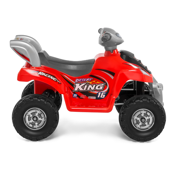
- Page 1 INSTRUCTION MANUAL Kids Ride-On ATV SKY1788 + SKY1789 Ver. 2...
-
Page 2: Battery Warnings
SAFETY Please retain these instructions for future reference. This vehicle must be assembled by an adult who has read and understood the instructions in this manual. Keep the packaging and bags away from children and dispose of all packaging before use. Always use common sense and safe practices when operating this vehicle. -
Page 3: User Warnings
USER WARNINGS • Never leave a child unattended. • Always sit in the seat when using this vehicle. • Keep your hands, hair, and clothes away from moving parts. • Always wear shoes when operating this vehicle. • Only one rider is allowed on the vehicle at a time. •... -
Page 4: Tools Required
TOOLS REQUIRED PHILLIPS SMALL WRENCH TOOL SCREWDRIVER WRENCH (PROVIDED) 66 LBS 1 PERSON APPROXIMATELY ASSEMBLY 25 MIN. CAPACITY ASSEMBLY HARDWARE NUT 5MM HANDLEBAR SCREW FRONT AXLE FRAME SMALL SCREW LARGE SCREW 5X33 BOLT 5X13 3.5X12 4X15 1 PCS 2 PC 3 PC 6 PC 2 PC... -
Page 5: Product Assembly
PRODUCT ASSEMBLY Flip the vehicle over and lay it on a level surface. Insert the part C front wheel frame into the designated slots and secure it with six part 4 large screws. Cut the zip ties securing the axles and flip them outwards. Insert the center of the part B bumper into the front wheel frame, and then attach the bumper with three part 3 small screws. - Page 6 PRODUCT ASSEMBLY Insert the part E steering column through the front wheel frame and vehicle body. Remove the nut and bolt on the end of the steering column. Slide the part D front axle frame onto the steering column and secure it to the front wheel frame with two part 2 bolts and two part 5 nuts. Replace the nut and bolt on the steering column.
- Page 7 PRODUCT ASSEMBLY Remove the nuts on the left/right front wheel axles. Slide a part F wheel and part 6 washer onto the front wheel axle, then replace the nut to secure the wheel. Repeat on the other side. Note: Use the wrench tool and screwdriver to tighten the nuts.
- Page 8 PRODUCT ASSEMBLY Flip the vehicle over. Slide the part A handlebars onto the steering column and route the connector from the handlebars into the vehicle body. Secure the handlebars to the steering column with the part 1 handle- bar screw. Underneath the vehicle, join the connector from the handlebars to the connecter leading from the Within the seat, join the red wire to the red terminal...
- Page 9 PRODUCT ASSEMBLY Place the part G seat in position and secure it with the part 7 seat screw. Snap the part H spoiler onto the rear of the vehicle. Pg. 9...
-
Page 10: Care And Maintenance
CHARGING INSTRUCTIONS & WARNINGS • Charging socket is located on the back of the vehicle on the right side. Insert one end of the part J charger into the charging socket and plug the other end into a wall outlet. •... -
Page 11: Troubleshooting
TROUBLESHOOTING Problem Reason Solution Fully charge the battery Low battery Electrical protection Stop use for several minutes and restart Vehicle does not move Switch not in the correct Completely press in switches position Battery connectors Plug in battery connectors disconnected Battery connectors Plug in battery connectors disconnected... -
Page 12: Product Warranty Information
ASSEMBLY IS COMPLETE! PRODUCT WARRANTY INFORMATION All items can be returned for any reason within 60 days of the receipt and will receive a full refund as long as the item is returned in its original product packaging and all accessories from its original shipment are included. All returned items will receive a full refund back to the original payment method.
Need help?
Do you have a question about the SKY1788 and is the answer not in the manual?
Questions and answers