
Related Manuals for Triplett Fox & Hound

Summary of Contents for Triplett Fox & Hound
- Page 1 TRIPLETT Instruction Manual GlobalTestSupply www. .com uality Products Online at: sales@GlobalTestSupp...
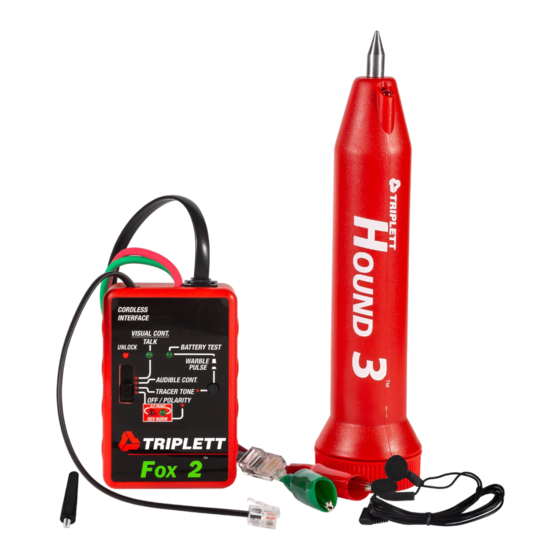
- Page 2 (loop mA and line polarity), provides a visual and audible continuity test, and incorporates Triplett’s True Trace and TripLatch tests. The HOUND 3 is a battery operated handheld lightweight Probe, with a thumbwheel Sensitivity control and Signal Strength indicator LED.
- Page 3 When used together, the FOX 2 and HOUND 3 aids in identi- fying, locating, and tracing wires, cables, and other conduc- tors. When the FOX 2 is used to apply a “tone” to a wire, the HOUND 3 can usually locate the wire inside of, or behind electrically non-conductive surfaces (plastic, wood, drywall, etc), up to 12 inches away.
- Page 4 • High Output Tracer Tone • Generates 2 of 6 user selectable Tracer Tones • Internal User Selectable Settings - HI/LO Pitch Shift, Warble/Continuous Tracer Tone, On/Off Audio Pilot Tone, On/Off Cadence Shift • Tone/Battery LED - indicates that Tracer Tone is on and battery is OK •...
-
Page 5: Safety Warnings And Cautions
• Includes New Conductive Plastic Duck-Bill Tip for Safer, Easier Penetration in cable bundles - Metal tip also included • Easy Access Battery Door • Adjustable volume / sensitivity control • LED gets brighter as the signal gets stronger - LED indication even works when Earphones are used! •... - Page 6 The FOX 2’s 120VAC warning beeper will not sound if the battery is dead. Do not rely on the beeper to indicate the presence of dangerous voltages. The 120VAC protection circuit in the FOX 2 uses a light bulb, whose glow can sometimes, but not always, be seen thru the FOX 2’s case.
- Page 7 Potentials applied to any connection of the FOX 2 may ap- pear on other FOX 2 connections. For example, a potential applied to the alligator clips may appear on the RJ-45 jack and the Wireless Interface plug. This could pose a shock hazard to the user, if for example, a LAN cable with 120VAC on it is connected to the FOX 2.
- Page 8 4.11 Use caution when working with telephone lines. They can support dangerous voltages. 50VDC is often present, and 100VAC may be present during ringing. Additionally, tele- phone lines may support dangerous levels of common mode voltages. In some circumstances, user injury may result. 4.12 Use caution when working with any long unconnected wire or cable.
- Page 9 5: Specifications 5.1: FOX 2 Specifications 5.1.1: Telephone Line Polarity Test: Indication: Red and Green LEDs light for Normal and Reversed polarity Load: Approx. 13mA at 50VDC (usually less than off-hook recognition current) Protection: Tolerates momentary 120VAC Line Cross without damage. 5.1.2: Telephone Line Ringer and Visual Ring Indication: Indication: Red and Green LEDs light simultaneously, Beeper sounds...
- Page 10 True Trace Response Time: 500 milliseconds max at 100 Ohms or less 1 second max at 10K Ohms True Trace Threshold: 10K Ohms or less Internal Settings: Warble or Continuous Tracer Tone Hi or Lo Pitch Tracer Tone Pilot Tone On or Off True Trace On or Off Protection: Tolerates momentary 120VAC Line Cross without damage.
- Page 11 5.1.6: Audible Continuity: Beeper sounds when continuity is established Threshold: Typically 500 to 1000 Ohms with new 9v battery Open Circuit Voltage: 10v max. Test Current: 60mA max 5.1.7: Visual Continuity: LED lights when continuity is established Threshold: Typically 2K Ohms with new 9v battery Open Circuit Voltage: 10v max.
- Page 12 5.1.10: Power: Battery: Standard 9v Alkaline Battery Battery Life: Approx 100 hours continuous in Tone Generator mode Telephone Line Powered Operation: Tone Generator operates without 9v battery installed. Operates from standard telephone line (46 to 53v, 400 to 1800 Ohms) in normal or reverse polarity.
- Page 13 5.2: HOUND 3 Specifications 5.2.1: Amplifier High impedance bootstrapped FET input for high gain and sensitivity. Incorporates a bandpass filter to improve sensi- tivity to FOX signals while suppressing 60Hz. 5.2.2: Sensitivity Detects FOX’s tone up to 12 inches away. 5.2.3: Speaker 1-1/2"...
- Page 14 5.2.6: Signal Strength Indicator Bright red LED signal strength indicator maintains sensitiv- ity, even when the earphone is used. 5.2.7: Power A standard 9 volt alkaline battery (NEDA 1604A, Eveready 522) provides power for all circuitry. The battery is acces- sible by removing a convenient snap-on door (no tools required).
-
Page 15: Control Locations
6: Fox 2 and Hound 3 Control Locations (See Figures 1 and 2) CORDLESS INTERFACE VISUAL CONT. TALK BATTERY TEST UNLOCK WARBLE PULSE AUDIBLE CONT. TRACER TONE OFF / POLARITY AC / RING REV NORM A Cordless Interface B Continuity / Talk LED C Unlock Button D Function Switch Polarity LEDs... -
Page 16: Control Locations
Conductive Plastic Duckbill Tip Metal Conical Tip LED Lights Signal Strength Indicator Power Button Sensitivity Control Earphone Jack Battery Connector Battery Strap Battery Cover Battery (not included) Speaker Cover Figure 2 Hound 3 Control Locations GlobalTestSupply www. .com uality Products Online at: sales@GlobalTestSupp... -
Page 17: Getting Started
7: Getting Started 7.1: The FOX 2 7.1.1: The Power Latch feature of the Function switch prevents accidental turn-on of the FOX 2. To apply power to the FOX 2, press the Unlock button down while sliding the Function switch from the OFF / POLARITY position to one of the other switch positions. -
Page 18: Notes
sible for the battery to test OK, and for the TRACER TONE mode to work, but for the AUDIBLE CONT mode not to work. This happens when the battery is weak, with enough power to operate the TRACER TONER mode, but not enough power to operate the AUDIBLE CONT mode. - Page 19 Lights will be bright, and the HOUND 3’s Speaker (LL) will produce a loud, strong, signal from the FOX 2. As the bat- tery is drained, the signal from the FOX 2 will not sound as loud in the HOUND 3’s Speaker. When the Lights begin to dim, the battery should be replaced.
- Page 20 The HOUND 3’s Sensitivity Control is usually set to maxi- mum when tracing wires through walls and ceilings, and is set to a lower setting when in close proximity to the signal carrying wires. In situations where there is a lot of acoustic noise, observing the brightness of the LED, or using ear- phones, may prove more useful than attempting to hear the signal from the speaker.
- Page 21 The conductive plastic duckbill tip will not short out most electrical circuits. The conductivity of the probe is very low compared to the metal tip. Additionally, the slender duckbill shape allows the tip to be inserted into wire bundles while searching for the target wire.
- Page 22 junction boxes, metal conduit, etc.), the effectiveness of the HOUND 3 is impaired. In multi-wire cables, grounded wires, or wires connected to low impedance circuits, adjacent to the target wire can act as shields, reducing the HOUND 3’s ability to sense properly. Spreading the wires apart will re- duce the shielding effect and allow the HOUND 3 to work better.
- Page 23 per separator can get wet from exposure to the weather. The exterior surface of the Romex can be dry, but because the internal paper separator is wet, it shields the tracer signal. Extremely high humidity will damp (collapse) the electro- static field, reducing the effectiveness of the HOUND 3 in finding the FOX 2 signal.
- Page 24 Switch (D) sets the basic operating mode. The 4 positions each have several testing functions associated with them. The follow text describes these test features in detail. The red and green LEDs (E) provide indication of telephone line polarity. An adapter cable (F) is provided to allow the RJ-45 jack (G) on the FOX 2 to be connected to an RJ-11 jack.
- Page 25 To test polarity using the clip leads, connect the red clip to the Ring wire, and the green lead to the Tip wire. If the line is live and the polarity is correct, the green NORM (Normal) LED will light. If the polarity is backwards, the red REV (Re- versed) LED will light.
- Page 26 8.1.3: Continuity Testing: The FOX 2 has both audible and visual continuity tests. Usu- ally, continuity tests are performed using the red and green clip leads . . . although it will also work through the RJ-45 / RJ-11 Adaptor cable. For the greatest degree of safety, use the clip leads.
- Page 27 Set the switch on the FOX 2 to VISUAL CONT / TALK, and connect the talksets as shown in Figure 3. CORDLESS INTERFACE VISUAL CONT. TALK BATTERY TEST UNLOCK WARBLE PULSE AUDIBLE CONT. TRACER TONE OFF / POLARITY AC / RING REV NORM Figure 3 Connecting Talksets to FOX 2...
- Page 28 a HOUND 3. In some instances, a HOUND 3 can be difficult to use to identify the target wires. The cordless handset can be a valued test tool in these cases. For example, when attempting to identify a target pair of wires in cramped quarters (like a crawl space), it can be dif- ficult to hold the HOUND 3, keeping its power button de- pressed, grab the suspect wires, and selectively short out...
- Page 29 next to the FOX 2. Test the setup by setting the FOX 2 to TRACER TONE, and turning on the cordless handset. The tracer tone should be heard clearly in the handset. Momen- tarily short the clip leads of the FOX 2 together. The cadence of the tracer tone should change.
- Page 30 8.1.6: 120VAC Warning: The FOX 2 provides an audible warning that 120VAC has been connected to the product. This is intended to provide the user with a warning that an unexpected potentially dan- gerous voltage is present. This feature works in all test modes.
- Page 31 • The FOX 2 will not trace “live” AC or DC power wires. It is protected against accidental application of 120VAC (“line cross”). • The only type of “live” circuit that the FOX 2 will trace is a telephone circuit. •...
- Page 32 crosstalk, but other wire/cables crosstalk readily. So much crosstalk can occur that the tracer tone on the adjacent wires can be almost as large as the original tone on the target wire. This can make it difficult to identify the target wire with the HOUND 3.
- Page 33 When the FOX 2 is initially set to the TRACER TONE mode, it may come on with either fast or slow cadence. 8.1.8.2: 60Hz Noise and Pulse Tone: Although the FOX 2 is not affected by 60Hz Noise, the HOUND 3 will pickup and amplify the noise.
- Page 34 LED to flash, helping differentiate the actual tone from 60Hz Noise (which causes the LED to light continuously). 8.1.9: Wire Tracing, Identification, and Open Faults: The uses of the FOX 2 Tracer Tone mode can usually be di- vided into three categories . . . tracing, identification, and locating open faults.
- Page 35 CORDLESS INTERFACE VISUAL CONT. TALK BATTERY TEST UNLOCK WARBLE PULSE AUDIBLE CONT. TRACER TONE OFF / POLARITY AC / RING REV NORM Figure 5 Floating or Line-to-Line Tracing In the grounded method (also called Line to Ground), one clip of the FOX 2 (either the red or green) is connected to earth ground or a “fake ground”, and the other clip is con- nected to the target wire.
- Page 36 nection to a true ground is not available, a large metal object can be used as a fake ground. For example, a large metal desk or a metal le cabinet can be used. When tracing wires in a car, trailer, or RV, etc. the metal frame or body can be used as a ground.
- Page 37 True Trace can be used in conjunction with the grounded method of tracing if the ground that is used at the FOX 2 location is also available at the end location of the wires. Simply short each suspect wire to the ground while listen- ing for a cadence change with the HOUND 3.
- Page 38 method works with the phone line connected or disconnected from the wires going to the telephone company. A stronger trace is usually obtained if the wires are not connected to the telephone company. If the wires are not connected to the telephone company, the grounded method can be used to trace telephone wires through a wall or ceiling.
- Page 39 other clip of the FOX 2 to one wire and then the other, while listening to the tracer tone on this clip with the HOUND 3. If the level of the tracer tone drops signi cantly when the clip is connected to one of the wires, this wire is probably OK and the other wire is open.
- Page 40 metal object (like a furnace duct) that prevents the HOUND 3 from picking up the tracer signal, or the wires may diverge from the path of the receiver. Before assuming that the open has been located, try finding the signal nearby or in an adja- cent attached wall or ceiling.
- Page 41 above), but if the hint works, the user won’t have to open the modular jack housing to gain access to the wires. 8.1.9.3: Coaxial Cable: Coaxial cable, like that used for cable TV, satellite TV, closed circuit TV, early LAN systems, etc. is often connected to other cables through splitters, combiners, or amplifiers.
- Page 42 CORDLESS INTERFACE VISUAL CONT. TALK BATTERY TEST UNLOCK WARBLE PULSE AUDIBLE CONT. TRACER TONE OFF / POLARITY AC / RING REV NORM Figure 8 RJ-45 to BNC Adaptor (PN: 2455-824) To identify the coax, if using the oating method, momen- tarily short the shield and center conductor together to ac- tive True Trace, and listen for the cadence change.
- Page 43 To identify the coax, if using the grounded method, momen- tarily short the shield to ground to active True Trace, and listen for the cadence change. If it changes, you’ve found the target coax. If no change occurs, keep searching. This will not work if a fake ground is being used.
- Page 44 or ceiling, that the wires may pass behind a metal object (like a furnace duct) that prevents the HOUND 3 from pick- ing up the tracer signal, or the coaxes may diverge from the path of the receiver. Before assuming that the open has been located, try finding the signal nearby or in an adjacent at- tached wall or ceiling.
- Page 45 to use a light bulb to activate True Trace. Simply connect a 120VAC incandescent bulb (any wattage) across the wires. If the bulb lights, the line is live. If the cadence changes, the target wire has been located. If nothing happens, keep search- ing.
- Page 46 like the previous wire. Now, slowing move the HOUND 3 from one wire to the other wire. Notice that at approximately the midpoint between the wires, the tracer tone becomes very weak. This is the “null point” . . . the place where the signal from one wire cancels the signal from the other wire.
- Page 47 how a null point occurs at the gap. This technique can be used to nd the open fairly precisely, if the spacing of the wires and the location of the open lends its to this approach. STRONG SIGNAL NULL OPEN CORDLESS INTERFACE VISUAL CONT.
- Page 48 Now, attach one of the clips and the wire attached to it to a good earth ground. See Figure 11. The HOUND 3 should pickup very little signal from the grounded wire. Move the HOUND 3 along the length of the wire and note how a strong signal is picked up on one side of the open fault, and very little signal is picked up on the other side of the fault.
- Page 49 For the most accurate simulation, lay out a serpentine pat- tern on the floor similar to that in the ceiling, and locate the open in different places, using the nulling and the grounding technique. Have an assistant position the open fault while you are out of the room, and then cover the wire with card- board, newspaper, plywood, etc.
- Page 50 any loads or any other wires, or the tracer tone will be shorted out, or it will migrate into other wires. Because wires adja- cent to the target wire will often acts as shields, and be- cause the wires in cars are often bundled together into har- nesses, it may be difficult to follow the target wire through the harness.
- Page 51 water, and the other clip to the wire to be traced. If neces- sary, attach an extension wire to the FOX 2 so that the clip will reach the “grounded” metal object. If there is no grounded metal object, simply drop the extension wire over- board into the water.
- Page 52 . . . or a special user constructed plug/jack made for this purpose. Specialized LAN testers, like the Triplett PairMaster, WireMaster XR-2, WireMaster XR-5, or LAN TDR can easily identify LAN cable faults. These faults are usually right at the RJ-45 connectors.
- Page 53 together, leaving the open faulted wire as the 8th wire. Con- nect the 7 wires to one clip of the FOX 2, and connect this clip to earth ground. Connect the open faulted wire to the other clip of the FOX 2. Trace along the path of the cable (which has already been located) with the HOUND 3, listen- ing for a sudden drop in the tone level.
- Page 54 8.1.9.10: Miscellaneous Multiwire Cables: Some general principles are important to keep in mind when locating and tracing wires and cables. Any wire with a signal on it, which runs parallel to another wire or wires tends to couple its signal to the other wires. The closer the wires are together, and the longer the parallel run, the more signal that is coupled.
- Page 55 8.1.10: Setting the FOX 2’s Options: Figure 12 shows a diagram of the locations of the internal options jumpers. Here’s what the jumpers do: Figure 12 GlobalTestSupply www. .com uality Products Online at: sales@GlobalTestSupp...
- Page 56 J1: Turns the TrueTrace feature on and off In some cases, the user may find that TrueTrace doesn’t behave as desired. TrueTrace is on when the jumper is in the DOWN position, and off when the jumper is in the UP position. J3: Sets the pitch range of the Tracer Tone With the jumper in place, the pitch is low.
- Page 57 8.2 HOUND 3 Details (refer to Figure 2) 8.2.1: Power Button The Power Button (EE) is typically pressed and held while the HOUND 3 is being used. When pressed, the Amplifier and Speaker (LL) is activated, and the LED lights (CC) are turned on.
- Page 58 8.2.3: Sensitivity Control The Sensitivity Control (FF) adjusts the loudness of the sound from the Speaker. Usually, when initially searching for the target signal, the Control is set to maximum. At this maxi- mum setting, electronic noises from electrical wiring or de- vices may be heard.
- Page 59 HOUND 3’s probe. When the plug is inserted into the jack, the HOUND 3’s speaker is turned off, and the sound can only be heard through the earphone. To use the earphone, set the HOUND 3’s Sensitivity Control to minimum, plug the earphone into jack, and press the Power button.
- Page 60 8.2.6: Conductive Plastic (AA) and Metal Probes (BB) Two probes are provided with the HOUND 3. They are easily changed by screwing and un-screwing them from the tip of the HOUND 3. The metal conical probe is rugged and durable. If working with low voltage wiring, the metal probe can provide a sig- nificant increase in signal loudness when the metal in the target wire, or a metal contact connected to the target wire,...
- Page 61 9: Notes GlobalTestSupply www. .com uality Products Online at: sales@GlobalTestSupp...
- Page 62 10: Warranty Info ONE YEAR LIMITED WARRANTY The Triplett / Jewell Instruments warrants instruments and test equip- ment manufactured by it to be free from defective material or work- manship and agrees to repair or replace such products which, under...
- Page 63 Some states (USA ONLY) do not allow the exclusion or limitation of incidental or consequential damages, so the above limitation or ex- clusion may not apply to you. No representative of Triplett / Jewell Instruments or any other person is authorized to extend the liability of Triplett Corporation in connection with the sale of its products beyond the terms hereof.
Need help?
Do you have a question about the Fox & Hound and is the answer not in the manual?
Questions and answers