Advertisement
Advertisement
Table of Contents

Related Manuals for TECSYSTEM NT935


Summary of Contents for TECSYSTEM NT935
- Page 1 INSTRUCTION MANUAL NT935 1MN0102 REV. 0 operates with ISO9001 certified quality system R. 1.6 15/03/17 ENGLISH “Translations of the original instructions”...
-
Page 2: Table Of Contents
INTRODUCTION First of all we wish to thank you for choosing to use a TECSYSTEM product and recommend you read this instruction manual carefully: You will understand the use of the equipment and therefore be able to take advantage of all its functions. - Page 3 11) TECHNICAL SPECIFICATIONS OF THE EXTENSION — ………………………………….. CABLE FOR Pt100 ………………………………….. 12) FCD FUNCTION — ………………………………….. 13) WARRANTY CONDITIONS ………………………………….. 14) TROUBLESHOOTING — ………………………………….. 15) EQUIPMENT DISPOSAL — ………………………………….. 16) USEFUL CONTACTS ………………………………….. 17) UL SPECIFICATION AND RATINGS NT935 SERIES...
-
Page 4: Safety Requirements
POWER SUPPLY The NT935 series control unit has UNIVERSAL power supply, i.e. it can be supplied at 24 to 240 Vac-Vdc, irrespectively of polarity in Vdc. Before use, ensure that the power cable is not damaged, knotted or pinched. Do not tamper with the power cable. -
Page 5: Accessories
1 RS485 terminal 3 poles pitch 3.81 (*) Code: 2PL0366 - Screws tightening torque 0.25Nm (*) only for NT935 AD version ATTENTION: always install the device using the terminals included in the pack. The use of terminals other than those included with the control unit might cause malfunctions. -
Page 6: Technical Specifications
NT935 BASIC NT935 AD TECHNICAL SPECIFICATIONS POWER SUPPLY 24-240 Vac-Vdc 24-240 Vac-Vdc Supply rated values 50/60HZ 50/60HZ 20-270 Vac-Vdc 20-270 Vac-Vdc Maximum and minimum supply values 50/60HZ 50/60HZ ● ● Vdc with reversible polarities INPUTS ● ● 4 inputs for RTD sensors, Pt100 type with 3 wires (max section 1.5mm²) ●... - Page 7 TECHNICAL SPECIFICATIONS NT935 BASIC NT935 AD ● ● Housing NORYL 94 _V0 ● ● Absorption 7,5VA ● ● Data memory 10 years minimum ● ● Digital linearity of sensor signal ● ● Self-diagnostic circuit Protection treatment of the electronic part...
-
Page 8: Front Panel
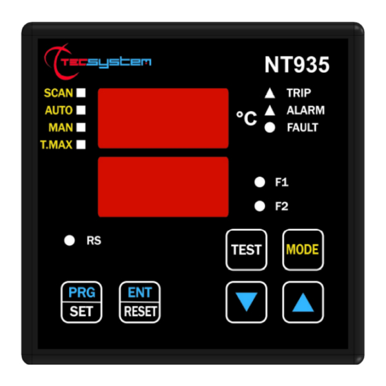
FAN 1 (yellow) LED T-max mode selection (red) LED FAN 2 (yellow) LED Man mode selection (yellow) LED Display mode selection key Auto mode selection (green) LED Fixing block Scan mode selection (yellow) LED UP key Fixing block DOWN key NT935 ASERIES... -
Page 9: Display
The first display is dedicated to temperatures The second display to the monitored channel. When switching the device ON or following a reset, the display shows the NT935 control unit model : BAS (no option) or AD, VER "00" (firmware version) and temperature range. -
Page 10: Mounting
Drill a 92 x 92 mm hole in the panel sheet. 1MN0007 REV. 0 Control unit Panel hole dimensions (+0.8mm tolerance) Identification label Fix the unit securely with the blocks supplied. 1MN0008 REV. 0 Control unit Fixing screw Fixing block Crosshead screwdriver #1X100mm NT935 ASERIES... -
Page 11: Electrical Connections Nt935 Basic
ELECTRICAL CONNECTIONS NT935 BASIC Pt100 sensors (white-red-red) Relays (FAN2-FAN1-ALARM-TRIP-FAULT) Supply 24-240Vac-dc 50/60Hz. Note: relay contact image in non-alarm condition, with the exception of the FAULT relay that opens: contacts 11-12 open (NO) contacts 11-12 closed (NC) fault condition identification. Read the Alarms and Ventilation paragraph on page 13 3 and see the opening of the fault contact. - Page 12 ELECTRICAL CONNECTIONS NT935 AD Pt100 sensors (white-red-red) Relays (FAN2-FAN1-ALARM-TRIP-FAULT) Supply 24-240Vac-dc 50/60Hz. Output 4.20 mA Modbus RTU RS485 output Note: relay contact image in non-alarm condition, with the exception of the FAULT relay that opens: contacts 11-12 open (NO) contacts 11-12 closed (NC) fault condition identification. Read the Alarms and Ventilation paragraph on page 13 and see the opening of the fault contact.
-
Page 13: Power Supply
POWER SUPPLY The NT935 control unit has UNIVERSAL power supply, i.e. it can be supplied by 24 to 240 Vac-Vdc, 50/60Hz irrespectively of polarity in Vdc (terminals 40-42). This is obtained thanks to the use of a tested power supply unit, newly designed and manufactured, that frees installers from worrying about the correct Vac and Vdc supply. -
Page 14: Programming
PROGRAMMING NT935 BASIC/AD STEP PRESS EFFECT PRESS NOTES Keep the PRG key pressed until the display shows PRG Select PRG SET for entering in the programming mode or PRG 1 default value PRG 1 to restore the default programmed value. -
Page 15: Nt935
Default NO Set YES or NO The display shows FLS (FAULT) LED flashes FAULT Set YES or NO Default YES For NT935 (BAS) version jumps to step 45 Modbus address ADR <> "datum" is displayed Default 001 Set the address... -
Page 16: Programming Notes
/ electrical fault of the Pt100 sensors c) damage to the Pt100 inputs of the control unit. TECSYSTEM S.r.l. has designed its own special cable to transfer the measurement signals, CEI-compliant, with all the protection requirements provided for: model CT-ES... -
Page 17: Temperature Sensor Diagnostics
CAL message display: it appears when damage is found in the measurement circuit. The temperature values displayed might be incorrect. Return the control unit to TECSYSTEM for repairs. VOTING FUNCTION The voting function derives from the redundancy concept that consists in duplicating the components of a system to increase their reliability. -
Page 18: Cooling Fan Control
COOLING FAN CONTROL The NT935 control unit is fitted with two FAN controls (FAN1 and FAN2) and, if programmed correctly, can control the fans switching ON and OFF to cool the transformer. The FAN1 and FAN2 contacts can manage cooling the transformer and the room where it is installed. - Page 19 The NT935 AD control unit is in communication with the network only when it is in temperature reading mode, while it is inactive when in the following modes: display, programming and relay test.
- Page 20 Trip thresholds and that the Fan-on thresholds must be higher than the Fan-off thresholds. If you try to set these thresholds wrongly, the NT935 monitoring unit won’t proceed with programming and data storage; therefore in the following readings you will read the data relevant to the previous programming.
- Page 21 In the case in which all the fans are turned off (F1, F2) the test of the relay will not take place. UNACCEPTABLE DATA Some programming is unacceptable since the NT935 AD does not provide for it; these data are discarded with no EXCEPTION CODE.
- Page 22 HFN (Fan test) 0=No test 1÷200h temperature 0=No FCD increment 1÷30°/sec 0=No Voting Voting 1=YES CPU Setting See Note CPU Error See Note See Note Relays Status reference 0=hot 420 mA channel channel for 4.20 1÷4= ch1÷4 5=scan NT935 ASERIES...
- Page 23 1°C÷200°C (*) 2’compl. Ch2 temper. 1°C ÷ 240°C 2’compl. sign As (TRP) trip set point 1°C÷200°C (*) –10°C ÷ 240°C 2’compl. sign 2’compl. Ch3 temper. –48°C÷200°C (*) 0°C ÷ 240°C 2’compl. sign 2’compl. Ch3 max temperat. 0°C÷200°C (*) NT935 SERIES...
- Page 24 2’compl. Ch4 max temperat. 0°C÷200°C (*) 2’compl. Ch4 temper. 1°C ÷ 240°C 2’compl. sign alarm set point 1°C÷200°C (*) 2’compl. Ch4 temper. 1°C ÷ 240°C 2’compl. sign trip set point 1°C÷200°C (*) (*) for version –40°C ÷ +200°C NT935 ASERIES...
- Page 25 Data HI Data LO Note 1 Note 2 (10) read/write Ch1 story Ch1 status See Note CHx Ch2 story Ch2 status See Note CHx Ch3 story Ch3 status See Note CHx Ch4 story Ch4 status See Note CHx NT935 SERIES...
- Page 26 BIT 4 BIT 3 BIT 2 BIT 1 BIT 0 PT ERROR FCD Fault CPU SETTING BIT 7 BIT 6 BIT 5 BIT 4 BIT 3 BIT 2 BIT 1 BIT 0 Failsafe Failsafe fault Failsafe trip alarm NT935 ASERIES...
- Page 27 FAIL SAFE FUNCTION The NT935 has n.o selection (contact open ) / n.c (normally closed contact) for ALARM, TRIP and FAULT relays, programming steps 30 to 35 page 15. The selection of the setting YES/NO introduces functions Fail Safe and No Fail Safe.
- Page 28 FCD function from activating during motor startup, or where the ΔT/sec. increase varies quickly. (*) The ΔT value shows the temperature range for each second. NOTE: you should not enable the FCD function with active VOTING. NT935 ASERIES...
- Page 29 Returning used electrical devices: contact TECSYSTEM or your TECSYSTEM agent for information on the correct disposal of the devices. TECSYSTEM is aware of the impact its products have on the environment and asks its customers active support in the correct and environmentally-friendly disposal of its devices.
- Page 30 5 relay Output: 10A 250Vac-res COS=1 OUTPUTS RELAYS OPTIONAL PORTS (AD) RS485 + 4.20mA Suitable for use on a flat surface of a type 1 enclosure if Back panel is provided with two short fixing screws tightening torque : 0.57Nm NT935 ASERIES...
Need help?
Do you have a question about the NT935 and is the answer not in the manual?
Questions and answers