Advertisement
Quick Links
OWNER'S GUIDE & INSTALLATION INSTRUCTIONS
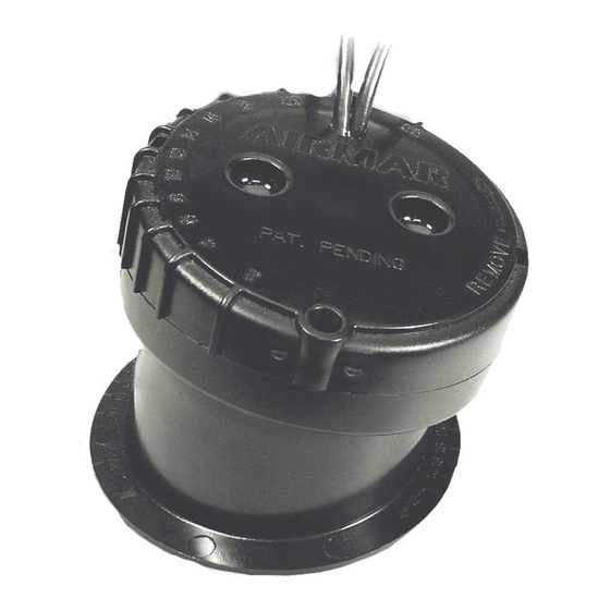
In-Hull
Adjustable-angle Depth Transducer
Models: P79, P79S Smart
CHIRP Models: P75M, P95M
Patents apply to some models. U.S. Patent No. 6,201,767; 7,369,458; 8,582,393.
EP Patent No. 1 118 074. UK Patent No. 2 414 077.
Follow the precautions below for optimal
product performance and to reduce the risk of
property damage, personal injury, and/or death.
WARNING: Always wear safety glasses, a dust mask,
and ear protection when installing.
CAUTION: CHIRP transducer—Always operate the
transducer in liquid. Operating in air will allow the
transducer to overheat resulting in failure.
CAUTION: Fiberglass hull—The hull must be SOLID
fiberglass under the transducer. The transducer will
not transmit through coring material such as foam or
balsa wood.
CAUTION: CHIRP transducer—Do not install in the
engine compartment or other hot place. The
transducer may fail if the temperature of the liquid in
the tank exceeds 60° C (140° F).
CAUTION: Never pull, carry, or hold the transducer by
the cable. This may sever internal connections.
CAUTION: Do not use an epoxy adhesive because it
is too brittle.
CAUTION: Never use solvents. Cleaner, fuel, sealant,
paint, and other products may contain solvents that can
damage plastic parts, especially the transducer's face.
IMPORTANT: Please read the instructions completely
before proceeding with the installation. These
instructions supersede any other instructions in the
instrument manual if they differ.
Applications
• For fiberglass hulls only
• Recommended for high-speed powerboats and racing sailboats
• Accommodates a deadrise angle of up to 22°
Tools & Materials
Safety glasses
Dust mask
Ear protection
Adhesive tape
Pole
Detergent (some installations)
Weak solvent (such as alcohol)
Disk sander (some installations)
Thin sealable plastic bag (some installations)
Cable ties (some installations)
Water-based lubricant (such as K-Y® jelly) (some installations)
Angle finder or digital level
Record the information found on the cable tag for future reference.
Part No._________________Date___________Frequency________kHz
Sensor
™
Carpenter's square
Pencil
Silicone sealant (such as GE® Silicone I or Silicone II)
Screwdriver
Petroleum jelly (such as Vaseline® brand)
Propylene glycol (non-toxic antifreeze/coolant) 71ml (2.4 fl. oz.)
Level
Grommet(s) (some installations)
Installation in a cored fiberglass hull (see page 4):
Mounting Location
About Fiberglass Hulls
The fiberglass hull below the transducer must be solid. Since the
hull absorbs acoustic energy, transmitting through the hull
reduces the transducer's performance. Fiberglass hulls are often
reinforced in places for added strength or to reduce weight. These
cored areas contain balsa wood or structural foam which are poor
sound conductors. Do not locate the transducer over coring.
Placement
CAUTION: Do not mount the transducer in line with or near water
intake or discharge openings or behind strakes, fittings, or hull
irregularities that will disturb the water flow.
Choose a location:
• Where the fiberglass is SOLID (no air bubbles are trapped in
• Where the hull below the transducer will be in contact with the
• Where the water flowing under the hull is smoothest with a
• Away from interference caused by power and radiation sources
• Where the transducer beam will not be blocked by the keel or
• Where the deadrise angle does not exceed 22°.
• Where there is space inside the vessel for the height of the unit,
• CHIRP transducer—Mount in a cool well-ventilated area away
Electric drill
Hole saw
Miniature disk sander (such as Dremel® rotary sander)
Repair epoxy (such as Pettit Flexpoxy 7076) or resin
Paper cup (some installations)
Stirrer (some installations)
the fiberglass resin) and where no coring, flotation material, or
dead air space is sandwiched between the inside skin and outer
skin of the hull.
water at all times.
minimum of bubbles and turbulence (especially at high speeds).
such as: the propeller(s) and shaft(s), other machinery, other
echosounders, and other cables. The lower the noise level, the
higher the echosounder gain setting that can be used.
propeller shaft(s).
tightening the locking ring, and installing the transducer.
from the engine to avoid overheating. The transducer may fail if
the temperature of the liquid in the tank exceeds 60° C (140° F).
100mm or 4"
Advertisement

Related Manuals for Airmar P79


Summary of Contents for Airmar P79
- Page 1 OWNER’S GUIDE & INSTALLATION INSTRUCTIONS In-Hull Record the information found on the cable tag for future reference. Part No._________________Date___________Frequency________kHz Adjustable-angle Depth Transducer Models: P79, P79S Smart Sensor ™ CHIRP Models: P75M, P95M Patents apply to some models. U.S. Patent No. 6,201,767; 7,369,458; 8,582,393.
- Page 2 Best location for the transducer with a cable tie. Wet the surface of the hull and press the active Copyright © 2005 - 2016 Airmar Technology Corp. face of the transducer against it through the bag (Figure 3-B). Boat Types C.For any location—If the hull surface is not smooth, grind it with a...
- Page 3 Figure 6. Joining the transducer to the locking ring Figure 7. Installing the O-ring and identifying the bosses Copyright © 2005 - 2010 Airmar Technology Corp. Copyright © 2005 - 2010 Airmar Technology Corp.
- Page 4 Obtain parts from your instrument manufacturer or marine dealer. Gemeco Tel: 803-693-0777 email: sales@gemeco.com Airmar EMEA Europe, Middle East, Africa Tel: +33.(0)2.23.52.06.48 email: sales@airmar-emea.com 35 Meadowbrook Drive, Milford, New Hampshire 03055-4613, USA • www.airmar.com Copyright © 2005 - 2017 Airmar Technology Corp. All rights reserved.
Need help?
Do you have a question about the P79 and is the answer not in the manual?
Questions and answers