Advertisement
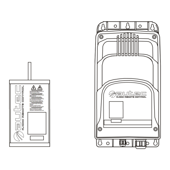
AC Receiver System
USER'S MANUAL
! !
Prima dell'accensione leggere il manuale d'uso.
Attenersi alle norme di sicurezza.
Togliere l'alimentazione in caso di apertura.
Before switching on please read the user manual.
Adhere to safety rules.
Disconnet power source before opening.
Vor Inbetriebnahme die Gebrauchsanleitung
lesen. Sicherheitsnormen beachten.
Die Speisespannung muss ausgeschaltet
werden, falls der Empfänger geöffnet wird
Avant d'allumer l'engine, lire le manuel de
l'utilisateur.
Respecter le consignes de sécurité.
Couper l'alimentation avant d'ouvrir le boîtier.
Antes de encenderlo leer el manual.
Atenerse a las normas de seguridad.
Desconectar la alimentación antes de abrir.
Advertisement

Summary of Contents for Autech Technology R202
- Page 1 AC Receiver System USER’S MANUAL Prima dell'accensione leggere il manuale d’uso. Attenersi alle norme di sicurezza. Togliere l’alimentazione in caso di apertura. Before switching on please read the user manual. Adhere to safety rules. Disconnet power source before opening. Vor Inbetriebnahme die Gebrauchsanleitung lesen.
- Page 2 Follow the indications and warnings given by the machine producer regarding the machine controlled by the radio remote control. The information contained in this manual considers a representative configuration of the radio remote control: please find radio remote control real configuration in the technical data sheet (attached to the manual).
-
Page 3: Table Of Contents
LIE&LAA0 INDEX & CONVENTIONS INDEX Page Index & Conventions Introduction Receiving units Warnings for installation Warnings for maintenance Light signals Programming Receiving unit diagnostic CONVENTIONS In this manual, all important information is indicated using the following symbols and conventions: abcd. . . WARNINGS abcd. -
Page 4: Introduction
LIE&LAA0 INTRODUCTION Industrial radio remote controls are used to command machines from a distance. Each industrial radio remote control is made up of a portable transmitting unit, from which the user can remotely control the Receiving machine, and a receiving unit installed on board the unit machine itself. - Page 5 LIE&LAA0 Autec cannot be held responsible if the radio remote control is installed on applications that are different from those permitted PERMITTED USES Material lifting machines (construction cranes, industrial bridge cranes, machines for moving material in general, . . . ) FORBIDDEN USES Machines installed in areas where equipment with explosion-proof characteristics are being used.
-
Page 6: Technical Data
LIE&LAA0 INSTRUCTIONS FOR DOCUMENT MANAGEMENT The following minimum documentation is supplied with each radio remote control: - transmitting unit manual - receiving unit manual - battery charger manual - a guarantee certificate - the radio remote control technical data sheet. Make sure that the following documents have been supplied: if they are not, request them from Autec. -
Page 7: Receiving Units
LIE&LAA0 RECEIVING UNITS The receiving unit Type R202 and Type R302 can be used with the following transmitting unit: - SERIES LIGHT - SERIES MODULAR These receiving units are equipped with a safety function called SAFETY that protects the “radio remote control + machine” system, when it is in neutral (rest position), from involuntary movements caused by possible radio remote control faults. - Page 8 - E16B22AC for configurations of up to 22 commands (plus extension interface card) E16B16AC E16B22AC F1 STOP circuit protection fuse SAFETY circuit protection fuse POWER SUPPLY protection fuse Receiving unit Type R202 TECHNICAL DATA Power supply 24/48/55/110 Vac ±20% 60 Hz (15VA) Antenna integrated or dedicated Max switching capacity of STOP contacts...
- Page 9 LIE&LAA0 RECEIVING UNIT TYPE R302 cable holder (opt. plug) POWER light identification plate ENABLE light Drilling template data technical plate antenna A=106 mm B=213,5 mm The master board in this type of receiving unit is E16B10AC for configurations of up to 10 commands.
-
Page 10: Warnings For Installation
LIE&LAA0 WARNINGS FOR INSTALLATION Installation should only be carried out by qualified people and in accordance with installation country rules. THE INSTALLER MUST PLACE the receiving unit vertically, with the cable holder (or plug) facing down. FIX the receiving unit at least in four points, using the specific holes located in the housing. - Page 11 LIE&LAA0 WARNING: The stylus of dedicated antenna (always present in the receiving unit Type R302, optional for the receiving unit Type R202), must never come in contact with metal parts. The installer must CHECK and/or COMPLETE the "Technical Data Sheet" indicating the date of activation of the system, putting his signature and stamp.
-
Page 12: Warnings For Maintenance
LIE&LAA0 WARNINGS FOR MAINTENANCE ALWA YS ENSURE THAT THE RECEIVING UNIT HAS BEEN DISCONNECTED FROM THE POWER SOURCE BEFORE CARRYING OUT ANY MAINTENANCE WORK. All the faults should be repaired by authorised Autec personnel using original Autec spare parts only. All control and maintenance interventions carried out on the radio remote control must be verified and recorded by the person in charge of carrying out maintenance on the machine. - Page 13 LIE&LAA0 ROUTINE MAINTENANCE The following instructions allow to maintain the radio remote control in a perfect condition, guaranteeing it to function safely and correctly for a long period. Special applications may need more specific routine maintenance interventions to be carried out at different periods.
- Page 14 LIE&LAA0 SPECIAL MAINTENANCE Any fault should be repaired by authorised Autec personnel (contact Service), using original Autec spare parts only. AUTHORIZED SERVICE CENTER When it is necessary to carry out special maintenance (radio remote control repair and replacement of damaged or faulty parts), do not contact anyone other than our Authorized Service Center.
-
Page 15: Light Signals
LIE&LAA0 LIGHT SIGNALS On each receiving unit there are: a POWER lamp indicates the presence of power supply in the receiving unit an ENABLE lamp which indicates radio link on between the transmitting unit and receiving unit a LED for each relay on the master board, which indicates the activation of that relay... -
Page 16: Programming
LIE&LAA0 PROGRAMMING The dip switches must be programmed when the receiving unit is not powered and can be done only by authorised personnel. The incorrect closure of the receiving unit can compromise seal between the casings and thereby the protection grade from dust and water. - Page 17 LIE&LAA0 DIP SWITCHES ON MASTER BOARDS There are a number of dip switches on the E16B16AC and E16B22AC master boards for programming various functions of the radio remote control, as explained in the following tables: DIP SWITCHES ON E16B16AC MASTER BOARD POS.
-
Page 18: Receiving Unit Diagnostic
LIE&LAA0 RECEIVING UNIT DIAGNOSTIC If the “machine+radio remote control” system does not start, check if the problem is caused by the radio remote control or the machine. Before carrying out any verifications, check the functioning of the machine with the cable control panel: if it does not switch on, the problem lies with the machine itself. - Page 19 Appendix: FREQUENCY TABLE E16SRXUS1 DIP SWITCH DIP SWITCH 902.150 OFF OFF OFF 915.350 OFF OFF OFF 903.050 916.250 OFF OFF OFF OFF 903.850 917.050 OFF OFF OFF OFF 904.650 917.850 OFF OFF OFF OFF OFF 905.525 OFF OFF 918.675 OFF OFF 919.525 906.325 907.175...
- Page 20 Tel : ++39 - 0444/901000 r.a. Via Pomaroli, 65 email: info@autec.it Fax: ++39 - 0444/901011 http://www.autec.it 36030 Caldogno (VI) ITALY...
Need help?
Do you have a question about the R202 and is the answer not in the manual?
Questions and answers