Table of Contents
Advertisement
Advertisement
Table of Contents

Related Manuals for Redarc BMS1230S2


Summary of Contents for Redarc BMS1230S2
- Page 1 MANAGER Battery Management System BMS1230S2...
-
Page 2: Warnings And Safety Instructions
REDARC for repair. Incorrect handling or reassembly may result in a risk of electric shock or fi re and may void the unit warranty. Use of an attachment not recommended or sold by REDARC may result in a risk of fi re, electric shock, or injury to persons. - Page 3 WARNINGS & SAFETY INSTRUCTIONS When using the Battery Charger to charge a Lithium Iron Phosphate battery, only batteries that feature an inbuilt battery management system featuring inbuilt under and over voltage protection and cell balancing are suitable. NEVER smoke or allow a spark or fl ame in vicinity of battery. This may cause the battery to explode. 10.
-
Page 4: Table Of Contents
CONTENTS Table of Contents Page Warnings and Safety Instructions Contents Features and Benefi ts 1 Introduction 1. General Description 2. The Remote Monitor 3. The Kit Includes 4. Specifi cations 5. Multi-stage Charging Process 6. Maximum Charging Current Setting 7. Green Power Priority 2 INSTALLATION Guide 1. -
Page 5: Features And Benefi Ts
It is manufactured with high- quality components to ISO9001 quality and ISO14001 environmental standards and backed with REDARC’s quality service and two-year warranty. 4. The Manager30 charging algorithm uses solar whenever possible making the unit more energy effi... -
Page 6: Introduction
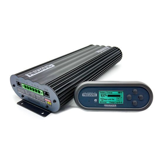
INTRODUCTION General Description The Manager30 is designed to offer a complete solution to battery charging and maintenance needs for recreational automotive applications. The Manager30 incorporates AC, DC and Solar inputs to achieve the best charge to a house battery. The Remote Monitor The Manager30 comes with a Remote Monitor designed to give you house battery information and charge status along with critical system information while charging is in progress. -
Page 7: Specifi Cations
INTRODUCTION Specifi cations Electrical Specifi cations Inputs AC Input Input Voltage Range (nominal) 220-240VAC 50Hz Power Rating 520W Effi ciency 80% - 90% Connection IEC Mains Plug DC Input Input Voltage Range 9 - 32V Turn ON/OFF Threshold 12V (24V) 13.2V/12.7V (26.4V/25.4V) Power Rating 520W... - Page 8 INTRODUCTION Figure 1.4.1 - Main Unit Dimensions Figure 1.4.2 - Remote Monitor Dimensions...
-
Page 9: Multi-Stage Charging Process
INTRODUCTION Multi-stage Charging Process The Manager30 incorporates two different multi-stage charging profi les – Touring (3-stage) and Storage (8-stage) – which can be selected in the Battery Mode menu on the Remote Monitor. Touring Mode Touring mode is designed for use when ‘on the road’. Touring mode offers a 3-stage charging profi... - Page 10 INTRODUCTION Storage Mode Storage mode is designed to charge the house battery to its optimal level and maintain that level while your caravan is in storage. This mode requires all loads to be switched off or disconnected from the house battery before charging. It uses a 8-stage* charging profi...
-
Page 11: Maximum Charging Current Setting
INTRODUCTION IMPORTANT When The Manager30 is set to ‘Storage’ mode and no valid charging sources are connected, it will enter a ‘Sleep’ mode 30 seconds after the last user interaction. The sleep mode is designed to limit the amount of current drawn from the output battery by the system whilst in Storage mode and does this by switching the screen and all non-essential functions off. -
Page 12: Installation Guide
INSTALLATION GUIDE System Layout Remote Solar Panels Monitor (Not Supplied) Battery Vehicle Sensor To Loads Battery (Not Supplied) (Not Supplied) DC - DC Power Source House Battery (Not Supplied) BMS1230 240VAC Mains Power Figure 2.1.1 - System Layout Mounting Instructions This section describes how to mount the three major components of The Manager30: the Main Unit, the Remote Monitor and the Battery Sensor. -
Page 13: Mounting The Main Unit
REDARC recommends that the Main Unit be mounted to optimise airfl ow past the heatsink. Mounting the unit horizontally (see Figure 2.2.1.1) is recommended and mounting vertically (see Figure 2.2.1.2) is still acceptable. -
Page 14: Mounting The Remote Monitor
INSTALLATION GUIDE 2.2.2 Mounting the Remote Monitor The Remote Monitor should be mounted inside the caravan or RV using the template provided inside the box. It is acceptable however to mount the Remote Monitor in any convenient location, as long as it is protected from harsh environments. -
Page 15: Wall Mount
INSTALLATION GUIDE Wall Mount Use the template provided (Page 36) Attach the Back Plate to the wall to mark the position and drill and cut using 4 suitably sized countersunk the mounting holes into the wall. screws. Feed the Remote Monitor cable Clip the Inner Assembly into the through the hole and connect it to Back Plate. - Page 16 INSTALLATION GUIDE Removing the Remote Monitor The locking tabs on the back of the The locking tabs can be accessed Inner Assembly need to be unclipped through holes on the top of the from the Back Plate. backing plate when installed. Insert a fl...
-
Page 17: Mounting The Battery Sensor
The length of cables on the Battery Sensor to connect to the Main Unit and the House Battery will dictate the allowable mounting distance from the battery however REDARC recommend mounting the Battery Sensor as close to the Main Unit as possible. - Page 18 INSTALLATION GUIDE 2.3.1 Input Wire Diameter Selection REDARC recommends the installer use cabling and connections between 8B&S and 6B&S automotive. REDARC recommends that the input wire be of the size outlined in Table 2.3.1. Distance from input vehicle Recommended Cross...
-
Page 19: The Manager30 Wiring Connections
INSTALLATION GUIDE The Manager30 Wiring Connections REDARC recommends that this unit be installed by a suitably qualifi ed person. The AC power connection must be connected to an earthed socket outlet. Do not use The Manager30 AC input if the cord is damaged. Use of a non-genuine or damaged AC input cord may result in a risk of fi... -
Page 20: Connecting The Battery Sensor
INSTALLATION GUIDE 2.4.3 Connecting the Battery Sensor Wire the Battery Sensor as shown in fi gure 2.4.1.1 ensuring that the “BNEG” stud connects to the House Battery negative terminal and the “GND” stud connects to the vehicle common ground point. Connect the CANBus Connection cable, the cable with the RJ12 connector, to the CANBus network via the T-Piece supplied (see fi... - Page 21 INSTALLATION GUIDE...
-
Page 22: Batteries
INSTALLATION GUIDE Batteries Working in the vicinity of a Lead-Acid battery is dangerous. Batteries generate explosive gases during normal operation. For this reason, it is of utmost importance that you follow the instructions each time you use the charger. When charging a battery, make sure the settings at the Battery Setup menu on the Remote Monitor are correct for the type of battery under charge. -
Page 23: Mppt Solar Regulator
INSTALLATION GUIDE MPPT Solar Regulator The Manager30 is designed for use with 12V solar panels. A minimum input voltage of 17.5V is required to start charging from a solar source. Once charging has started, the operating voltage range of the solar input can go as low as 9V and as high as 32V;... -
Page 24: User Guide
USER GUIDE Remote Monitor The Remote Monitor is designed to give you control of how the battery is being charged, as well as up-to-date house battery and charge information at any time during the charging process. You can check battery charge status, estimated charge time and State of Charge (SOC) per hour over a day and per day over a month. -
Page 25: Initial Setup
USER GUIDE Initial Setup When The Manager30 is fi rst switched on the unit will prompt the user to enter a number of settings. It is important to enter these settings accurately as they directly affect the operation and performance of The Manager30. Set the Language: The fi... -
Page 26: User Menu
USER GUIDE User Menu The Manager30 features a real time clock (time and date) function which needs to be setup when the power is fi rst connected. Set the Time & Date Charging Status Screen Battery Charge Screen The Manager30 monitors current in and out of the house battery, keeping track of the charge remaining. - Page 27 USER GUIDE The Input Status screen displays a summary of the inputs to the system. The Solar input is the priority, providing as much usable input power as possible. If another source is present and the Solar input is not providing maximum (30A) input, the other source will attempt to make up the remaining allowable input power.
-
Page 28: Settings Menu
USER GUIDE Settings Menu To access the Settings menu both the Up and Down buttons must be held for 2 seconds. This allows you to modify your Battery Setup, Remote Settings and some Advanced Settings, as well as providing a restore Factory Settings option and an About screen. - Page 29 USER GUIDE The Remote Settings menu allows modifi cation of the settings listed below. Edit Selected Setting Cycle through Settings Remote Settings Screen Cycle through Settings Each setting can be adjusted using the ‘Up’ and ‘Down’ controls. Confi rm Setting Adjustment Adjust Setting (Up) Cancel Setting Adjustment Adjust Setting (Down)
- Page 30 USER GUIDE The MaxCharge Current setting refers to the amount of current permitted by The Manager30 to charge the battery, up to a maximum of 30 Amps. Set Charging Current Screen R-Bus Diagnostics Screen Advanced Settings Screen Low SOC Alarm Screen If the Charging Current setting is set lower than 30 Amps the excess current will be used to supply the loads running from the battery under charge.
- Page 31 USER GUIDE The Load Disconnect setting will output a GROUND relay trigger signal based on a user set SOC or voltage level. Disconnect Trigger Screen Low Voltage Alarm Screen Advanced Settings Screen Set DC Input Trigger Screen The Disconnect Trigger setting can be set to Disconnect (Loads OFF), Connect (Loads ON) or to operate from either SOC or Voltage level triggers.
-
Page 32: Fault Screens
Change Setting Cancel Setting Change Setting This screen is used by REDARC to identify problems with a The Manager30 setup and does not need to be accessed unless requested by REDARC Technicians. Start Process/ More Info Set DC Input Trigger Screen... -
Page 33: Troubleshooting
The listing on the following page (33) outlines the probable cause and recommended action to take when faults occur with The Manager30 system. If after attempting to rectify the situation, a fault still occurs, please contact REDARC for further diagnosis. Contact Details: REDARC Electronics (08) 8322 4848 power@redarc.com.au... - Page 34 USER GUIDE Faults CHARGER FAULT MESSAGE CAUSE ACTION Charger over current fault An internal error has caused excessive Return to supplier current draw Charger over voltage fault The output voltage is too high (above Check battery is correct type (12V, 6 18V) cell) Unit over temperature fault.
-
Page 35: Factory Settings
USER GUIDE Factory Settings The Manager30 is shipped with a number of settings already programmed into the unit. These settings are set to ensure that the charger will safely charge any battery and may not refl ect the actual requirements for your battery type. It is important to review these settings and adjust as required. -
Page 36: Faqs
Q I have damaged my Power Cable and need to replace it, do I have to buy a special kind of cable. A To ensure the correct operation of The Manager30, REDARC advise that if the supply cord is damaged it must be replaced by a special cord available from the manufacturer. -
Page 37: Remote Drill Template
REMOTE DRILL TEMPLATE... - Page 38 THIS PAGE INTENTIONALLY LEFT BLANK...
-
Page 39: Two Year Warranty
Friendly, personalised, professional service and product support In the unlikely event that a technical issue arises with a Redarc product, customers are encouraged to initially contact the Redarc Technical Support Team on (08) 8322 4848 In the unlikely event that a technical issue arises with a Redarc product, customers are encouraged to initially contact the Redarc Technical Support Team on (08) 8322 4848 or or power@redarc.com.au... - Page 40 Free technical assistance! please contact REDARC Electronics 23 Brodie Road North, Lonsdale SA (08) 8322 4848 power@redarc.com.au www.redarc.com.au Copyright © 2015 REDARC Electronics Pty Ltd. All rights reserved. WARBMS1230S2 - REV3 www.redarc.com.au...
Need help?
Do you have a question about the BMS1230S2 and is the answer not in the manual?
Questions and answers