Table of Contents
Advertisement
Quick Links
Advertisement
Table of Contents

Related Manuals for Pulsar Imp+i.s.


Summary of Contents for Pulsar Imp+i.s.
- Page 1 IMP+ i. s . NSTRUCTION ANUAL...
- Page 3 ARRANTY AND IABILITY Pulsar Process Measurement Limited guarantee for a period of 2 years from the date of delivery that it will either exchange or repair any part of this product returned to Pulsar Process Measurement Limited if it is found to be defective in material or workmanship, subject to the defect not being due to unfair wear and tear, misuse, modification or alteration, accident, misapplication or negligence.
-
Page 5: Table Of Contents
Contents Chapter 1 Start Here… ............................1 About this Manual ............................1 About the IMP+ i.s. Level Monitoring System ....................2 Functional Description ..........................2 Product Specification............................4 EU Declaration of Conformity ........................5 Chapter 2 Installation............................6 Hazardous Area Installation ..........................6 Information specific to Hazardous Area Installation................ - Page 6 P605 Volume Units ..........................28 P606 Correction Factor ......................... 28 P607 Max Volume ..........................28 Display (DiSP) Menu ............................ 29 P800 Display Units ..........................29 P801 Decimal Places ..........................29 P808 Fail-safe Mode ..........................29 P809 Fail-safe Time ..........................29 mA Output (LOOP) Menu ..........................
-
Page 7: Chapter 1 Start Here
Chapter 1 Start Here… IMP+ i. s . Congratulations on your purchase of a Pulsar Level Monitoring System. This quality system has been developed over many years and represents the latest in high technology ultrasonic level measurement and control. It has been designed to give you years of trouble-free performance, and a few minutes spent reading this operating manual will ensure that your installation is as simple as possible. -
Page 8: About The Imp+ I.s. Level Monitoring System
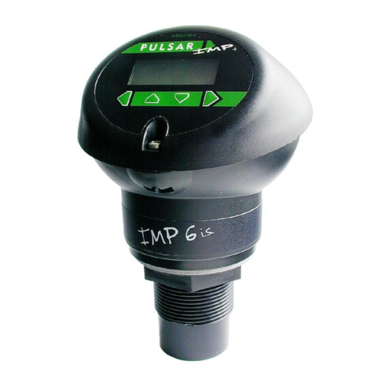
About the i.s. Level Monitoring System IMP+ Functional Description IMP+ i.s. level monitoring system is a highly developed ultrasonic level measurement system which provides non-contacting level measurement for a wide variety of applications in both liquids and solids located in hazardous areas. - Page 9 IMP+ i. s . can show level, space, distance, on the display. The current loop can be connected to a remote chart recorder or PLC that has a current input, to monitor level, space or distance, dependant on the measurement mode selected, and provides a ‘fault condition’...
-
Page 10: Product Specification
Product Specification Physical Dimensions O/A height 186mm (5.24 inches) x O/A diameter 133mm (7.32 inches) 1.5” BSP/NPT (IMP3 and 6 models) 2” Mounting BSP/NPT (IMP10) Weight Nominal 1kg 2 off cable glands 4.5 – 10mm. (torque to Cable entry 2NM) Environmental IP Rating IP67... -
Page 11: Eu Declaration Of Conformity
EU Declaration of Conformity Page 5... -
Page 12: Chapter 2 Installation
Chapter 2 Installation Hazardous Area Installation If the unit is to be used in a hazardous area, then power to the unit must pass through an approved safety barrier or approved IS PSU. Information specific to Hazardous Area Installation (Reference European ATEX Directive 2014/34/EU, Annex II, 1.0.6.) The following instructions apply to equipment covered by certificate number Sira 06ATEX2014X: The equipment may be used with flammable gases and vapours with... -
Page 13: Hazardous Area Specific Power Supply And Barrier Requirements
The certificate number has an ‘X’ suffix that indicates that the following special condition of certification applies; IMP+ i. s . In the case of due to the housing and labels being non- conductive plastic care needs to be taken with regards electrostatic charge. -
Page 14: Voltage Drop Due To I.s. Safety Zener Barrier
Terminal Connection Details IMP+ i. s IMP+ i. s . is a 2 wire (loop powered) unit, the terminal connections for is detailed below. Wiring details are also given on the terminal label under the access cover. Terminal 1 + ve: Direct Current (DC) input (12-26VDC) via barrier Terminal 2 - ve: Ground side Voltage drop due to i.s. -
Page 15: Suitable Recommended Barriers
IMP+ i . s . 2 Wire (loop powered) wiring detail Important Information IMP+ i. s . when installed in a hazardous area must be supplied through an approved safety barrier or approved i.s power supply. Suitable recommended barriers: Barrier Type Suggested Barriers Fig. - Page 16 Source means the measuring device applies a resistive load and sink means the measuring device supplies power Barriers must be fitted with reference to the manufacturers datasheets. Page...
-
Page 17: Location And Mounting Information
Location and mounting information IMP+ i. s . The compact one-piece construction of the can be mounted easily using the integral nose thread (1.5" or 2" BSP/NPT, dependent on model). When choosing a location to mount the Imp, bear in mind the following: •... - Page 18 Dimensions IMP+ i. s . The dimensions of the are as shown below. 1.5" BSP/NPT – IMP 3 & 6 i.s. 2" BSP/NPT – IMP 10 i.s. Page...
- Page 19 Outdoor and Open Vessel Installation IMP+ i. s . can be simply mounted on a bracket, suitable for the application and secured using the thread located at the top of the transducer (2"BSP/NPT). IMP+ i. s . Care should be taken to ensure that the is not installed in direct sunlight, in order to avoid errors in the measurement of ambient temperature.
- Page 20 Stand Pipe Installations IMP+ i. s . When mounting the to a standpipe care should be taken to ensure that the standpipe is of sufficient diameter with reference to its length, see the table below for details: Dia. (D) Max. Length (L) inches inches When using a standpipe, fixed to the top of a vessel, ensure that the open...
-
Page 21: Preparation For Operation
There are no user serviceable parts inside your , if you experience any problems with the unit, then please contact Pulsar Process Measurement for advice. To clean the equipment, wipe with a damp cloth. Do not use any solvents on the enclosure. -
Page 22: Chapter 3 How To Use Your Imp+ I . S . Level Monitoring System
IMP+ i . s . Chapter 3 How To Use Your Level Monitoring System Operating the Controls Display Whilst in the Run Mode, the 4-digit LCD, by default, will display the current level reading in metres, the display will also alternate between the reading and “LOE”... -
Page 23: Program Mode
Program Mode IMP+ i. s . This mode is used to set up the or change information already set, this is achieved by using the 4 push buttons located below the display. Entering a value for each of the menu options that are relevant to your application provides all the programming information. - Page 24 Assuming the passcode is the default 1997, then you should enter this. The ESC key can be used to go back to the previous digit. Finally, when you have selected all digits pressing the ENTER key again will input the selected pass code IMP+ i.
-
Page 25: Parameter Defaults
Parameter Defaults Factory Defaults Factory Defaults IMP+ i. s . When first installing the , or subsequently moving or using the unit on a new application, before proceeding to program the unit for its intended application it is recommended that you ensure that all parameters are at their default values by completing a Factory Defaults P930, as described in Chapter 5 Parameter Guide. -
Page 26: Chapter 4 Getting Results With Your Imp+ I . S
IMP+ i . s . Chapter 4 Getting Results With Your This chapter will explain how to undertake the various functions of your IMP+ i. s . . Where specific parameters are used, consult Parameter Guide in Chapter 5. Setting up Your Application Empty Distance Empty Distance (P105) is the distance from the face of the transducer to the material at the bottom of the vessel. -
Page 27: Setting Security Passcodes
By default, the 4-20 mA will represent the empty level (4mA) and 100% of the operational span (20mA), but you may wish to only represent a section of the operational span. For example, the application may have an operational span of 6 metres, but you may only wish to represent empty level to 5 metres. -
Page 28: Changing The Passcode
Changing the Passcode You can set the passcode to any number from 0000 to 9999. To do this, enter Program Mode and go to SyS1 (System) menu. Select P922 which is the Passcode parameter which can be changed as required. Resetting Factory Defaults If you need to restore parameters to their original factory settings, then enter Program Mode go to the SyS1 (System) menu and ENTER. -
Page 29: Chapter 5 Parameter Guide
Chapter 5 Parameter Guide IMP+ i. s . This chapter describes all the parameters in your Parameter Listing IMP+ i. s . This section describes all the parameters contained within the Application (APP) Menu P100 Mode of Operation This parameter sets the mode of operation, when in run mode, and can be set to one of the following: Option Description... -
Page 30: P106 Span
P106 Span This parameter should be set to the maximum distance from the Empty Level (P105) to the maximum material level. It is automatically set to be equal to the Empty Level (P105) less the Near Blanking distance (P107), when you set the empty level. Default IMP 3 = 2.80m (9.19 feet), IMP 6 = 5.70m (18.70 feet) and IMP 10 = 9.70m (31.82). -
Page 31: Volume (Uol) Menu
Volume (UoL) Menu P600 Vessel Shape This parameter determines which vessel shape is used when utilising “Volume Conversion”. The choices are as shown in the table below, along with the dimensions that are required to be entered (P601-P603). Dimensions Vessel Shape P600 Value Required P600=0 Cylindrical... - Page 32 Dimensions Vessel Shape P600 Value Required P600=6 Cylindrical Cylinder diameter and height of Flat sloped base bottom P600=7 Rectangular Width and Breadth Flat sloped base of rectangular section and height of bottom P600=8 Horizontal Cylinder diameter cylinder with flat ends and tank length P600=9 Horizontal Cylinder diameter,...
-
Page 33: P601-P603 Vessel Dimensions
P601-P603 Vessel Dimensions These three parameters are used to enter the dimension required to calculate the volume. The dimensions required are as shown below. Vessel Shape P601 P602 P603 P600=0 Cylindrical Cylinder Flat base Diameter P600=1 Rectangular Width of Breadth of Flat base rectangle rectangle... -
Page 34: P605 Volume Units
P605 Volume Units This parameter determines the units that will be used in calculating volume conversion. It is used in conjunction with P607 (maximum volume), please note that there is no provision for the volume unit’s descriptor to be shown on the display. -
Page 35: Display (Disp) Menu
Display (DiSP) Menu P800 Display Units This parameter determines whether the reading displayed is in Measurement Units (P104), or as a percentage of span. Option Description 1 = Measured (Default) Display is in Measurement Units (P104) 2 = Percentage Display is in percentage of span. P801 Decimal Places This parameter determines the number of decimal places on the reading during run mode. -
Page 36: Ma Output (Loop) Menu
mA Output (LOOP) Menu P834 mA Low Level This parameter sets, in Measurement Units (P104), the value of ‘level’, ‘space’ or ‘distance’, depending on the selected Mode of Operation (P100), at which 4mA will occur. P835 mA High Level This parameter sets, in Measurement Units (P104), the value of ‘level’, ‘space’... -
Page 37: Compensation (Cop) Menu
Compensation (CoP) Menu P851 Measurement Offset The value of this parameter is added to the measured distance, in Measurement Units (P104). This Offset will be added to the level, as derived from the transducer, and will affect everything including the reading on the display and the mA output. -
Page 38: P645 Vapour Temperature Compensation
The table below gives details of the velocity of sound in various gaseous atmospheres In all cases the velocity indicated is that in a 100% gaseous atmosphere at 0 C. In atmospheres less than 100% it may be necessary to check the level indicated at near empty and near full and compare with the actual level, several times, then adjust the Sound Velocity accordingly to obtain an accurately displayed reading. -
Page 39: P871 Empty Damping
Default = 10.000 metres/minute (32.81 feet/minute) System (SyS1) Menu The following three parameters do not affect how the unit performs, but details, contained in them, may be required, by Pulsar, when making technical enquiries. P921 Enable Code Enables the passcode (P922), which means the passcode must be entered to go into program mode. -
Page 40: Test (Test) Menu
Test (tESt) Menu P991 Hard Test When this parameter is selected, the unit will test the following in turn. • Display. All the segments on the LCD are lit up, so you can see if they all work. Press the ENTER button, to end the test. •... -
Page 41: Chapter 6 Troubleshooting
Chapter 6 Troubleshooting This section describes many common symptoms, with suggestions as to what to do. Symptom What to Do Display blank, transducer not Check power supply firing. Display shows “L0E”. No valid echo being received and unit has gone into fault condition. Check material level is not out of range, sensor is perpendicular to material surface. -
Page 42: Parameter Record
Parameter Record (APP) M PPLICATION Parameter Details Entered Values Description Default P100 Mode 1 = Dist. Model Dependant P104 Measurement Units Model Dependant P105 Empty Level Model Dependant P106 Span Model Dependant P107 Near Blanking P108 Far Blanking 10.0% (UoL) M OLUME Parameter Details Entered Values... - Page 43 OMPENSATION Parameter Details Entered Values Description Default P851 Measurement Offset 0.000 metres P852 Temperature Source 1 = Automatic P854 Fixed Temperature 20.00 Deg. C P860 Sound Velocity 342.72 m/sec P645 Vapour Temp. Comp. 60cm/sec per (StA) Menu TABILITY Parameter Details Entered Values Description Default...
Need help?
Do you have a question about the Imp+i.s. and is the answer not in the manual?
Questions and answers