Table of Contents
Advertisement
ELNEC s. r. o.
User's Manual for
JetProg
Universal 48-pindrive Programmer, expandable up to 256.
BeeProg
Universal 48-pindrive Programmer with USB/LPT interface and ISP
capability
LabProg+
Universal 48-pindrive Programmer
SmartProg
Universal 40-pindrive Programmer with ISP capability
PREPROM-02aLV
Universal Memory Programmer
MEMprog
Universal memory Programmer
T51prog
MCS51 Series and Atmel AVR Microcontrollers Programmer with ISP
capability
51&AVRprog
MCS51 Series and Atmel AVR Microcontrollers Programmer
PIKprog+
Microchip PICmicro Programmer with ISP capability
PIKprog
Microchip PICmicro Programmer
SEEprog
Serial EEPROM Programmer
ELNEC s.r.o.
Presov, Slovakia
February 2004
1
Advertisement
Table of Contents
Troubleshooting

Related Manuals for Elnec JetProg


Summary of Contents for Elnec JetProg
- Page 1 ELNEC s. r. o. User's Manual for JetProg Universal 48-pindrive Programmer, expandable up to 256. BeeProg Universal 48-pindrive Programmer with USB/LPT interface and ISP capability LabProg+ Universal 48-pindrive Programmer SmartProg Universal 40-pindrive Programmer with ISP capability PREPROM-02aLV Universal Memory Programmer...
- Page 2 Please consult manual on www.elnec.com. ELNEC s.r.o. assumes no responsibility for misuse of this manual. ELNEC s.r.o. reserves the right to make changes or improvements to the product described in this manual at any time without notice. This manual contains names of companies, software products, etc., which may be trademarks of their respective owners.
-
Page 3: How To Use This Manual
User's Manual. Revisions are implemented in the context sensitive help before the printed Users Manual. Note: Since this User's manual is common for all ELNEC programmers, read section(s) for respective programmer, that you have bought, please. -
Page 4: Table Of Contents
Quick Start ..................12 Detailed description ............... 14 JetProg .................... 15 Introduction .................. 16 JetProg elements ................. 19 Connecting JetProg to the PC ............. 20 Manipulation with the programmed device ........21 Selftest and calibration..............21 Technical specification..............22 BeeProg................... 27 Introduction .................. - Page 5 ELNEC s. r. o. T51prog ....................77 Introduction...................78 Connecting T51prog programmer to PC ........79 Manipulation with the programmed device ........80 In-System serial programming by T51prog ........80 Selftest and calibration ..............82 Technical specification ..............82 51&AVRprog ..................86 Introduction...................87 Connecting 51&AVRprog programmer to PC.......87 Manipulation with the programmed device ........88...
- Page 6 ELNEC s. r. o. Conventions used in the manual References to the control program functions are in bold, e.g. Load, File, Device, etc. References to control keys are written in brackets <>, e.g. <F1>. Terminology used in the manual: Device...
-
Page 7: Introduction
Introduction Introduction... - Page 8 PREPROM-02aLV, MEMprog, T51prog, 51&AVRprog, PIKprog+, PIKprog and SEEprog. JetProg is a universal programmer and logic IC tester with 48 powerful pindrivers in base configuration, expandable up to 256. This design allows easily add new devices to the device list. Provides very competitive price but excellent hardware design for reliable programming.
- Page 9 (limited 25,000 cycle warranty on ZIF socket). This warranty terms are valid for customers, who purchase a programmer directly from Elnec company. The warranty conditions of Elnec sellers may differ depending on the target country law system or Elnec seller’s warranty policy.
-
Page 10: Products Configuration
We also offer the following new services in our customer support program: Keep-Current and AlgOR. • Keep-Current is a service by which ELNEC ships to you the latest version of the control program for programmer and the updated user documentation. A Keep-Current service is your hassle-free guarantee that you always have access to the latest software and documentation, at minimal cost. -
Page 11: Pc Requirements
Introduction • registration card • shipping case 51&AVRprog, PIKprog SEEprog programmer configuration • programmer • cable with two D-type connectors for connecting the programmer to the PC • external power supply (suitable for respective programmer) • this User's manual • CD with the control program and additional files •... -
Page 12: Quick Start
ELNEC s. r. o. Quick Start... - Page 13 Please, for latest information about programmer hardware software www.elnec.com. Using programmer software Launch PG4UW.exe to enter the control program. The menu Device contains the device manipulation commands. The menu File contains commands for files and directories. The menu Buffer is to be used for buffer manipulation.
-
Page 14: Detailed Description
ELNEC s. r. o. Detailed description... -
Page 15: Jetprog
JetProg JetProg... -
Page 16: Introduction
95/98/Me/NT/2000/XP based ELNEC universal programmers built to meet the rigorous demands of the leading engineers and programming centers. JetProg supports all kinds of types and silicon technologies of programmable devices. It provides very competitive price but excellent hardware design for reliable programming. Best "value for money"... - Page 17 JetProg JetProg has 48 powerful pindrivers in base unit, expandable up to 256 pindrivers using "pindriver expansion" modules. Advanced pin drivers incorporate high-quality high-speed circuitry to deliver programming and testing performance without overshoot ground bounce device technologies. Pin drivers operate down to 1.8V so you'll be ready to program the full range of today's advanced low- voltage devices.
- Page 18 PLCC, DIL to PSOP, DIL to SOIC, DIL to TQFP and DIL to TSOP. Software controlled pin-swapping capability together with universal converters are what give the JetProg the ability to program the target device in any package type. For...
-
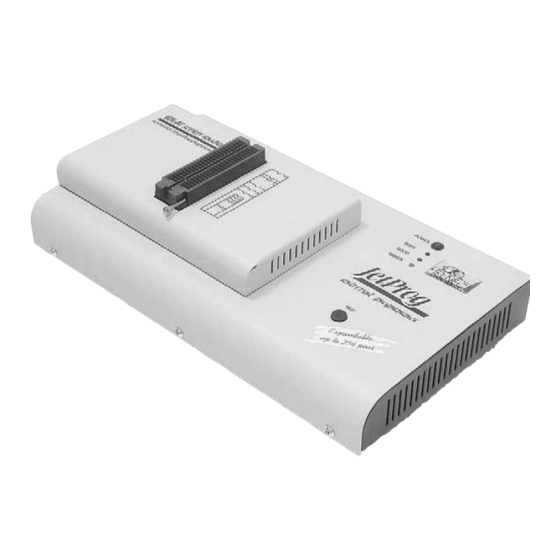
Page 19: Jetprog Elements
LED indicators for work result YES! Button Connector for PC <-> JetProg communication cable Power supply connector Internal use connector Power supply connector Note: Due to low power consumption of JetProg in inactive mode, it doesn't require power switch. When the power LED... -
Page 20: Connecting Jetprog To The Pc
ELNEC s. r. o. indicator glows with a low intensity, the JetProg is in inactive mode. Connecting JetProg to the PC Switch off PC and programmer. Insert the communication cable included with your JetProg programmer package to a free printer port on your PC. If your computer is equipped with only one printer port, substitute the programmer cable for the printer cable. -
Page 21: Manipulation With The Programmed Device
JetProg Manipulation with the programmed device After selection of desired device for your work, you can insert into the open ZIF socket (the lever is up) and close socket (the lever is down). The correct orientation of the programmed device in ZIF socket is shown on the picture near ZIF socket on the programmer's cover. -
Page 22: Technical Specification
ELNEC s. r. o. Technical specification HARDWARE Base unit, DACs • FPGA based IEEE 1284 slave printer port, up to 1MB/s transfer rate • on-board powerful microprocessor (20MHz) supported by FPGA based state machine, 20MHz powered • three D/A converters for VCCP, VPP1, and VPP2, controllable rise and fall time •... - Page 23 JetProg • Flash EPROM: 28Fxxx, 29Cxxx, 29Fxxx, 29BVxxx, 29LVxxx, 29Wxxx, 49Fxxx series, from 256Kbit to 32Mbit, with 8/16 bit data width, full support for LV series • Serial E(E)PROM: 17Xxxx, 18Vxxx, 24Cxxx, 24Fxxx, 25Cxxx, 45Dxxx, 59Cxxx, 85xxx, 93Cxxx, EPCxxx, NVM3060, MDAxxx series, full support for LV series •...
- Page 24 ELNEC s. r. o. • support all devices in DIP with default socket • support devices in non-DIP packages up to 48 pins with universal adapters • programmer is compatible with third-party adapters for non- DIP support Programming speed Note. These times strongly depend on PC speed, LPT port type and operating system free resources.
- Page 25 • temperature 5°C ÷ 40°C (41°F ÷ 104°F) • humidity 20%..80%, non condensing Package included • JetProg, base unit • JetProg, DIL48 socket module • connection cable PC-programmer • diagnostic POD for selftest • anti-dust cover for ZIF socket • switched power adapter 100..240V AC/15V DC/1A •...
- Page 26 ELNEC s. r. o. Additional services • Keep Current. • AlgOR • free technical support (phone/fax/e-mail). • free lifetime software update via Web site.
-
Page 27: Beeprog
BeeProg BeeProg... -
Page 28: Introduction
ELNEC s. r. o. Introduction BeeProg is a first member of new USB-compatible generation of Windows 95/98/Me/NT/2000/XP based ELNEC universal programmers built to meet the strong demand of the developers community for the fast, the all programmer user community of users. - Page 29 BeeProg failure. All the inputs of the BeeProg programmer, including the ZIF socket, connection to PC and power supply input, are protected against ESD up to 15kV. BeeProg programmer performs programming verification at the marginal level of supply voltage, which, obviously, improves programming yield, and guarantees long data retention.
-
Page 30: Beeprog Elements
ELNEC s. r. o. BeeProg elements 48 pin ZIF socket LED indicator power/sleep LED indicators for work result YES! Button LPT connector for PC <-> BeeProg communication cable USB connector for PC <-> BeeProg communication cable Power supply connector ISP connector... -
Page 31: Connecting Beeprog To The Pc
BeeProg Connecting BeeProg to the PC Using LPT port Switch off PC and programmer. Insert the communication cable included with your BeeProg programmer package to a free printer port on your PC. If your computer is equipped with only one printer port, substitute the programmer cable for the printer cable. -
Page 32: Manipulation With The Programmed Device
ELNEC s. r. o. Problems related to the BeeProg interconnection, and their removing have problems with BeeProg interconnection, see section Common notes please. Manipulation with the programmed device After selection of desired device for your work, you can insert into the open ZIF socket (the lever is up) and close socket (the lever is down). - Page 33 These specifications correspond with application notes published of device manufacturers. Used application notes you may find on www.elnec.com, section application notes. Note: Pin no. 1 is signed by triangle scratch on ISP cable connectors. BeeProg ISP cable Warnings: •...
-
Page 34: Selftest And Calibration
ELNEC s. r. o. Note: H/L/read BeeProg driver H/L/read driver connector Selftest and calibration If you feel that your programmer does not react according to your expectation, please run the programmer selftest using Diagnostic POD, enclosed with the standard delivery package. - Page 35 BeeProg • three D/A converters for VCCP, VPP1, and VPP2, controllable rise and fall time • VCCP range 0..8V/1A • VPP1, VPP2 range 0..26V/1A • autocalibration • selftest capability • protection against surge and ESD on power supply input, parallel port connection Socket, pindriver •...
- Page 36 ELNEC s. r. o. • PROM: AMD, Harris, National, Philips/Signetics, Tesla, TI • NV RAM: Dallas DSxxx, SGS/Inmos MKxxx, SIMTEK STKxxx, XICOR 2xxx, ZMD U63x series • PLD: SPLD/CPLD series: Altera, AMI, Atmel, AMD-Vantis, Gould, Cypress, ICT, Lattice, NS, Philips, STM, VLSI, TI, Xilinx •...
- Page 37 Note. These times strongly depend on PC speed, LPT port type and operating system free resources. Therefore are given values of two different PC configurations for comparison. These times are only for illustration, for actual times see www.elnec.com. Device Operation Time A...
- Page 38 ELNEC s. r. o. • ID byte check • special • production mode (automatic start immediately after device insertion) • auto device serial number increment • statistic • count-down mode Buffer operations • view/edit, find/replace • fill/copy, move, byte swap, word/dword split •...
- Page 39 BeeProg Additional services • Keep Current. • AlgOR • free technical support (phone/fax/e-mail). • free lifetime software update via Web site.
-
Page 40: Labprog
ELNEC s. r. o. LabProg+... -
Page 41: Introduction
LabProg+ the ability to handle almost every programmable device in DIL package up to 48 pins without any adapters and/or family modules. This design philosophy allows ELNEC to easily add new devices to the device list, giving you the freedom to implement the optimum device in your designs. - Page 42 LabProg+ to handle any PLCC44 target device in the current device list. Most devices with more than 48 pins require a simple adapter usually available from ELNEC. It is important to remember that in most cases new devices require only a software upgrade since the LabProg+ has 48 true pin drivers, which can perform as required under program control.
-
Page 43: Labprog+ Elements
LabProg+ Advanced design, including protection circuits, original brand components and careful manufacturing allows us to provide a three-year warranty on parts and labour for the LabProg+ (limited 25,000-cycle warranty on ZIF socket). LabProg+ elements 48 pin ZIF (Zero Insertion Force) socket LED indicator power/sleep LED indicators for work result YES! Button... -
Page 44: Connecting Labprog+ To The Pc
ELNEC s. r. o. indicator glows with a low intensity the LabProg+ is in inactive mode. Connecting LabProg+ to the PC Switch off PC and programmer. Insert the communication cable included with your LabProg+ programmer package to a free printer port on your PC. If your computer is equipped with only one printer port, substitute the programmer cable for the printer cable. -
Page 45: Manipulation With The Programmed Device
LabProg+ Problems related to the LabProg+ interconnection, and their removing have problems with LabProg+ interconnection, see section Common notes please. Manipulation with the programmed device After selection of desired device for your work, you can insert into the open ZIF socket (the lever is up) and close socket (the lever is down). -
Page 46: Technical Specification
ELNEC s. r. o. Technical specification HARDWARE Socket, pin drivers and DACs • 48-pin DIL ZIF (Zero Insertion Force) socket accepts both 300/600 mil devices up to 48-pin • Three D/A converters for VCCP, VPP1, and VPP2, with controllable rise and fall time and current limitation •... - Page 47 Notes: • Devices marked * are obsolete, programming with additional module • For all supported devices see actual Device list on www.elnec.com. I.C. Tester • TTL type: 54,74 S/LS/ALS/H/HC/HCT series • CMOS type: 4000, 4500 series • static RAM: 6116 .. 624000 •...
- Page 48 ELNEC s. r. o. Time A conditions: Pentium MMX, 250 MHz, ECP/EPP, Windows 98. Time B conditions: Pentium III, 500 MHz, ECP/EPP on PCI bus, Windows 98. SOFTWARE • Algorithms: only manufacturer approved certified algorithms are used. • Algorithm updates: software updates are available approx.
- Page 49 LabProg+ • POF (Altera), JEDEC (ver. 3.0.A), for example from ABEL, CUPL, PALASM, TANGO PLD, OrCAD PLD, PLD Designer ISDATA etc. PC system requirements See section Introduction/ PC requirements GENERAL • operating voltage 12..15V AC, max.1A or 15..18V DC, max. •...
-
Page 50: Smartprog
ELNEC s. r. o. SmartProg... -
Page 51: Introduction
SmartProg Introduction SmartProg is next member of new generation of Windows 95/98/Me/NT/2000/XP based ELNEC universal programmers. Programmer is built to meet the demands of the development labs and field engineers to universal, but portable programmer. SmartProg is a small, fast and powerful programmer of all kinds of programmable devices. -
Page 52: Smartprog Elements
ELNEC s. r. o. SmartProg programmer is driven by an easy-to-use control program with pull-down menu, hot keys and on-line help. Selecting of device is performed by its class, by manufacturer or simply by typing a fragment of vendor name and/or part number. -
Page 53: Connecting Smartprog To Pc
SmartProg Connector for PC SmartProg communication cable Power supply connector 7 Connector for ISP Note: Due to low power consumption of SmartProg in inactive state, it doesn't require power switch. When the power LED indicator glows with a low intensity the SmartProg is in inactive mode. -
Page 54: Manipulation With The Programmed Device
ELNEC s. r. o. • When connecting the programmer to the PC: FIRST insert the communications cable and THEN the power-supply connector. • When disconnecting the programmer from the PC: FIRST disconnect the power-supply connector and THEN the communication cable. - Page 55 These specifications correspond with application notes published of device manufacturers. Used application notes you may find on www.elnec.com, section application notes. Note: Pin no. 1 is signed by triangle scratch on ISP cable connectors. SmartProg ISP cable Warnings: •...
-
Page 56: Selftest And Calibration
ELNEC s. r. o. H/L/read driver connector Selftest and calibration If you feel that your programmer does not react according to your expectation, please run the programmer selftest using Diagnostic POD, enclosed with the standard delivery package. For optimal results with programmer we recommend you undertake every 6 months, an extended test and to check the calibration. - Page 57 SmartProg • selftest capability ZIF socket, pindriver • 40-pin DIL ZIF (Zero Insertion Force) socket accepts both 300/600 mil devices up to 40-pins • pindriver: 40 TTL pindrivers, universal GND/VCC/VPP pindriver • FPGA based TTL driver provides H, L, CLK, pull-up, pull- down on all pindriver pins, level H selectable from 1.8 V up to •...
- Page 58 • (*2) - there exist only few adapters for devices with more than 40 pins. Therefore think please about more powerful programmer (JetProg, BeeProg, LabProg+), if you need to program devices with more than 40 pins • For all supported devices see actual Device list on www.elnec.com.
- Page 59 SmartProg Device operations • standard: • intelligent device selection by device type, manufacturer or typed fragment of part name • blank check, read, verify • program • erase • configuration and security bit program • illegal bit test • checksum •...
- Page 60 ELNEC s. r. o. • temperature 5°C ÷ 40°C (41°F ÷ 104°F) • humidity 20%..80%, non condensing Package included • SmartProg programmer • connection cable PC-programmer • ISP cable • diagnostic POD for selftest • anti-dust cover for ZIF socket •...
-
Page 61: Preprom-02Alv
PREPROM-02aLV PREPROM-02aLV... -
Page 62: Introduction
ELNEC s. r. o. Introduction PREPROM-02aLV is a small and powerful EPROM, EEPROM, Flash EPROM and serial EEPROM programmer and static RAM tester, designed for professional mobile applications. In addition, PREPROM-02aLV programmer with auxiliary modules support also microprocessors (MCS48, MCS51, PICmicro, AVR), GALs, etc. -
Page 63: Preprom-02Alv Elements
PREPROM-02aLV The PREPROM-02aLV can make for use of DIL to PLCC, SOIC, PSOP socket converters. Taking into consideration the PREPROM-02aLV programmer design, protective circuits, and the components used, the manufacturer is able to provide a three-year warranty on parts and labour for the programmer (limited 25,000-cycle warranty on the ZIF socket). -
Page 64: Connecting Preprom-02Alv Programmer To Pc
ELNEC s. r. o. communication connector, for PC PREPROM-02aLV cable connection connector for power supply connection Note: Due to low power consumption of PREPROM-02aLV in inactive state, it doesn't require power switch. Connecting PREPROM-02aLV programmer to PC Switch off the PC and programmer. Insert the connection cable, included in the PREPROM-02aLV programmer delivery, to the free printer port of PC. -
Page 65: Manipulation With The Programmed Device
PREPROM-02aLV Problems related to the PREPROM-02aLV PC interconnection, and their removing If you have any problems with PREPROM-02aLV interconnection, see section Common notes please. Note for laptop and PREPROM-02aLV users Since the PREPROM-02aLV programmer is supplied with 12V, notebook and/or laptop users may operate their PREPROMs- 02aLV everywhere this voltage is available, e.g. -
Page 66: Technical Specification
ELNEC s. r. o. undertake every 6 months, an extended test and to check the calibration. See instructions for selftest in the Diagnostics menu of PG4UW. Technical specification HARDWARE Socket, pin drivers and DACs • 32-pin DIL ZIF (Zero Insertion Force) socket accepts both 300/600 mil devices up to 32-pin •... - Page 67 • microcontrollers NEC*: uPD78Pxxx series Notes: • Devices marked * are programming with additional module • For all supported devices see actual Device list on www.elnec.com. I.C. Tester • static RAM: 6116 .. 624000 Programming speed • M27C256, programming + verifying, PC486/DX50 : 16 sec •...
- Page 68 ELNEC s. r. o. Supported file formats • unformatted (raw) binary • HEX: Intel, Intel EXT, Motorola S, MOS, Exormax, Tektronix, ASCII-space-HEX • JEDEC PC system requirements See section Introduction/ PC requirements GENERAL • operating voltage 12..15V DC, max. 500mA •...
-
Page 69: Memprog
MEMprog MEMprog... -
Page 70: Introduction
ELNEC s. r. o. Introduction MEMprog is next member of Windows 95/98/ME/NT/2000/XP based ELNEC specialized programmers. Programmer is built to meet the demands of the development labs and field engineers for a specialized memory programmer. MEMprog is little, very fast and powerful portable programmer... -
Page 71: Connecting Memprog Programmer To Pc
MEMprog MEMprog is driven by an easy-to-use control program with pull-down menus, hot keys and on-line help. Selecting of device is performed by its class, by manufacturer or simply by typing a fragment of vendor name and/or part number. Standard device-related commands (read, blank check, program, verify, erase) are enhanced by some test functions (insertion test, signature-byte check), and some special functions (autoincrement). -
Page 72: Manipulation With The Programmed Device
ELNEC s. r. o. • When disconnecting the programmer from the PC: FIRST disconnect the power-supply connector and THEN the communication cable. Problems related to the MEMprog interconnection, and their removing have problems with MEMprog interconnection, see section Common notes please. -
Page 73: Technical Specification
MEMprog Technical specification HARDWARE Programmer • two D/A converters for VCCP and VPP, controllable rise and fall time • VCCP range 0..7V/350mA • VPP range 0..25V/200mA • FPGA based IEEE 1284 slave printer port, up to 1MB/s transfer rate • autocalibration •... - Page 74 • (*2) - there exist only few adapters for devices with more than 40 pins. Therefore think please about more powerful programmer (JetProg, BeeProg, LabProg+), if you need to program devices with more than 40 pins • (*3) - programming with additional module •...
- Page 75 MEMprog • intelligent device selection by device type, manufacturer or typed fragment of part name • blank check, read, verify • program • erase • illegal bit test • checksum • security • insertion test • contact check • ID byte check •...
- Page 76 ELNEC s. r. o. • anti-dust cover for ZIF socket • wall plug adapter 12V DC/500mA, unstabilized • user manual • software • registration card • transport case Additional services • Keep Current • AlgOR • free technical support (hot line)
-
Page 77: T51Prog
T51prog T51prog... -
Page 78: Introduction
ELNEC s. r. o. Introduction T51prog generation Windows 95/98/ME/NT/2000/XP based ELNEC specialized programmers. Programmer is capable to support all today available microcontrollers of MCS51 series (up to 40 pins) and AVR microcontrollers (8-40 pins) by parallel and serial way. T51prog has been developed in close cooperation with Atmel W&M., therefore programmer's hardware is focused to support... -
Page 79: Connecting T51Prog Programmer To Pc
T51prog T51prog performs programming verification at the marginal level supply voltage, which, obviously, improves programming yield, and guarantees long data retention T51prog programmer is driven by an easy-to-use control program with pull-down menu, hot keys and on-line help. Selecting of device is performed by its class, by manufacturer or simply by typing a fragment of vendor name and/or part number. -
Page 80: Manipulation With The Programmed Device
ELNEC s. r. o. Caution! If you don't want to switch off your PC when connecting the T51prog, proceed as follows: • When connecting the programmer to the PC: FIRST insert the communications cable and THEN the power-supply connector. • When disconnecting the programmer from the PC: FIRST disconnect the power-supply connector and THEN the communication cable. - Page 81 These specifications correspond with Atmel application note AVR910: In-System Programming. Used application note you may find on www.elnec.com, section application notes. Note: Pin no. 1 is signed by triangle scratch on ISP cable connectors. ISP cable of T51prog Warnings: •...
-
Page 82: Selftest And Calibration
ELNEC s. r. o. supply is different as expected, no action with device will be executed. Note: H/L/read T51prog driver. H/L/read driver connector Selftest and calibration If you feel that your programmer does not react according to your expectation, please run the programmer selftest using Diagnostic POD, enclosed with the standard delivery package. - Page 83 • Microcontrollers Atmel: AT89Sxxx, AT90Sxxxx, ATtiny, ATmega series Note: • For all supported devices see actual Device list on www.elnec.com. Programming speed Note. These times strongly depend on PC speed, LPT port type and operating system free resources. Therefore are given values of two different PC configurations for comparison.
- Page 84 ELNEC s. r. o. Time A conditions: Pentium MMX, 250 MHz, ECP/EPP, Windows 98. Time B conditions: Athlon, 750 MHz, ECP/EPP on PCI bus, Windows 98. SOFTWARE • Algorithms: only manufacturer approved certified algorithms are used. • Algorithm updates: software updates are available approx.
- Page 85 T51prog GENERAL • operating voltage 12..15V DC, max. 500mA • power consumption 5W max. • dimensions 137x65x40 mm (5.4x2.6x1.6 inch) • weight (without external power adapter) ca. 200g (7.06 oz) • temperature 5°C ÷ 40°C (41°F ÷ 104°F) • humidity 20%..80%, non condensing Package included •...
-
Page 86: 51&Avrprog
ELNEC s. r. o. 51&AVRprog... -
Page 87: Introduction
51&AVRprog Introduction 51&AVRprog is little and powerful portable programmer for MCS51 series and Atmel AVR microcontrollers. 51&AVRprog enables also programming serial EEPROM with interface types IIC (24Cxx), Microwire (93Cxx) and SPI (25Cxx). The programmer is equipped by DIL ZIF 40pin socket. The quality of programmer is completed by comfortable control program. -
Page 88: Manipulation With The Programmed Device
ELNEC s. r. o. only one printer port, substitute the programmer cable for the printer cable. Connect the opposite cable end to the programmer. Screw on both connectors to counter connectors. This is very important mainly for the connector to programmer. -
Page 89: Technical Specification
Notes: • Serial EEPROMs programming is performed little bit slowly. • Hardware of 51&AVRprog programmer isn't capable to support some latest MCS51/AVR chips. • For all supported devices see actual Device list on www.elnec.com. SOFTWARE • Algorithms: only manufacturer approved certified algorithms are used. - Page 90 ELNEC s. r. o. • ID byte check • special: • auto device serial number increment Buffer operations • view/edit, find/replace • fill/copy, move, byte swap, word/dword split • checksum (byte, word) • print Supported file formats • unformatted (raw) binary •...
-
Page 91: Pikprog
PIKprog+ PIKprog+... -
Page 92: Introduction
ELNEC s. r. o. Introduction PIKprog+ is a member of the new generation of Windows 95/98/ME/NT/2000/XP based ELNEC specialized programmers. Programmer is capable to support all currently ® available Microchip PICmicro series microcontrollers (8-40 pins) using parallel and serial algorithms. The PIKprog+... -
Page 93: Connecting Pikprog+ Programmer To Pc
PIKprog+ improves programming yield, and guarantees long data retention. PIKprog+ programmer is driven by an easy-to-use control program with pull-down menu, hot keys and on-line help. Selecting of device is performed by its class, by manufacturer or simply by typing a fragment of vendor name and/or part number. -
Page 94: Manipulation With The Programmed Device
ELNEC s. r. o. • When connecting the programmer to the PC: FIRST insert the communications cable and THEN the power-supply connector. • When disconnecting the programmer from the PC: FIRST disconnect the power-supply connector and THEN the communication cable. - Page 95 It is indicated by (ISP) suffix after name of selected device. These specifications correspond with Microchip application note: In-Circuit Serial Programming™(ICSP™) Guide. Used application note you may find on www.elnec.com, section application notes. Note: Pin no. 1 is signed by triangle scratch on ISP cable connectors.
-
Page 96: Selftest And Calibration
ELNEC s. r. o. • PIKprog+ can supply programmed device only, but target system cannot supply PIKprog+. • PIKprog+ apply programming voltage to target device and checks his value (target system can modify programming voltage). If the programming voltage is different as expected, no action with target device will be executed. - Page 97 Programmer, through ISP connector • Microcontrollers Microchip PICmicro: PIC12Cxxx, PIC16C5x, PIC16Cxxx, PIC17Cxxx, PIC18Cxxx series Notes: • (*1) - suitable adapters are available for non-DIL packages and devices with more than 40 pins • For all supported devices see actual Device list on www.elnec.com.
- Page 98 ELNEC s. r. o. Programming speed Note. These times strongly depend on PC speed, LPT port type and operating system free resources. Therefore are given values of two different PC configurations for comparison. Device Operation Mode Time A Time B...
- Page 99 PIKprog+ • print File load/save • no download time because programmer is PC controlled • automatic file type identification Supported file formats • unformatted (raw) binary • HEX: Intel, Intel EXT, Motorola S-record, MOS, Exormax, Tektronix, ASCII-SPACE-HEX PC system requirements See section Introduction/ PC requirements GENERAL •...
-
Page 100: Pikprog
ELNEC s. r. o. PIKprog... -
Page 101: Introduction
PIKprog Introduction PIKprog is little and powerful portable programmer for Microchip PIC series of microcontrollers. PIKprog enables also programming serial EEPROM with interface types IIC (24Cxx), Microwire (93Cxx) and SPI (25Cxx). The programmer is equipped by DIL ZIF 40pin socket. The quality of programmer is completed by comfortable control program. -
Page 102: Manipulation With The Programmed Device
ELNEC s. r. o. programmer through a mechanical printer switch. Use of an electronic printer switch isn't possible. Connect the mains connector of the power supply (or wall-plug power supply self) to a mains plug, connect the connector to the appropriate programmer's connector. Then, on the programmer lights up LED POWER and the programmer PIKprog is ready to run. -
Page 103: Technical Specification
8/16/18/28/40 pins • Serial E(E)PROM: 24Cxxx, 24Fxxx, 25Cxxx, 59Cxxx, 85xxx, 93Cxxx series Notes: • Serial EEPROMs programming is performed little bit slowly. • For all supported devices see actual Device list on www.elnec.com. SOFTWARE • Algorithms: only manufacturer approved certified algorithms are used. - Page 104 ELNEC s. r. o. • checksum (byte, word) • print Supported file formats • unformatted (raw) binary • HEX: Intel, Intel EXT, Motorola S, MOS, Exormax, Tektronix, ASCII-space-HEX PC system requirements See section Introduction/ PC requirements GENERAL • operating voltage 15..20V DC, max. 200mA •...
-
Page 105: Seeprog
SEEprog SEEprog... -
Page 106: Introduction
ELNEC s. r. o. Introduction SEEprog is universal programmer of all serial EEPROM in 8- pin DIL package. SEEprog programs EEPROM with interface IIC, SPI and Microwire, and also specialty as for example digital thermometers. The programmer supports LV (3.3V) devices too. -
Page 107: Manipulation With The Programmed Device
SEEprog programmer through a mechanical printer switch. Use of an electronic printer switch isn't possible. Connect the mains connector of the power supply (or wall-plug power supply self) to a mains plug, connect the connector to the appropriate programmer's connector. Then, on the programmer lights up LED POWER and the programmer SEEprog is ready to run. -
Page 108: Technical Specification
ELNEC s. r. o. Technical specification HARDWARE Socket and control of pins: • DIL/ZIF socket (300mil) • each pin is possible to set in position Low and Pull-up • from each pin is possible to read • support of Low Voltage devices For works with serial EEPROM are used nearest 8 pins to lever, unused pins are not connected. - Page 109 SEEprog File format conversion • binary • HEX: Intel, Intel EXT, Motorola S, MOS, Exormax, ASCII - space – HEX, Tektronix PC systems requirements See section Introduction/ PC requirements GENERAL • power supply: 8V...15V, max.50mA • dimensions 137x65x40 mm (5.4x2.6x1.6 inch) •...
-
Page 110: Software
ELNEC s. r. o. Software... -
Page 111: The Programmer Software
Using the programmer software The control program delivered by ELNEC, included on the CD in your package, is granted to be free from any viruses at the moment of delivery. To increase their safety our programs include a special algorithm for detecting possible virus infections. - Page 112 In Windows environment: double click to icon PG4UW. After start, control program PG4UW automatically scan all existing ports and search for the connected any ELNEC's programmer. Program PG4UW is common for all the ELNEC's programmers, hence program try to find all supported (JetProg, BeeProg, LabProg+, SmartProg, PREPROM-02aLV, MEMprog, T51prog, 51&AVRprog, PIKprog+, PIKprog and...
- Page 113 Software Description of the user screen Windows program PG4UW Header bar the name, copyright statement and version of the PG4UW control program Menu bar list of basic functions Filename information on the currently loaded file in buffer Programmer window information about the status of the programmer and PG4UW Addresses window organization,...
-
Page 114: File
ELNEC s. r. o. List of hot keys <F1> Help Calls Help <F2> Save Save file <F3> Load Load a file into the buffer <F4> Edit Viewing/editing of buffer <F5> Select/default Target-device selection from 10 last selected devices list <Alt+F5>... - Page 115 Software When the check box Automatic file format recognition is unchecked program allows user to manually select wished file format from list of available file formats on panel Selected file format. When Binary file format is selected, there can be specified Buffer start value.
- Page 116 ELNEC s. r. o. (big endian). Standard save file operation is using little endian byte order. The reserved key <F2> will bring out this menu from any menu and any time. File / Load project This option is used for loading project file, which contains device configuration buffer data saved and user interface configuration.
- Page 117 Software The second (middle) windows displays information about actual program configuration including currently selected device, active programmer, date, time. These actual program settings are used for creation of project description header. The third (bottom) window is user editable and contains project description (arbitrary text), which usually consists of project author and some notes.
-
Page 118: Device
ELNEC s. r. o. User can directly edit user defined project description only. Device name, manufacturer, project date and program version are generated automatically by program. File / Load encryption table This command loads the data from binary file from disk and it saves them into the part of memory, reserved for an encryption (security) table. - Page 119 Software Device / Select device ... This window allows selecting the desired type of the device from all devices supported by current programmer. It is possible to choose device by name, by type or by manufacturer. Selected device is automatically saved to buffer of default devices (max.
- Page 120 ELNEC s. r. o. manufacturer name and/or device number in a search box (use a key <Space> as a separation character) and press <Enter> or click OK button. Press a key <Esc> or click Cancel button at any time to cancel device selection without affecting the currently selected device.
- Page 121 Software a message will be displayed indicating this as an unknown or not supported device. If more devices with identical chip ID and manufacturer's ID were detected, the list of these devices will be displayed. A corresponding device can be chosen from this list by selecting its number (or manufacturer name) from list and press <Enter>...
- Page 122 ELNEC s. r. o. Split (default none) this option allows to set special mode of buffer when programming or reading device. Following table describes buffer to device and device to buffer data transfer - group Insertion test: insertion test (default ENABLE)
- Page 123 Software in dialog Serialization. In this section two choices are available: 1. Ignore not programmed serial values 2. Add not programmed serial values to file Ignore not programmed serial values means the not programmed serial values are ignored and no action is done with them.
- Page 124 ELNEC s. r. o. Address option specifies the buffer address, where serial value has to be written. Note that address range must be inside the device start and device end addresses. Address must be correctly specified so the last (highest or lowest) byte of serial value must be inside device start and device end address range.
- Page 125 Software Save to buffer option specifies the serial value byte order to write to buffer. This option is used for Bin S / N mode (for ASCII mode it has no effect). Two options are available: • LSByte first (used by Intel processors) will place the Least Significant Byte of serial number to the lowest address in buffer.
- Page 126 ELNEC s. r. o. ”xx” mean user data programmed to device Serial numbers are written to device from address 7FFFCH to address 7FFFFH because serial number size is 4 bytes. 2. Following example shows usage of serial number split into RETLW instructions for Microchip PIC16F628 devices.
- Page 127 Software or by loading file with proper content). The bottom 8 bits of each RETLW instruction are not important now, because serialization will write correct serial number bytes at bottom 8 bits of each RETLW instruction. The buffer content before starting device program will look for example as following: Address Data 0000040...
- Page 128 ELNEC s. r. o. When ”Split serial number at every 4 byte(s)” is set, the buffer content will look as: Byte buffer organization: Address Data 0000080 CD xx xx xx AB xx xx xx 34 xx xx xx 12 Word16 buffer organization:...
- Page 129 Software Start label defines the start label in input file. The reading of serial values from file starts from defined start label. From file serialization file format From file serialization input file includes addresses and arrays of bytes defining buffer addresses and data to write to buffer.
- Page 130 ELNEC s. r. o. Optional part is delimited from the first data part by character “ , “ (comma) and its structure is the same as in the first data part, i.e. address and following array of data bytes. Characters with special use: [ ] - labels must be defined inside square brackets ',' –...
- Page 131 Software i.e. the last byte of this value will be written to address $FFFFF. Note: Address for Serialization is always assigned to actual device organisation and buffer organisation that control program is using for current device. If the buffer organisation is byte org. (x8), the Serialization Address will be byte address.
- Page 132 ELNEC s. r. o. Failure number operations which where successfully completed Total number of all operations Count down informs about Count down activity (Enabled or Disabled) Remains informs about remaining number of device operations to do Successful operation means any device operation of these, which is completed without errors: •...
- Page 133 Software The menu command Device / Device options / Operation options allows to set another working area as the standard. Device / Read This command allows reading whole device or its part into the buffer. The control program reports a finish of this action by write a message to INFO window.
-
Page 134: Buffer
ELNEC s. r. o. Device / Test This command executes a test with device selected from list of supported devices (e.g. static RAM) on programmers, which support this test. Device / Device info The command provides additional information about the... - Page 135 Software address block (or part) will be filled by topical blank character. swap bytes command swaps a high- and low- order of byte pairs in current buffer block. This block must start on even address and must have an even number of bytes.
- Page 136 ELNEC s. r. o. Defines end address of selected block in buffer. External editor Defines path and name of external program, which has to be used as text viewer for selected block of buffer. By default is set simple text editor Notepad.exe, which is standard part of all versions of Windows.
- Page 137 Software change mode view / edit switch the mode of buffer data view between 1 bit and 8 bit view. It can be also do by mouse clicking on the button to the right of View/Edit mode buffer indicator. This button indicates actual data view mode (1 bit or 8 bit), too.
- Page 138 ELNEC s. r. o. Buffer / Fill random data If this command is selected, the content of the buffer will be filled with random data. The reserved key <Shift+Ctrl+F2> will bring out this menu from any menu and any time.
-
Page 139: Options
Software Insert checksum: This is special item used for select which kind of checksum will be written into the buffer when, the Calculate & insert was executed. Insert at address: This is special item that specifies an address from the buffer where a result of chosen checksum will be written, when the Calculate &... - Page 140 ELNEC s. r. o. In group When current file is modified by another process can be set mode of reloading of actually loaded (current) file. There are three choices: 1. Prompt before reloading file 2. Reload automatically 3. Ignore change scanning of current file Load file format allows to set mode of file format recognition for loading files.
-
Page 141: Save Options
Software This page allows you to select another language for user interface such as menu, buttons, dialogs, information and messages. It also allows to select wished help file in another language. For another language support of user interface the language definition file is required. Sound Sound page allows user to select the sound mode of program. - Page 142 ELNEC s. r. o. Options / View / Device options before device operation Choose this command to enable/disable display of Device options before device operation is confirmed. Options / Display errors This option allows you set a form of errors displaying as a result of programmed data verifying.
- Page 143 Software Pressing key <Enter> or button OK initiates scanning for programmer by set parameters. There is same activity as at start the control program. The command clears a list of default devices without the current device, if the new selected programmer supports this one.
- Page 144 ELNEC s. r. o. operation executing will be cancelled by pressing key <Esc> during waiting for insert/remove a device to/from ZIF. This feature is available for JetProg, BeeProg and LabProg+ programmer only. Note: During waiting for an insertion a new device into ZIF socket, the LED BUSY on the programmer is blinking.
-
Page 145: Diagnostics
Software mode is used for prevent operator from modify buffer or device settings due to insignificance. Protected mode is suitable for the programming of a large amount of the same type of devices. There are two ways how to switch program to Protected mode: 1. -
Page 146: Help
ELNEC s. r. o. Diagnostics / IC test This command activates a test section for ICs separated by compatibility to any libraries (on distribution CD). First select an appropriate library, wished device and then a mode for test vectors run (Loop, Single step). Control sequence and test results are displayed to Log window. - Page 147 Software Help / Supported devices This command displays list of all devices supported by at least one type of all supported programmers. It is useful especially when user wants to find any device supported by at least one type of programmers. Prefix ”g_”...
-
Page 148: Common Notes
ELNEC s. r. o. Common notes... -
Page 149: Software
Common notes Software PG4UW is common control program for all of the ELNEC programmers. Thus, during work with him it is possible to find some items, those refer not to current selected programmer. Some special devices (e.g. Philips Coolrunner family) require external DAT files, that aren’t present in standard PG4UW SW... -
Page 150: Hardware
ELNEC s. r. o. relative path to file that has to be loaded, file format detected automatically /Program[:switch] forces start of ”Program device” operation automatically when program is starting, or even if program is already running, also one of following optional... -
Page 151: Isp (In-System Programming)
• Any devices connected to target system must be connected to common earth point too. Direction connect ELNEC programmer to target system: During in-system programming you connect two electrical devices – ISP programmer and target system. Unqualified connection can damage these devices. - Page 152 For in-system programmable devices manufacturers publish application notes. Design of ELNEC programmers together with respect of these application notes allow proper In-system programming. Condition is exactly respect these application notes. Applications notes, which ELNEC use in ISP programmers, are published in www.elnec.com, section Application notes.
- Page 153 Common notes Example of application note Microcontrollers Atmel AVR and AT89Sxxx series This application note is used in T51prog. This interface corresponds with Atmel application note AVR910: In-System Programming. This application note describes recommended ISP interface connector layout in target system (top view).
- Page 154 ELNEC s. r. o. ELNEC’s recommended circuit for ATMEL AVR: ISP connector target device target system DATA IN DATA OUT RESET ATMEL AVR 1N4148 R1 22k 100k MOSI R2 22k MISO R3 22k RESET 1u/10V reset circuit ELNEC’s recommended circuit for AT89Sxxx:...
- Page 155 ® maximal power supply, therefore VDD pin of PICmicro must be isolated from rest of target system during programming. ELNEC’s recommended circuit for PICmicro: ISP connector target device target system DATA...
- Page 156 P0.4 and P0.5 signals are used by the P87LPC76x for In- system programming, therefore target system mustn’t affect these signals during In-system programming to avoid programming errors. ELNEC’s recommended circuit for P87LPC76x: ISP connector target device target system P0.4 P0.5...
- Page 157 P0.4 and P0.5 signals are used by the P89LPC9xxx for In- system programming, therefore target system mustn’t affect these signals during In-system programming to avoid programming errors. ELNEC’s recommended circuit for P89LPC9xx: ISP connector target device target system P0.4 P0.5...
- Page 158 SDIO(PB7) and SCLK(PB5) signals are used by the EM6812 for In-system programming, therefore target system mustn’t affect these signals during In-system programming to avoid programming errors. ELNEC’s recommended circuit for EM6812: ISP connector target device target system SDIO(PB7) SCLK(PB5)
- Page 159 In-system programming, therefore target system mustn’t affect these signals during In-system programming to avoid programming error. As well, RESET pin should be isolated (or not affected) during programming the device. ELNEC’s recommended circuit for uPD78Fxxxx: ISP connector target device target system...
-
Page 160: Other
OS's (Windows 95/98/Me/NT/2000/XP). There is needful for regular running of control program for any ELNEC programmer that printer port, on which is programmer connected, must be reserved for this programmer only. Otherwise, any other program must not simultaneously to use (or any way to modify) this printer port. -
Page 161: Troubleshooting And Warranty
Troubleshooting and warranty Troubleshooting and warranty... -
Page 162: Troubleshooting
Send the completed form by mail or fax to ELNEC (fax number in the control program, menu Help / About) or to your local dealer. If you send the form by fax please use black ink, a good pen and large letters easily to read. -
Page 163: If You Have An Unsupported Target Device
• If your programmer is diagnosed as defective, consult your local dealer or ELNEC about the pertinent repair center in your country. Please carefully include the following items in the package: •... -
Page 164: Warranty Terms
Please also see Troubleshooting section. Manufacturer: : ELNEC s. r. o., Post 5, P. O. Box 22, SK - 08005 Presov, Slovakia : +42151/77 34 328, 77 31 007, fax 77 32 797 www.elnec.com, (nospam version) elnec at elnec dot com... -
Page 165: Appendix
Appendix Appendix... -
Page 167: Appendix A - Device Problem Report Form
Problem Report form (Support section), if occurred any problem during work with programmable device and ELNEC programmers. If you haven't access to Internet, please make a copy of this page to A4. DEVICE PROBLEM REPORT... -
Page 168: Appendix B - Keep-Current Service
ELNEC ships off the latest version of the programmer software and updated user documentation (Keep-Current package). A Keep-Current service is your task-free guarantee that you are exploiting your ELNEC programmers and doing high quality programming at maximum and with minimal costs. -
Page 169: Appendix C - Algor Service
This service may be used also for requesting new features of the control program. AlgOR process is simple. The user sends to ELNEC a request for additional support for XXX device to the control program (we may ask for up-to-date data sheets and samples, if needed). - Page 170 ELNEC. • AlgOR service is free of charge. Therefore we do not accept any claims regarding this service. ELNEC s.r.o. reserves the right to set the dispatching priority on the particular tasks according to its own judgment.
-
Page 171: Appendix D - Registration Card
If the registration card is missing from your standard programmer delivery package please use a copy of the form below and send it to ELNEC. We remind you that without the "Extended warranty" document only the standard 6-month warranty is granted. -
Page 173: Appendix E - Ce Certificates
Appendix Appendix E - CE certificates E/1 - CE certificate JetProg... - Page 174 ELNEC s. r. o. E/2 - CE certificate BeeProg...
- Page 175 Appendix E/3 - CE certificate LabProg+ LabProg+ is a new name of LabProg-48LV.
- Page 176 ELNEC s. r. o. E/4 - CE certificate SmartProg...
- Page 177 Appendix E/5 - CE certificate PREPROM-02aLV...
- Page 178 ELNEC s. r. o. E/6 - CE certificate MEMprog...
- Page 179 Appendix E/7 - CE certificate T51prog...
- Page 180 ELNEC s. r. o. E/8 - CE certificate 51&AVRprog...
- Page 181 Appendix E/9 - CE certificate PIKprog+...
- Page 182 ELNEC s. r. o. E/10 - CE certificate PIKprog...
- Page 183 Appendix E/11 - CE certificate SEEprog...
Need help?
Do you have a question about the JetProg and is the answer not in the manual?
Questions and answers