Table of Contents
Advertisement
Quick Links
FCHC
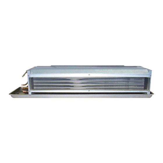
Installation Manual
FCHU
Horizontal Concealed/
Horizontal Ultra Thin
Units
Fan Coil Unit (FCU)
Precautions and preparations listed are for general knowledge and to define basic guidelines. Local codes and existing practices should be observed and preformed by a professional.
Due to ICE AIRs ongoing product development programs, the information in this document is subject to change without notice.
Advertisement
Table of Contents

Related Manuals for ICE AIR FCHC


Summary of Contents for ICE AIR FCHC
- Page 1 FCHC Installation Manual FCHU Horizontal Concealed/ Horizontal Ultra Thin Units Fan Coil Unit (FCU) Precautions and preparations listed are for general knowledge and to define basic guidelines. Local codes and existing practices should be observed and preformed by a professional.
-
Page 2: Table Of Contents
Contents Thank you for purchasing and installing the ICE AIR FCU (Fan Coil Unit). ICE AIR is a leading supplier of FCUs, offering superior quality, General/Safety Information ......2 reliability and efficiency for our customers. Overview/Application Note/Prerequisite ..3 ATTENTION INSTALLING PROFESSIONAL FCHC Nomenclature ........ -
Page 3: Overview/Application Note/Prerequisite
5. Dedicated electrical circuitry and power ISOMETRIC VIEW (FRONT-LEFT) supply is required to properly energize the ICE AIR unit. Verify the amperage of JUNCTION BOX the dedicated electrical service to the unit is correct and the unit can reach the power supply. -
Page 4: Fchc Nomenclature
FCHC Nomenclature Model Selection FCHC 08 E M X A G A P M F Item Number 9 10 11 12 13 14 15 16 17 18 19 20 21 22 23 Primary Part Secondary Parts Valve Package Parts 5- 115V - 1Ph - 60Hz... -
Page 5: Fchc Valve Package Nomenclature
FCHC Valve Package Nomenclature Model Selection FCHC 08 E M X - 22 A G A P M F Item Number 9 10 11 12 13 14 15 16 17 18 19 20 21 22 23 Primary Part Secondary Parts... -
Page 6: Fchu Nomenclature
FCHU Nomenclature Model Selection FCHU 06 E M X 22 A G A A P M F Item Number 9 10 11 12 13 14 15 16 17 18 19 20 21 22 23 Primary Part Secondary Parts Valve Package Parts 5- 115V - 1Ph - 60Hz 8- 208V - 1Ph - 60Hz 7- 277V - 1Ph - 60Hz... -
Page 7: Fchu Valve Package Nomenclature
FCHU Valve Package Nomenclature Model Selection FCHU 08 E M X - 01 A G A P M F Item Number 9 10 11 12 13 14 15 16 17 18 19 20 21 22 23 Primary Part Secondary Parts Valve Package Parts 01- Line Voltage 2 Way MV* Normally Closed 11- 24V 2 Way MV* Normally Closed... -
Page 8: Before You Begin
Before You Begin Horizontal Concealed 1. Locate the unit where it can evenly distribute air throughout the room without obstructions. Units should be installed no closer than 12” apart when two units are side by side. A vertical clearance of 60” should be maintained between units. -
Page 9: Installation
Isolator of a flexible hose or rigid pipe. The piping system should be flushed to remove dirt, Washer The ICE AIR unit is delivered with a pipe shavings, chips and other foreign Hex Nut Dispensable Filter. Dispensable Filters should Threaded... -
Page 10: General Electric
General Electric Line Voltage General Line Voltage Wiring Wiring, including the electrical ground, must comply with the National Be sure the available power is the same voltage and phase shown Electrical Code as well as all applicable local codes. Refer to the on the unit serial number plate. - Page 11 4 Pipe System Room Temp Probe Circuit #1 To Low Voltage Thermostat Transformer CON1 COOL Motor HEAT1 HEAT2 ELA-8693/ELA-8694 Relay Board Wire Chart Front Back Common 24VAC Cooling Heat — Not in Use — Optional Lo-Cool Me-Cool Mount Wiring — Not in Use — Legend: Component Outline Cooling...
-
Page 12: System Cleaning And Flushing
System Cleaning and Flushing Cleaning and flushing the unit is the most important step to ensure proper start-up and continued efficient operation of the system. Follow the instructions below to properly clean and flush the system: 1. Verify that electrical power to the unit is OFF. 2. -
Page 13: Troubleshooting
If unit is not operating, conduct the following checks: IMPORTANT: It is not the intent of this maintenance manual to resolve any problems with the operation of your ICE AIR unit. 1. Check the electrical connections. Please contact a trained servicer or building maintenance 2. -
Page 14: System Check List
Allow unit to run 15 minutes in each mode before taking data. Temperature Differential Do not connect service manifold gauges during start up unless Water Pressure IN instructed by ICE AIR service tech. Water Pressure OUT (PSI) Pressure Differential (PSI) Flow Rate (GPM) -
Page 15: Warranty/Contact Information
The Company is not obligated under this warranty for specifi cally agreed to in writing, ICE AIR includes no fi eld default. ICE AIR is not responsible for service to correct...
Need help?
Do you have a question about the FCHC and is the answer not in the manual?
Questions and answers