
Related Manuals for AMS TDC-GPX2


Summary of Contents for AMS TDC-GPX2
- Page 1 Eval Kit Manual DN[Document ID] TDC-GPX2 Standard Board GPX2-EVA-KIT ams Eval Kit Manual Page 1 [v1-00] 2016-Oct-20 Document Feedback...
-
Page 2: Table Of Contents
TDC-GPX2 Standard Board Content Guide Introduction .......................... 3 Quick Start Guide ......................... 4 Install the Software....................... 4 Install the Hardware: ......................4 Software ..........................5 Hardware Description......................6 Introduction .......................... 6 Input Signals lines ........................ 7 3.2.1 CMOS Inputs ........................7 3.2.2... -
Page 3: Introduction
Introduction The GPX2-EVA-KIT evaluation system is designed as a platform for a quick and easy start of evaluation of the TDC-GPX2 time-to-digital converter. The kit offers a graphical user interface for user-friendly configuration and extensive testing of the TDC-GPX2. For a proper use of the evaluation system, we strongly recommended to refer to the latest TDC-GPX2 datasheet. -
Page 4: Quick Start Guide
TDC-GPX2 Standard Board Quick Start Guide This section describes how to set up the GPX2-EVA-KIT, establish basic operation and make measurements quickly. Install the Software It is crucial to install the software before connecting the evaluation kit to your computer. A default driver loading of your OS may interfere with correct installation. -
Page 5: Software
TDC-GPX2 Standard Board Connect the power supply. Make sure it is set to 6 V supply voltage. The green LED on the evaluation kit should be on. Connect your signal source. Software Excecute the GPX2 Frontpanel software. The communication status should be green ... -
Page 6: Hardware Description
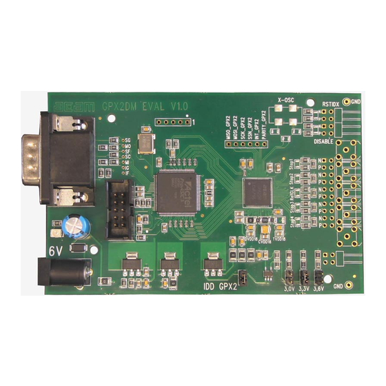
SPI interface and can use the same to read data. In addition, the FPGA manages the readout from the serial LVDS outputs of the TDC-GPX2. The SPI signals are available via additional pads [3]. A jumper selects the supply voltage as 3.0 V, 3.3 V or 3.6 V [4]. A separate jumper allows measuring the current into the TDC-GPX2 [5]. -
Page 7: Input Signals Lines
TDC-GPX2 Standard Board Input Signals lines The board is prepared to connect directly CMOS input signals or LVDS signals. Figure 3: Input section 100R 100k LVDS N.c. LVDS LVDS CMOS In CMOS LVDS CMOS GND P/N In 3.2.1 CMOS Inputs On the board there is a 10 Ohm series resistor. -
Page 8: Software Description
TDC-GPX2 Standard Board Software Description Main Window, REFCLK Page The software start with the following main window: Figure 4: GPX2 evaluation software main window The main menu offers the typical functions to load and save configurations, to run a measurement, to open the graph and register windows as well as a help. -
Page 9: Stop Page
TDC-GPX2 Standard Board The first page, “REFCLK”, allows to select the reference input as well as the definition of the LSB. REFCLK_DIVISIONS defines the LSB at the output interface as fraction of the reference clock period. The most convenient way is applying an LSB of 1ps by configuring REFCLK_DIVISIONS to the picosecond value of the reference clock period. -
Page 10: Interface Page
TDC-GPX2 Standard Board Interface Page On this page the communication as well as the output data format is defined. In any case, on the evaluation kit all communication is done via the on-board FPGA. Figure 7: Kit Content ams Eval Kit Manual... -
Page 11: Avoiding Configuration Conflicts
TDC-GPX2 Standard Board Avoiding Configuration Conflicts Some combinations of parameter settings can prohibit operation or cause erroneous results. Some of these combinations are indicated with a red bar. User should avoid such configurations since the results may be difficult to interpret or faulty at all. -
Page 12: Register Content
TDC-GPX2 Standard Board Register Content A separate window shows the register content in the GUI and the TDC-GPX2. Separate pages display configuration data and result data. Changing the hexadecimal values will change the configuration in the GUI accordingly. With “Write Config” the updated configuration is downloaded into the chip. -
Page 13: Graph Window
TDC-GPX2 Standard Board Graph Window The graphical display allows to select which data shall be displayed. The shape of the individual curves can be modified individually. Move the mouse over the line symbol and press the right mouse button. A menu with many options will pop up. - Page 14 TDC-GPX2 Standard Board The text file can then be analized with a table calcluation program. Figure 12: Exported data format Known Errors Software Hang-up Once in a while, typically during tests in the temperature chamber, it may happen that the software hangs up. This is most likely to erroneous reading from the FIFO and related in the FPGA.
-
Page 15: Schematics, Layers And Bom
TDC-GPX2 Standard Board Schematics, Layers and BOM Figure 13: GP30-EVA BOARD Schematics 1 ams Eval Kit Manual Page 15 [v1-00] 2016-Oct-20 Document Feedback... - Page 16 TDC-GPX2 Standard Board Figure 14: GP30-EVA BOARD Schematics 2 ams Eval Kit Manual Page 16 [v1-00] 2016-Oct-20 Document Feedback...
- Page 17 TDC-GPX2 Standard Board Figure 15: GP30-EVA BOARD Schematics 3 ams Eval Kit Manual Page 17 [v1-00] 2016-Oct-20 Document Feedback...
- Page 18 TDC-GPX2 Standard Board Figure 16: GPX2-EVA BOARD Layout: Top layer Figure 17: GPX2-EVA BOARD Layout: Layer2 ams Eval Kit Manual Page 18 [v1-00] 2016-Oct-20 Document Feedback...
- Page 19 TDC-GPX2 Standard Board Figure 18: GPX2-EVA BOARD Layout: Layer 2 Figure 19: GPX2-EVA BOARD Layout: Bottom layer ams Eval Kit Manual Page 19 [v1-00] 2016-Oct-20 Document Feedback...
- Page 20 TDC-GPX2 Standard Board Figure 20: GPX2-EVA BOARD Layout: Assembly layer ams Eval Kit Manual Page 20 [v1-00] 2016-Oct-20 Document Feedback...
- Page 21 TDC-GPX2 Standard Board Figure 21: Bill of Materials for GP30-EVA BOARD Item Reference Part Name PART DESC TYPE A3P250/VQ100 ProASIC3 Flash A3P250VQG100 Family FPGA C2 C6 C7 C805,100n CHIP- C11 C14 CAPACITOR C16 C17 C18 C20 C21 C22 C30 C33...
- Page 22 TDC-GPX2 Standard Board Item Reference Part Name PART DESC TYPE R805,9k1 CHIP-RESISTOR R805,3k3 CHIP-RESISTOR R805,1M1 CHIP-RESISTOR R805,60k4 CHIP-RESISTOR R805,910k CHIP-RESISTOR R805,604k CHIP-RESISTOR R805,1M87 CHIP-RESISTOR R805,820k CHIP-RESISTOR R7 R8 R38 R805,100k CHIP-RESISTOR R39 R44 R50 R52 R53 R54 R55 R56 R57 R58...
-
Page 23: Ordering & Contact Information
TDC-GPX2 Standard Board Ordering & Contact Information Ordering Code Part Number Description GPX2-EVA-KIT 220310001 TDC-GPX2 Eval Kit for QFN40 version including PICOPROG and cables GPX2-EVA-BOARD 220310003 TDC-GPX2 evaluation board for QFN64 Buy our products or get free samples online at: www.ams.com/ICdirect Technical Support is available at: www.ams.com/Technical-Support... -
Page 24: Copyrights & Disclaimer
AG shall not be liable to recipient or any third party for any damages, including but not limited to personal injury, property damage, loss of profits, loss of use, interruption of business or indirect, special, incidental or consequential damages, of any kind, in connection with or arising out of the furnishing, performance or use of the technical data herein. -
Page 25: Revision Information
TDC-GPX2 Standard Board Revision Information Changes from previous version 0-02 to current revision 1-00 (2016-Oct-20) Page Transfer from preliminary to release version 1-00 Note: Page numbers for the previous version may differ from page numbers in the current revision. Correction of typographical errors is not explicitly mentioned. - Page 26 Mouser Electronics Authorized Distributor Click to View Pricing, Inventory, Delivery & Lifecycle Information: GPX2-EVA-KIT...
Need help?
Do you have a question about the TDC-GPX2 and is the answer not in the manual?
Questions and answers