Table of Contents
Advertisement
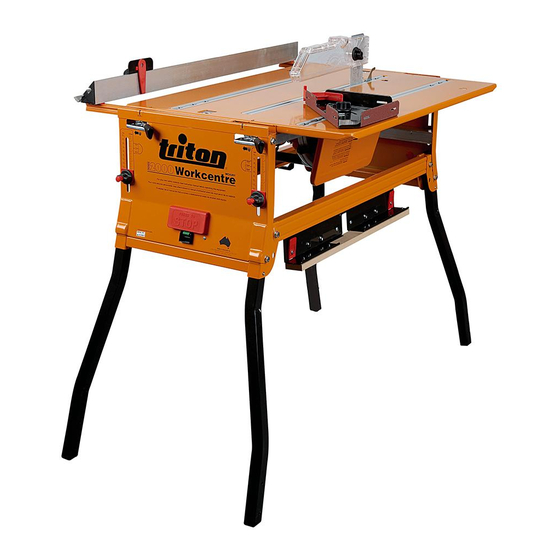
Assembly & Operating Manual
TABLESAW MODE
Thank you for your purchase of the Triton Series 2000 Workcentre. If properly set up,
and fitted with a good quality saw and blade, it will give you great accuracy and many
years of trouble-free service.
To set up properly, make sure you follow this manual. Otherwise you could spend
many unnecessary hours, and still not get it right.
TERMS AND SYMBOLS USED IN THIS MANUAL
"Front of the Workcentre" refers to the end which has the switchbox. The "left-hand &
right-hand side" are when viewed from the front of the Workcentre.
Safety warning or safety instruction.
Possible fitting or operating difficulty.
Handy hint & tip.
Basic assembly diagram
Fitting the Triton Precision Saw
Fitting other brands of saw
Final assembly
A WORD FROM THE MANUFACTURERS
2
3
4-5
6-7
8-11
Workcentre
Workcentre
CROSSCUT MODE
Take special note of this instruction.
!
WARNING! Do not attempt this.
Operating - Table saw
Operating - Crosscut saw
Warranty & Mailing List
Quality
Endorsed
Company
12-13
13-14
15-23
24-27
28
Advertisement
Table of Contents

Related Manuals for Triton 2000


Summary of Contents for Triton 2000
- Page 1 CROSSCUT MODE A WORD FROM THE MANUFACTURERS Thank you for your purchase of the Triton Series 2000 Workcentre. If properly set up, and fitted with a good quality saw and blade, it will give you great accuracy and many years of trouble-free service.
-
Page 2: Table Of Contents
Fitting Kit m. M6 x 40mm Philips- M8 x 50 Bolt (8) head Screws (4) n. M6 Flange Nuts (4) Push-stick o. Alignment Cams for Triton Saw Scale hanger (2) (2 sets packed in separate bag) Pointer Labels (1) Page 2... - Page 3 STEP 1: Fit the Legs (D) to each End Panel (B & C). Before fitting, check that each leg splays outwards as shown, and that you have fitted the Leg Locking Pin (a) with the spring- loaded ball facing outwards. Tighten the bolts so that the legs are firm, but still free to pivot.
-
Page 4: Head
Fitting the Triton 235mm Precision Power Saw For other brands of saw go to Page 6. FITTING THE SLIDE CHASSIS Place the Slide Chassis (L) in the bearing channels with the red plastic catch and red bearing spacers closest to the front panel (the switch box end) and the flanges upwards. - Page 5 Fitting the Triton 235mm Precision Power Saw (cont.) ALIGNING THE SAW Position the chassis halfway between the end panels. Adjust the fence in close to the blade and lock it. Make sure the blade is vertical by comparing it to the face of the fence.If necessary, loosen the nut holding the Blade Angle Trimmer (circled), and adjust the blade angle.
- Page 6 Fitting other brands of power saw FITTING THE SLIDE CHASSIS Place the Slide Chassis (L) in the bearing channels with the red plastic catch and red bearing spacers closest to the front panel (the switch box end) and the flanges upwards. Enter two bearings in the cutouts in the channels.
- Page 7 Fitting other brands of power saw (cont.) ALIGNING THE SAW Have the chassis midway between the end panels and lock the rip Push saw locator fence close to the blade. Compare the blade angle to the vertical not the saw face of the fence, and if necessary adjust the blade angle (using the saw’s adjuster) until they are parallel vertically.
- Page 8 FITTING THE SIDE GUARD Slide the two sections of the Side Guard (K) together until they fit between the pivot brackets on the slide chassis. Loosely fit the short Nyloc nut Philips-head screw (i) and a Nyloc nut (h) to hold them together. on inside Fit the two longer Philips-head screws (j) and Nyloc nuts through the pivot brackets and into the guard flanges.
- Page 9 Hold 2 straight pieces of wood lightly against the blade. The overhead guard support should fit between the pieces. If not you may have to adjust the saw position slightly. This is only likely if you have a very thin kerf blade (2.0 - 2.2mm cut width) Fit and lower the guard.
- Page 10 SETTING UP THE CROSSCUT MODE Remove the overhead guard and rip fence and store them as shown on Page 28. Remove the table and place it to one side for the moment. Adjust the height of the aluminium table support rails inside the front and rear panels, to suit your saw.
-
Page 11: Side Pressure Finger
USING THE RIP FENCE SCALES Each end panel has two scale pointers exactly 300 mm apart. For cuts in the range 0 - 320, (with the fence on the left of the blade) use the pointers which are closer to the blade. Line up the arrow point and read the lesser figure on the scale arms. -
Page 12: Test Cuts - Table Saw Mode
The Triton Saw Stabilising Bracket (see next page) is advised if the blade reaches 90˚, but then slumps away because of saw flex. -
Page 13: Test Cuts - Crosscut Mode
, the table support rails are set at 72mm on one side, and 80mm on the other. 80mm 72mm 2. Obtain the Triton Saw Stabilising Bracket Adjust table square (ABA020) which provides a strong brace for the to the blade motor, yet still allows easy blade height and angle adjustments;... - Page 14 A 235mm (9 1/4”) saw is best for heavy work, requiring a large depth of cut or extra power. 208mm (8 1/4”) or 185mm (7 1/4”) saws are quite adequate. If considering upgrading your saw, the Triton 235mm Precision Power Saw is highly recommended.
-
Page 15: Operating - Table Saw
OPERATING - Tablesaw Mode It is important that you practice the following safety rules at all times. Always keep fingers well clear of the blade. Fit the overhead guard as low as possible, to just allow the work to pass under. Where possible use the guided pushstick and side pressure finger. - Page 16 When ripping long pieces which will overhang the rear of the table by more than half their length, either have a friend help you, or rig up a “tail-out” support. The Triton Multi-Stand (MSA200) is ideal for this as it will not steer the work away from the fence.
- Page 17 PLANING AN EDGE A tungsten carbide tipped blade or a planer blade can give an excellent finish on poorly dressed, weather-stained or painted material. Measure the workpiece - say 90mm wide - and set the fence at 88 or 89mm, to remove 1 or 2mm. Use the side pressure finger and guided push- stick to hold and control the workpiece, especially when planing narrow pieces.
- Page 18 To set the blade to a desired depth of cut, mark it on a piece of wood. Lay the wood beside the blade, leaving both hands free for adjusting the saw. Or use the 2mm & 10mm calibration marks on the face of the rip fence for setting blade height.
- Page 19 WORKING ON ENDGRAIN Attach a straight, board (100-150mm wide and 25-35mm thick) to the rip fence as described above. Make a guided “rider”, using an offcut of the same board with cleats on both sides to slide snugly along the top of the board.
- Page 20 BEVEL RIPPING AT 45 Turn the rip fence around and turn the fence arms around so that they enter the end panel tracks first. The 45˚ face of the rip fence will now be facing the blade with the fence still on the left. Fit the overhead guard support about 30-32mm behind the blade.
- Page 21 CROSSCUTTING IN TABLESAW MODE Make sure the protractor slides freely in the slot, with both knobs tightened and the protractor set at 0 Lubricate the slider strip, using spray lubricant such as WD40. Lower the guard to about 5mm above the wood. Hold the wood firmly against the long face of the protractor, and down on the table, and move it smoothly past the blade.
- Page 22 TENONING Lower the blade. Place the end of the workpiece against the fence, and hold it against the protractor, set at 0 . Make a series of cuts, moving the workpiece away from the fence by one blade-width after each cut. Repeat on the other three faces, and you should have a perfectly central tenon.
- Page 23 MITRE CUTTING TO A LENGTH STOP To ensure perfect length accuracy when mitre cutting, fit an extension sub-fence (or two) to the protractor, and clamp a mitred block to one of them. Cut the first mitre against the face which does not have the stop, and then place the mitred end against the stop block, for the reverse angle mitre.
- Page 24 OPERATING - Crosscut Mode Always wear eye protection. Hearing protection and a dust mask are also highly recommended. RECOMMENDED OPERATING POSITION Stand near the switchbox, on the right hand side of the Workcentre as shown. Hold the workpiece with your right hand and push the saw with the left.
- Page 25 MULTIPLE CROSSCUTTING If cutting two or more pieces to the same length, rough- cut them to length, a little longer than you'll need. Then line up the dressed ends, and cut the other ends in one pass. You could tape the pieces together if you wish. You only need to measure and mark one of the pieces - Dressed ends aligned...
- Page 26 CROSSCUTTING WIDER WORKPIECES For workpieces up to 680mm wide, remove the crosscut fence and rest the workpiece against the rear table support rail. Plunge in and cut as far as you can. Switch off and wait until the saw stops. Pull the saw and work towards the front panel.
- Page 27 CLIMB CUTTING Keep your wrist Climb cutting (or pulling the saw backwards into the and arm rigid work) is useful with thin or flexible material, such as fine moulding, which tends to lift off the table when cut normally. You will need a sharp TCT blade and packing spacers (150-200mm wide) between your work and the MDF sub-fences on the crosscut fence.
- Page 28 Make sure you get onto our mailing list by returning the enclosed Warranty Registration Coupon. We’ll send you details of future product updates and accessories. Made in Australia by: Triton Manufacturing & Design Co. Pty. Ltd. ACN 006 021 683 14-18 Mills St, Cheltenham, Vic. 3192 Ph: (03) 9584 6977 Fax: (03) 9584 5510 E-mail: tools@triton.net.au Web Site: http://triton.net.au...
Need help?
Do you have a question about the 2000 and is the answer not in the manual?
Questions and answers