
Related Manuals for ROEL CERBER C52


Summary of Contents for ROEL CERBER C52
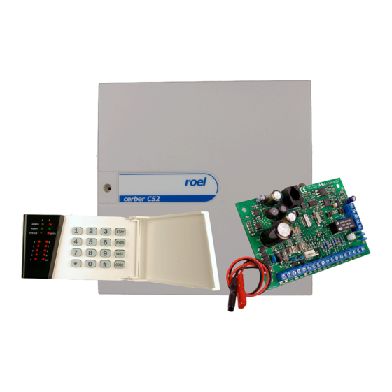
- Page 1 CERBER C52/C82 10/16-Zone LED Keypad Operated Alarm Control Panel Installation and Programming Manual March 2016/ version 3.0.
-
Page 2: Table Of Contents
Table of contents ........................4 1. INTRODUCTION General Features ............................. 4 User Codes ..............................4 Installer Codes ..............................4 Digital Communicator ............................4 Upload/Download ............................. 5 Zones ................................5 PGM functions ..............................6 Monitoring of system troubles ..........................6 Synthesis Sound Communicator ......................... 6 Miscellaneous .............................. - Page 3 Sections [01] … [10]/[16] (1 to 10/16 zones’ defining) ................... 31 Section [01] - Defining zone 1 ........................35 Section [02] - Defining zone 2 ........................35 Section [03] - Defining zone 3 ........................35 Section [04] - Defining zone 4 ........................35 Section [05] - Defining zone 5 ........................
-
Page 4: Introduction
1. INTRODUCTION ENERAL EATURES • Central unit's core of powerful RISC microprocessor; • The electrical features include an EEPROM memory for the programmed configuration, system/partitions status and LOG buffer to be retained even after a total power loss; • User-friendly programming of the system parameters, from keypad or by PC (using „EZcom C52/C82 Software”);... -
Page 5: Upload/Download
ONES • 5 fully programmable zones on the main board, expandable to 10 zones using zone doubling feature (Cerber C52) • 8 fully programmable zones on the main board, expandable to 16 zones using zone doubling feature (Cerber C82) •... -
Page 6: Pgm Functions
• 2 real partitions which can be armed/disarmed independently from each other – allowed by user rights; • Individually programmable exit and entry delay times for each partition – allowed by programming; • Programmable alarm type: silent or audible and for audible alarms steady or pulsing; •... -
Page 7: Technical Specifications
• 1 supervised siren output with positive trigger Current capability on +BELL: Cerber C52: up to 1A – fuse protected 1.25A Cerber C82: up to 2A – fuse-less design, automatic restore of BELL trouble Note: Current capability and protections for the auxiliary power supply (+AUX) and for the bell control output (+BELL) as well are valid only if the control panel is powered both from the AC power source (240Vac) and the backup battery, too. -
Page 8: Keypads
EYPAD TYPES The following keypads are available: KP-106P: has 10 zone and 6 status indicator lights; it is for use with CERBER C52 control panel KP-106L: has 10 zone and 6 status indicator lights; it is a larger and elegant format keypad and is for use with CERBER C52 control panel KP-164P: has 16 zone and 4 status indicator lights;... - Page 9 READY LED (KP-164P) a) While the entire system is armed – OFF. b) While at least one partition is disarmed or during the exit time: • ON – the system is ready for arming (all zone loops are closed even those which allow “forced arming”...
- Page 10 b) While the system / partition A is disarmed: • • ON – while the master user is being within master user’s menu of program/modify the user codes, “follow-me” phone numbers or system date and hour; • ON - while the installer is being within programming menu of the system parameters.
-
Page 11: Installing And Commissioning
3. INSTALLING AND COMMISSIONING OUNTING THE ANEL Select a dry location close to an unstitched AC source, allowing a ground connection. If the alarm system needs to be monitored by a “central station” or if it is intended to transmit synthesis sounds, the location must be also close to a telephone line. -
Page 12: Connectors
ONNECTORS The following connectors can be found on the panel PCB: AUX-, AUX+ Connectors for auxiliary power supply. These terminals are used to supply power to the keypads, PIR detectors and other active devices in the system, which require power from a 14.2Vcc supply source). The maximum load on these terminals should not exceed 1A. -
Page 13: Commissioning
Note: The picture above is an example of an outdoor siren connection (model SA 11) on CERBER C52/C82. If both internal and external sirens are used simultaneously, the 2K2 resistor should be mounted in the outdoor siren. CERBER C52 : Z1, Z2, COM, Z3, COM, Z4, Z5 CERBER C82 : Z1, Z2, COM, Z3, COM, Z4, Z5, COM, Z6, Z7, COM, Z8 Terminals for burglary zones;... -
Page 14: Operation
4. OPERATION KP106P KP106L KP164P KP166L The keypad is the device that helps with system programming, entering commands and data, as well as display of the system status. System operation is performed using the LED indications on the front side of the keypad. The KP-106P and KP106L keypads have 10 Zone LEDs and 6 status LEDs: A &... -
Page 15: Installer's Code
ARTITIONING The CERBER C52/C82 has implemented the partitioning feature which can divide the alarm system into two distinct areas identified as partition A and partition B. Partitioning can be used in installations where shared security systems are more practical, such as home offices or warehouse buildings. -
Page 16: Other Arming Modes
- The user code is entered while the green READY LED is OFF; all zones which doesn’t allow „forced arming” feature must be closed when the system/partition is armed. - The user code is entered while the green READY LED is blinking but the code hasn’t the right of force arming;... -
Page 17: Instant Stay" Arming
allow „forced arming”. If this occurs, the control panel will report “fail to auto arm” code and the system/partition will not arm for a new inactivity time. The type of autoarming is “regular” or “stay” and is dependent on the appropriate options within [25] and/or [26] sections. -
Page 18: Stay Arming
In a partitioned system, in order to arm a partition in an „instant stay mode”, by users assigned to only one partition, simply key in a valid user code within one of the previous sequences; the corresponding partition will instant stay arm. In a partitioned system, in order to arm a partition in an „instant stay mode”, by users assigned to both partitions, simply key in a valid user code within one of the previous sequences;... -
Page 19: Switch To Stay Arming
In a partitioned system, in order to stay arm a partition, by users assigned to both partitions, simply key in a valid user code within one of the previous sequences; the zone 1 and 2 LEDs will flash for 7 second, allowing the user to choose the partition/partitions to be armed, by pressing [1] and/or [2] keys. -
Page 20: Other Operation Commands
[User Code] [x][x][x][x] In order to disarm an already armed system/partition or to deactivate an alarm the users should enter the protected area through any delayed zone and simply key in a valid user code (4 digits). Once a delayed zone is first violated during one arming period it will start the appropriate entry delay timer;... -
Page 21: System Trouble Displaying: [*][4] Command
OFF only after the system date and hour programming. (Power ON) Cerber C52: This trouble indicator will appear if wiring between the siren and the panel is cut-off or its fuse was burnt after applying an overload higher than 1.25A. It will turn OFF after the siren is re-connected or the fuse is replaced. -
Page 22: Alarm Memory Displaying
Zone LEDs DESCRIPTION DETAILS If at least one keypad or zone tamper is open this trouble Zone 7 LED “Tamper trouble” indicator will turn ON and it will turn OFF after all keypad or zone tampers are closed. The actual trouble beeps can be stopped by system/partition arming or by any entering within trouble displaying menu (by pressing the [*][4] Keys). -
Page 23: Next Trouble Beeps Or Chime Feature Activating / Deactivating
LED 4 indicates an alarm triggered from the keypad tamper. To return to visualization of the alarms triggered from zones, press [*] again. To exit the alarm memory displaying menu press [#] key. Remark: The alarm memory will be cleared every time the system/partition is armed. Note: In a partitioned system, after entering the [*][5] command, zone LEDs 1 and 2 will start blinking waiting for the user to choose which partition alarm memory he wants to display. -
Page 24: Programming / Selective Erasure (Except The „Master Code") Of 01 To 30 User Codes
1. Selective Programming / Erasure of 01 to 30 user codes („master user’s submenus” from [01] to [30]); 2. Simultaneous Erasure of all user codes, except the „master code” („master user’s submenu” [49]); 3. Selective Programming / Erasure of the follow me phone numbers („master user’s submenus”... - Page 25 While the system is within programming / erasing session of the „selected user code”, the keypad LEDs’ status will be as follows: Keypad LEDs: LEDs’ Status: Remarks: entering. Means the „selected user code” isn’t programmed and the control Only zone 1 LED Blinking panel is waiting for the first digit entering.
-
Page 26: Simultaneous Erasure Of All Users' Codes (Except The „Master Code")
5. Erasure of „selected user code” (except the „master code”) can be performed by entering of [*] key (instead of sequence of 4 digits) while the control panel just entered the programming/erasing session of the corresponding „selected user code”. The keypad buzzer will sound 6 confirmation beeps and the control panel will go back within „master user’s programming menu”. -
Page 27: Program The
2. In order to program the selected phone number, you should enter up to 15 digits as you would on a key phone. 2.1 The zone 1 and 2 LEDs will blink after first digit entering of a new sequence for selected phone number. -
Page 28: Erase The 4 Simultaneous Erasure Of All Follow Me Phone Numbers
IMULTANEOUS RASURE OF ALL OLLOW ME HONE UMBERS [*][7][Master Code][50] or [CODE][Master Code][50], where [CODE] is the key labeled “CODE” While the system is within „master user’s programming menu”, to simultaneous erase all follow me phone number, select the corresponding submenu [50. The keypad buzzer will sound 6 confirmation beeps and the control panel will go back into master user’s programming menu. -
Page 29: Cancellation Of The Sound Communication And The Upload/Download Process
Zone bypassing by “EZcom C52/C82 Software”; Mono-stable / bi-stable PGM outputs’ activation / deactivation by “EZcom”. Remark: CERBER C52/C82 control panel provides 2 communication methods to the PC: The control panel answers automatically to the upload/download calls after “double call” or after number of rings programmed in section [36]. -
Page 30: System Parameters' Programming
6. SYSTEM PARAMETERS’ PROGRAMMING order enter programming menu system parameters („main programming menu”), the installer should use the command [*][8][Installer’s programming code], while the system is totally disarmed. Notes: The default value of the installer’s programming code is „0269” and it should be changed before or after the system parameters were programmed. -
Page 31: Programming Sections
Within some submenus or programming sections, the specific data are as option or attribute types; the status of these options / attributes is display-able on 1 to 8 zone LEDs. In order to turn these options / attributes activate / deactivate, you should press [1] to [8] keys and the corresponding zone LEDs will turn ON / OFF. - Page 32 1.1 Set the type of the selected zone by entering a 2-digit group, according to the table bellow: ZONE TYPES: REMARKS: [00] not used zone These zone types are usually used for entry/exit detections. The zones can be violated during the exit delay without triggering the alarm. Once the system/partition is armed, first violation of these zones will start the appropriate entry-delay timer.
- Page 33 switches ON / OFF; if the zone LED is ON means the appropriate attribute is enabled and if the zone LED is OFF means the attribute is disabled. ATTRIBUTES ATTRIBUTES set: Remarks Zone LEDs The alarm triggered by a zone with this attribute set as „audible” type will occur with siren activating for a time lapse set in section [39].
- Page 34 After the ATTRIBUTES set for the selected zone was established to the required values, press [#] key to confirm. After [#] key was pressed, the keypad buzzer will sound 3 confirmation beeps and the panel will pass to the next step, displaying the ATTRIBUTES set on 1 to 5 Zone LEDs.
-
Page 35: Section [01] - Defining Zone 1
ATTRIBUTES set: Zone LEDs Remarks: 10/16, obtained by doubling the low zones), copy these attributes from the corresponding low zones; by default, these 2 and 3 attributes from the above set, are disabled for all zones. After establishing these 2 set of attributes for the selected zone, press [#] key to confirm. -
Page 36: Section [07] - Defining Zone 7
Do the same as for zone 1. [07] - D ECTION EFINING ZONE Do the same as for zone 1. [08] - D ECTION EFINING ZONE Do the same as for zone 1. [09] - D ECTION EFINING ZONE Do the same as for zone 1. [10] - D ECTION EFINING ZONE... -
Page 37: Set Of General System Options
[20] – 1 ECTION SET OF ENERAL YSTEM PTIONS While the system is within „main programming menu”, to establish the 1 set of General System Options select section [20]. Once the panel entered section [20] the keypad buzzer will sound 3 confirmation beeps and the panel will display the 1 set of General System Options, according to the table bellow: Keypad LEDs’... -
Page 38: Set Of General System Options
zone 4 LED enabled disabled case tamper of keypad 4 enabled disabled zone 5 LED tamper alarm activates siren when disarm enabled disabled zone 6 LED send periodical test only when armed zone 7 LED enabled disabled next trouble beeps stopping zone 8 LED enabled disabled... -
Page 39: Partition Options
Keypad LEDs’ status while the system is within displaying submenu set of 1 Partition Options zone 2 LED enabled disabled quick instant stay arming zone 3 LED enabled disabled quick stay arming zone 4 LED enabled disabled forced arming without codes dings (1 ding upon arming, 3 dings upon disarming and 6 dings zone 5 LED enabled... -
Page 40: Set Of General System Options (Telephone Options)
Keypad LEDs’ status while the system is within displaying submenu set of 1 Partition Options READY A LED READY B LED Zone LEDs zone 1 LED enabled disabled timed autoarming enabled disabled inactivity autoarming zone 2 LED zone 3 LED enabled disabled beep on exit delay... -
Page 41: Section [28] - 5 -Th Set Of General System Options (Digital Communicator)
ARMED A LED ARMED B LED SYSTEM LED Blinking READY A LED READY B LED Zone LEDs OPTION zone 1 LED pulse DTMF dialing mode zone 2 LED enabled disabled compatible with TBR21 standard while DTMF dialing zone 3 LED enabled disabled* enables prefix when DTMF dialing... -
Page 42: Section [29]: "Swinger Shutdown Counter" / "Keypad Lockout Counter
READY A LED READY B LED Zone LEDs OPTION zone 1 LED enabled* disabled Digital communicator zone 2 LED enabled* disabled Answer to PC calls zone 3 LED enabled disabled Answer to the interrogation calls zone 4 LED after double call after number of rings Answer mode to the remote calls zone 5 LED... -
Page 43: Section [31] - Exit Delay 1 / Exit Delay 2 Timers
|__|__|__||__|__|__| |030||030| by default The default entry delay times are both 30 seconds. After the first 3 digits, the keypad buzzer will sound 3 beeps and after the last 3 digits it will sound 6 beeps; the panel exits the section and will wait for a new command to enter another section. -
Page 44: Section [32] - Burglary / Fire Bell Cut-Off Timings
[32] – B ECTION URGLARY ELL CUT OFF TIMINGS These timings („burglary bell cut-off timing” and „fire bell cut-off timing”) establish „siren activation timings” in case of any “fire alarms” and audible “burglary alarms” respectively will occur in the system. While the panel is within the “main programming menu”, to program the Burglary / Fire Bell cut-off timings, select section [32] and enter 2 groups of 2 digits each (01 to 99 minutes). -
Page 45: Section [36] - Ring Number After That The Control Panel Answers To The Remote Calls
After the first 3 digits were entered, the keypad buzzer will sound 3 beeps and after the last 3 digits 6 beeps. Then the panel exits the section and will wait for a new command to enter another section. Press [#] key instead of the corresponding 3-digit group if one of the 2 timings isn’t to be modified. -
Page 46: Section [39] - Pgm1 And Pgm2 Type Programming
[39] - PGM1 PGM2 T ECTION ROGRAMMING The system has 2 programmable outputs on the main board: PGM1 and PGM2. These outputs are NPN transistors activated to the ground. While system is within „main programming menu”, to set the type of programmable outputs PGM1 and PGM2 select section [39] and then enter 2 groups of 2 digits each: |__|__|... -
Page 47: Section [40] To [45] - Event Reporting Codes In Contact Id Format
Whenever the system/partition is armed, the output goes to ground for the time programmed in section [35]. [0E] P ULSE ON DISARMING When the system is disarmed, the output goes to ground for the time programmed in section [35]. [0F] B STABLE The output changes from activated to deactivated and the other way round for each command [*][9]. -
Page 48: Section [44] - Event Reporting Regarding: "Partial Arming" / "Fail To Autoarm" / "Ac Power Failure" / "Battery Failure" / "Bell Trouble" / "Auxiliary Supply Trouble" / "Time & Date Inaccurate
Timed Autoarming 34 [03] Inactivity Autoarming 34 [04] Quick Arming 34 [08] Quick Stay Arming 34 [08] Disarming By PC Software 14 [07] Timed Auto Disarming 14 [03] [44] – E : “P ” / “F ” / “AC P ECTION VENT EPORTING REGARDING... -
Page 49: Section [48] - „Inactivity Time" After That The Partition B Will Auto Arm (Hour & Minute)
[48] – „I ” & ECTION NACTIVITY AFTER THAT THE ARTITION WILL HOUR MINUTE Enter 2 groups of 2 digits; the first 2 digits for the number of hours (00 to 99) and the second 2 digits for the number of minutes (00 to 99) after that the partition B will auto arm if no motion will be detected in the protected area. -
Page 50: Section [50] - Master Code Programming, Performed By Installer
No right is enabled for the installer’s code. The „installer’s code” erasing isn’t allowed. If, by mistake, one is trying to erase the installer’s code, by entering [*] key instead of the 4-digits code, the keypad buzzer will sound a long rejection beep and the panel will go back within “main programming menu”... -
Page 51: Section [51] - Activation Moment For Pgm1 As "Clock Timer" (Hour:minute)
Keypad LEDs’ status while the system is within displaying submenu of the master code rights: SYSTEM LED Blinking READY A LED READY B LED Zone LEDs zone 1 LED enabled disabled Zone bypassing zone 2 LED enabled disabled Regular arming zone 3 LED enabled disabled... -
Page 52: Section [53] - Activation Moment For Pgm2 As "Clock Timer" (Hour:minute)
Note: The PGM1 as “clock timer” will deactivate only if the entered data was valid; the value for hour [hh] is between 0 and 23 and the value for minute [mm] is between 0 and 59. [53] – A PGM2 “C ”... -
Page 53: Section [57] - Auto Arming Moment For Partition B (Hour:minute)
Note: the system / partition A will auto disarm only if the appropriate option was enabled by programming and if the entered data was valid (the value for hour [hh] is between 0 and 23 and the value for minute [mm] is between 0 and 59). -
Page 54: Section [61] - First Phone Number For Cs Reporting
Note: the control panel will use the second panel account in order to identify the partition B to CS. [61] - F ECTION IRST HONE UMBER FOR REPORTING This is the phone number which panel will dial first to communicate the reporting events occurred within system / partition A;... -
Page 55: Section [63] - Panel Identification Code Upon Upload/Download
2. In order to program the selected CS phone number, you should enter up to 15 digits as you would on a key phone. 2.1 The zone 1 and 2 LEDs will blink after first digit entering of a new sequence for selected CS phone number. -
Page 56: Section [66] - Cancellation Of Phone Communication
CERBER C52 Control Panel CERBER C82 Control Panel Note: To avoid damaging the modem, connect a 100 ohms resistor between AUX+ and TIP terminal as shown above [66] - C ECTION ANCELLATION OF HONE OMMUNICATION [*][8][Installer Code][66] Command allows installer... -
Page 57: Warning Limitations Of Alarm Systems
ARNING IMITATIONS OF LARM YSTEMS Although of an advanced design, this security system does not offer 100% guarantee of warning or assured protection against burglary, fire or other emergency. Any alarm system, whether commercial or residential, is subject to compromise or failure to warn for a variety of reasons. For example: •... -
Page 58: Technical Specifications
+AUX maximum current (Cerber C82) 2.5A – fuse-less +BELL maximum current (Cerber C82) 2.5A – fuse-less Note: For Cerber C52 control panels, use the indicated rate fuses, or the control panel’s board may be damaged by short-circuits on +AUX and/or +BELL outputs. - Page 59 APPENDIX A: C52/C82 CONTROL PANEL RESPONSE ACCORDING TO THE ZONE WIRING TYPES A.1. SINGLE ZONE INPUT TERMINAL CONNECTIONS The system hardware recognizes the following single zone input terminal connections. For more information on programming the options mentioned in the following sections refer to the zone definitions within 01 to 10 programming sections.
- Page 60 If your security installation does not require tamper or wire fault recognition, connect the detection devices as shown in the next figure and ensure the zone wiring attributes are programmed as shown in the next table. This setup will communicate the violated zones to the control panel which will display them on the keypads. Do not use devices with N.O.
- Page 61 APPENDIX B: HANDLING of the “FIRE DETECTOR RESET” and “FIRE LOOP SUPERVISION” by the CONTROL PANEL CERBER C52 & C82 v1.2 A new PGM type has been added – “FIRE DETECTOR POWER SUPPLY”; it can be programmed within [39] section as hexadecimal value 12, for any of the 2 PGMs.
- Page 62 use always only fire detectors with NC contact output, connect the sensors’ contacts each one in parallel with appropriate zone resistor and then in series, with respect to the above wiring diagram; General notes: program the PGM output as “FIRE DETECTOR POWER SUPPLY” (12 HEX value) within [39] section, to reset the fire detectors;...
Need help?
Do you have a question about the CERBER C52 and is the answer not in the manual?
Questions and answers