Table of Contents
Advertisement
Quick Links
Advertisement
Table of Contents
Troubleshooting

Related Manuals for Magnum Dimensions ME-AGS-N

Summary of Contents for Magnum Dimensions ME-AGS-N
- Page 1 ME-AGS-N Automatic Generator Start for Network Versions Owner’s Manual Version...
- Page 2 ME-AGS-N can reasonably be expected to cause the failure of that life-support device or system, or to affect the safety or effectiveness of that device or system. If the ME-AGS-N fails, it is reasonable to assume that the health of the user or other persons may be endangered.
- Page 3 Product Safety Information IMPORTANT PRODUCT SAFETY INSTRUCTIONS This manual contains safety instructions that must be followed during the installation and operation of this product. Read all instructions and safety information contained in this manual before proceeding. Safety Symbols To reduce the risk of electrical shock, re, or other safety hazard, the following safety symbols have been placed throughout this manual to indicate dangerous and important safety instructions.
- Page 4 Product Safety Information WARNING: With an AGS system installed, exhaust CO, electrical shock, and moving parts hazards are possible due to unexpected engine/generator starting. Disconnect the engine/generator starting battery cables or AGS connection to the engine/generator before working on the generator or any other electrical system powered by it.
-
Page 5: Table Of Contents
Table of Contents Introduction .............1 AGS-N System Requirements ........2 AGS-N Components ..........2 ME-AGS-N Features ..........3 Installation ..............4 Installation Requirements .......... 4 Required Materials/Tools (not included) ....... 6 Mounting Procedure ..........6 Connecting the Supplied Cables to the AGS-N ....7 2.4.1... - Page 6 List of Figures Figure 1-1, Components of the AGS-N Controller ....... 3 Figure 2-1, AGS-N System Diagram ......... 5 Figure 2-2, AGS-N Dimensions ..........6 Figure 2-3, Remote Temp Sensor Connection ......7 Figure 2-4, Network Communication Cable ........ 7 Figure 2-5, Connecting an AGS to an Inverter (Small) ....
-
Page 7: Introduction
Introduction Introduction Congratulations on purchasing the ME-AGS-N. This is the ‘network’ version of a Magnum Automatic Generator Start (AGS) controller, and is set up/operated via a Magnum inverter and remote control (e.g., ME-RC, ME-ARC, or ME-RTR). Info: If you need an AGS, but are not using a Magnum inverter/ charger, use the ME-AGS-S (AGS –... -
Page 8: Ags-N System Requirements
AGS-N. The inverter must also have the internal software to work with the remote and to allow the desired AGS features. AGS-N Components The ME-AGS-N is shipped with the following: • ME-AGS-N controller • 10’ Network comm cable • 60’ Remote temp sensor cable • #8 x ¾”mounting screws (x4) •... -
Page 9: Me-Ags-N Features
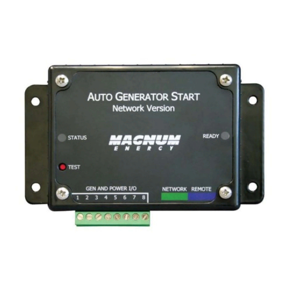
Introduction ME-AGS-N Features The AGS module provides the generator’s wiring connections and the following components (refer to Figure 1-1): STATUS Indicator: a bi-color (green or red) LED indicator that illuminates to provide information on the AGS’s operation. TEST Button: a momentary pushbutton that allows the AGS system to be tested for correct wiring and generator start/stop operation. -
Page 10: Installation
Installation Installation Installing the AGS is a simple process. Before installing, review the Important Product Safety Instructions on page ii of this manual and read the section below to ensure the overall system requirements are met. To assist you in planning and designing your installation, review the basic system diagram shown in Figure 2-1. -
Page 11: Figure 2-1, Ags-N System Diagram
O N/O F F IN V E R T ER S H O R E A G S ME T ER S ET U P T EC H ME-AGS-N Magnum inverter Battery voltage (12v/24v/48v) Monitored Battery Bank* Battery bank’s negative and generator * Normally the inverter’s... -
Page 12: Required Materials/Tools (Not Included)
Installation Required Materials/Tools (not included) To properly install the AGS, you need to supply the following: Required Materials • #16 to #12 AWG (1.31 to 3.31 mm ) wire for connecting the AGS to the generator start/stop circuit and to the battery bank •... -
Page 13: Connecting The Supplied Cables To The Ags-N
If you are not using the temperature autostart feature, the temp sensor cable does not need to be connected. Note: The AGS’s READY light ashes if the temp sensor cable is not connected—this is normal. ME-AGS-N 60' Remote Temp Sensor cable Figure 2-3, Remote Temp Sensor Connection 2.4.2 Network Communications Cable... -
Page 14: Connecting The Ags-N To An Inverter
Phone Splitter Connects AGS network cable (from AGS’s green NETWORK port) and remote cable to inverter’s REMOTE (blue) port ME-AGS-N Remote Figure 2-5, Connecting an AGS to an Inverter (Small) • Large inverter (ME, RD, MS, MSH, MS-PE, MS-PAE Series) –... -
Page 15: Cable Connections With Multiple Devices
• Daisy Chain Confi guration – Network devices are linked in a series (Figure 2-8). If using this con guration, the ME-AGS-N must be the rst device connected to the inverter’s Magnum Net or Network port—followed by the second network device. -
Page 16: Connecting The Ags-N To A Generator
Installation 2.5.1.1 Negative Connections When connecting devices together (via a network communications cable), the return path (i.e., battery negative) of each battery powered device must be at the same potential (i.e., electrically common with each other—see Figure 2-9). This prevents a high- impedance path developing between the connected devices, which can cause the network cable to become the DC return path to the battery—possibly resulting in permanent damage to all connected... -
Page 17: Power Connections (Terminals 3 & 4)
This causes the inverter to begin charging, which in turn communicates to the AGS (via the network cable) that the generator is running—preventing another starter crank. * Requires ME-AGS-N with Rev 5.2 to use 2-Wire Standby mode. © 2016 Sensata Technologies... - Page 18 Installation • Gen Type is not 2-Wire Standby Mode – For all other Gen Type settings (other than 2-Wire Standby mode), the generator run sense must be 10 to 40 VDC—only while the generator is running. The gen run sense voltage from the generator is connected to Terminal 2 (positive) and Terminal 4 (negative) on the green 8-port terminal block on the AGS;...
-
Page 19: Figure 2-10, Generator Run Sense Options
Installation What if my generator does not have a gen run sense output? Review the alternative options (Figure 2-10) to provide this gen run sense voltage to the AGS. Option 1 – Tap into the positive side of the generator’s hour meter or running light;... -
Page 20: Gen Start/Stop Connections (Terminals 1, 5, 6, 7, & 8)
Installation 2.6.3 Gen Start/Stop Connections (Terminals 1, 5, 6, 7, & 8) This section covers the control relays inside the AGS controller, and provides information about wiring these relays to the generator’s start/stop circuit. You must identify the generator’s start and stop wiring requirements in order to determine: how many relays you require, the number of wires you connect, and in what combination. -
Page 21: Common Generator Wiring Diagrams
Installation The connection points to each relay are as shown (see Figure 2-11): Relays Inside the AGS controller 2 3 4 5 6 7 8 Normally Open (N.O.) contact on Relay 3 (RY3) Normally Open (N.O.) contact on Relay 2 (RY2) Common (COM) contact on Relay 1 (RY1) and Relay 2 (RY2) Normally Open (N.O.) -
Page 22: Warning Label
Installation Two-wire control generator types: These generator types integrate the control circuits for start-up, running, and stopping (Figure 2-13). The generator starts and runs when two control wires are connected, and then stops when they are disconnected. Three-wire momentary control generator types: These... -
Page 23: Figure 2-13, Two-Wire Control
Installation Input DC Voltage Jumper - set to monitored battery bank voltage (on 24V setting) Gen Type (2-Wire INS IDE Maintain Mode) Connected via communication cable to inverter’s Network port Inside Generator fuse Run / Off Switch fuse fuse 0 1 2 3 Monitored battery bank Ground... -
Page 24: Figure 2-14, Three-Wire Momentary Control
Installation Input DC Voltage Jumper - set to monitored battery bank voltage (on 24V setting) Gen Type (3-Wire Mode) INS IDE Connected via communication cable to inverter’s Network port Inside Generator fuse fuse STOP fuse START Monitored battery bank 0 1 2 3 (12V/24V/48V) Battery Hour Meter... -
Page 25: Figure 2-15, Three-Wire Maintain Control
Installation Input DC Voltage Jumper - set to monitored battery bank voltage (on 24V setting) Gen Type (Portable INS IDE Mode) Connected via communication cable to inverter’s Network port Inside Generator fuse fuse Switch fuse Monitored 30 50 19 battery bank 0 1 2 3 (12V/24V/48V) Battery... -
Page 26: Figure 2-16, Three-Wire Momentary Control (With Preheat)
Installation Input DC Voltage Jumper - set to monitored battery bank voltage (on 24V setting) Gen Type (5-Wire INSIDE Mode) Connected via communication cable to inverter’s Network port fuse Inside Generator PREHEAT fuse fuse STOP fuse START Monitored battery bank 0 1 2 3 (12V/24V/48V) Battery... -
Page 27: Ags-N Controller Setup
Setup N Controller Setup This section covers con guring the AGS’s internal settings. Confi guring the Internal AGS N Settings Remove the AGS controller’s four top screws and detach the plastic cover to access the Input DC Voltage Jumper and the 4-position DIP (Dual In-line Package) switch (Figure 3-1). -
Page 28: Table 3-1, Gen Type Settings
Terminal #2). Mode* 10 sec. (N.O.) 14 sec. GEN RUN PD. (N.O.) 4 sec. (N.O.) 25 sec. 5-Wire Generators: BTDA / BEG (Westerbeke), 205-DS (Martin Diesel), NL-673 Mode (Northern Lights). * ME-AGS-N Revision 5.2 or higher required © 2016 Sensata Technologies... -
Page 29: Ags-N Functional Operation
Operation N Functional Operation After all electrical connections to the AGS, batteries, and generator have been completed (prior to reconnecting the terminal block), perform the following tests to verify that the AGS system is functioning properly and the wiring from the AGS to the generator is correct. -
Page 30: Ags-N Controller Led Indicators
Operation The generator should run for approximately 30-60 seconds before automatically turning off (ensure it does not try to restart within the next two minutes). Note: If the generator attempts to start but does not run, continue to wait, the AGS will attempt to start the generator 3 more times. If your AGS/generator system passes all steps (may attempt an autostart x4), then the wiring from the AGS to the generator is correct. -
Page 31: Ags-N Controller Troubleshooting
(see functional operation tests in Section 4.0). If the generator does not start and stop as expected, refer to Table 5-1 below. WARNING: To be safe, unplug the green 8-port terminal block from the ME-AGS-N before performing maintenance on the electrical or generator system. Table 5-1, AGS... -
Page 32: Generator Starting/Running Troubleshooting
Troubleshooting Generator Starting/Running Troubleshooting This section helps troubleshoot the generator system when the AGS’s STATUS LED illuminates solid red (fault condition), or the remote control displays a generator autostart fault. • Press the TEST button on the AGS controller, or start the generator from your remote control. - Page 33 Troubleshooting • Gen Type is 2-Wire Standby Mode – When using 2-Wire Standby mode, the gen run sense signal is communicated from the remote control to the AGS through the remote control cable. The AGS determines that the generator is running when the remote communicates that it is in a charge state (e.g., Charging, Bulk Charge, Absorb Charge).
- Page 34 Troubleshooting 2. Ensure the negative terminal of the monitored battery bank* is in common/connected with the negative side of the generator battery. This ensures that the positive battery voltage (to Terminal 3) and the positive generator run sense voltage from the generator (to Terminal 2) have a common negative reference (to Terminal 4), and are correctly sensed/measured by the AGS.
-
Page 35: Appendix
Appendix Appendix Other Accessories and Equipment Sensata offers a number of devices and accessories that can be used to expand and enhance your AGS and inverter/charger system. 6.1.1 Optional Accessories for the AGS-N AGS Pigtail Adapters Sensata Technologies offers two pigtail adapters for use with the AGS. -
Page 36: Limited Warranty
Note: The normal one-year warranty is extended to ve years if the ME-AGS-N is ordered with and installed on one of our MP or MMP panel systems. To be eligible, a proof-of-purchase is required at the time of repair/service showing both were purchased at the same time. -
Page 37: How To Receive Repair Service
Warranty & Service Information How to Receive Repair Service If your product requires warranty service or repair, contact: • Sensata Technologies (Magnum Energy-branded products) at: Telephone: 425.353.8833 Fax: 425.353.8390 Email: MagnumWarranty@Sensata.com If returning your product directly to Sensata for repair, you must: 1. - Page 38 Magnum-Dimensions Products Manufactured by: Sensata Technologies 2211 West Casino Rd. Everett, WA 98204 Phone: 425.353.8833 Fax: 425.353.8390 Web: www.Magnum-Dimensions.com PN: 64-0039 Rev. B (ME-AGS-N Owner’s Manual)
Need help?
Do you have a question about the ME-AGS-N and is the answer not in the manual?
Questions and answers