Table of Contents
Advertisement
Advertisement
Table of Contents
Troubleshooting

Summary of Contents for Stingl SR–500
- Page 1 Instructional Manual Model SR–500 Rev.1.10 Model SR–500PS Rev. 2.00 (Safety Vacuum Release System) Version 3.4 Stingl Products PMB #325, 21010 Southbank Street Sterling, VA 20165 Tel (571) 434.6010; (888) 749-5433 Fax (571) 434-6013 www.stingl-switch.com U.S. Patent No. 6,059,536/6,342,841...
-
Page 2: Table Of Contents
Table of Contents Section Page INTRODUCTION...............2 IMPORTANT INFORMATION..........3 INSTALLATION................ 4 OPERATING INSTRUCTIONS..........16 TROUBLESHOOTING CALIBRATION ISSUES (SR500)........23 CALIBRATION ISSUES (SR500PS)........34 ERROR CODES..............39 CALIBRATION INSTRUCTIONS SR500......27 OPTIONAL EQUIPMENT............43 PARTS LIST................43 CONTACT INFORMATION.............44... -
Page 3: Introduction
The Stingl-Switch Model SR-500 is designed to be easily retrofitted on all existing pools, hot tubs, and spas, and is easily installed during new pool and spa... -
Page 5: Installation
Use ANSI/ASME A112-19.8 approved Drain Covers To prevent hair entrapment we STRONGLY recommend that you use Anti-Entrapment drain covers that meet ANSI/ASME A112-19.8 standards. Anti-Entrapment drain covers are only effective to a specific flow rate. To be sure you are not exceeding the flow rate stamped on the cover, please contact your pool builder or pool service professional. - Page 6 Pre-Installation Checklist ❑ 1. All Ports (drains, skimmers, vacuum lines, etc.) MUST BE FREE OF DEBRIS PRIOR TO INSTALLATION. Clogged ports will disrupt the normal vacuum level. ❑ 2. Backwash or otherwise clean filter as per manufacturer specification. ❑ 3. Clean pump trap basket and skimmer basket(s). ❑...
- Page 7 Switch Installation Mounting 1. Mount the SR-500 in a suitable location within 8 feet of the pump. 2. Before mounting, remove SR-500 from its plastic enclosure by depressing tab in upper left and pulling top portion of SR-500. Slide SR-500 out from the top. At this point, record the serial number of your SR-500 on the warranty card.
- Page 8 Wiring the SR500/SR500PS NOTE: THE STINGL-SWITCH CANNOT BE USED/RELIED ON AS AN ELEC- TRICAL DISCONNECT MEANS. A SEPARATE DISCONNECT MEANS MUST BE PROVIDED. A CERTIFIED ELECTRICIAN IN ACCORDANCE WITH THE NATIONAL ELECTRICAL CODE MUST COMPLETE ALL ELECTRICAL WORK. The voltage selector switch on the right side of the metal case MUST BE SET to match the incoming power.
-
Page 17: Operating Instructions
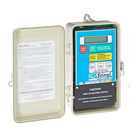
OPERATING INSTRUCTIONS Front Panel The SR-500 front panel features a two-line by 16-character backlit liquid crystal display and six momentary pushbutton switches implemented in a membrane label. Switches OFF/STOP – Immediately stops pump operation. Also silences any active alarms. ON/RUN – Toggles between timed, continuous run, and remote modes. MAINT/CLEAN –... - Page 18 Getting Started IMPORTANT! Before AC power is applied to the SR-500, the plumbing connection must be made properly. At the time of installation, or whenever the plumbing has been reconfigured or changed in any way, the unit will need to perform vacuum level measurements.
- Page 19 Wiring NOTE – THE SR500 CANNOT BE USED/RELIED UPON AS A SERVICE DISS- CONNECT MEANS. A SEPARATE DISCONNECT MEANS (SUCH AS A CIR- CUIT BREAKER) MUST BE PROVIDED. A CERTIFIED ELECTRICIAN IN ACCORDANCE WITH THE NATIONAL ELECTRICAL CODE MUST COM- PLETE ALL ELECTRICAL WORK.
- Page 20 For pumps over 3 Hp/20 amps, or for 3 phase pumps 1. Pump voltage must be carried by an external contactor rated for the pump load. Coil voltage can be either 120 or 240 volts, however, the coil voltage must match the out- put voltage of the SR500.
-
Page 21: Troubleshooting
By pressing and HOLDING the SET button for 5 seconds, Service Mode can be accessed and the SR500 can be calibrated. Wait until the screen changes from: SET UP MODE - SERVICE MODE - RELEASE FOR NEXT TECHNICIAN ONLY FIRMWARE VERSION Then release the SET button. - Page 22 is complete, prime the pump by filling the trap with water, insure that all valves are set for nor- mal operational, and clean the filter and all baskets. When the system is ready to operate, push the YES button to start the pump, and the screen will read: FULL PRIME? Y/N? RUNNING XX.XX “Hg and the current running vacuum level is displayed.
- Page 23 This is the upper vacuum threshold, or how much of a vacuum spike will register as an alarm. The factory default setting is 3” above the running reference, this should not be changed without factory consultation. Press the SET button to continue. Screen will read: HEATER DELAY? Y/N NO enable the heater delay circuit here by pressing the YES button.
- Page 24 TROUBLESHOOTING CALIBRATION ISSUES This message indicates that the sensor was not CANNOT SET ZERO! able to calibrate within 1” of zero. The hose SET TO CONTINUE MUST be disconnected from the sensor in order for the sensor to properly zero. A reading of 20 to 30 psi while trying to zero the sensor is usually indicative of water in the sensor body.
- Page 25 30 second three times and Give Error 11. This can be caused by a hydraulic condi- tion or inaccurate data in the SR500 memory. These cases are rare but can happen, especial- ly in suction lift systems. In these cases Stingl Products recommends contacting our Technical Department for further assistance.
- Page 28 CALIBRATION INSTRUCTIONS FOR SR500 POOL/SPA COMBINATION UNIT REV. 2.00 1. Before mounting, remove the SR500 from it’s plastic enclosure by depressing the tab in upper left and pulling the top of the unit forward. Slide the SR500 out toward the top. At this point, record the serial number of your SR500 on the warranty card.
- Page 29 2. Wire pump leads to Load 1 and Load 2. (#9 and #11) 120 VOLT INSTALLATIONS MUST USE BOTH LOADS CONNECTED TO BOTH TERMINALS OF THE MOTOR. 3. Connect panel and motor grounds to the green ground pigtail with a wire nut. Refer to Drawing 1 or 2 For pumps over 3 Hp/20 amps, or for 3 phase pumps 1.
-
Page 30: Service Mode
By pressing and HOLDING the SET button for 5 seconds, Service Mode can be accessed and the SR500 can be calibrated. Wait until the screen changes from: SET UP MODE - SERVICE MODE - RELEASE FOR NEXT TECHNICIAN ONLY FIRMWARE VERSION Then release the SET button. - Page 31 Now you are ready to run the pump and establish a set of reference values. Before this can be done, the hose must be hooked from the sensor in the SR500 to the drain port of the pump’s Hair and Lint Trap. FIRST, feed the hose through the hose fitting in the box and GENTLY slide the hose onto the sensor until it is against the top of the sensor fitting.
- Page 32 If spa mode is enabled in the service menu. If a VALVES SET FOR SPA? pool only setup, the unit will skip to vacuum cut- Y/N YES = START PUMP off. Press the YES button, and screen will read: Press the YES button again to start the pump, after PLEASE WAIT...
- Page 35 TROUBLESHOOTING CALIBRATION ISSUES This message indicates that the sensor was not CANNOT SET ZERO! able to calibrate within 1” of zero. The hose SET TO CONTINUE MUST be disconnected from the sensor in order for the sensor to properly zero. A reading of 20 to 30 psi while trying to zero the sensor is usually indicative of water in the sensor body.
- Page 36 Set-Up Mode for Revision 1.10 and Revision 2.00 P/S Combo Enter the SET-UP MODE by pressing the SET button when the unit is in the OFF MODE. As soon as the SET button is pressed, ** SET-UP MODE ** you will see this message in the display. Release RELEASE FOR NEXT the SET button to continue.
- Page 37 SET DATE - YEAR: The next selection in the SET DATE (-/+) SET-UP MODE is the year. The unit defaults to YEAR (00-99) 05 05, for 2005. To change the year, press the (-) and (+) buttons. Holding the buttons will make the value change faster. Once the desired year value is selected, press the SET button to save it and skip to the next function.
- Page 38 button again selects the REMOTE MODE, allowing the unit to be run by an external controller. In the TIMED MODE, the display shows the TIMED 12:00 PM current clock time, the pump status, and the PMP OFF 2.3 “Hg current vacuum or pressure level. When the pump is scheduled to start, the display TIMED 12:00 PM...
- Page 39 Maintenance Mode With the unit in the OFF/STOP MODE, select the MAINTENANCE MODE MAINTENANCE MODE by pressing the ENDS IN 29:59 MAINT/CLEAN button. This mode is used while operating a manual vacuuming system, or during trouble shooting procedures. The pump will start immediately; the heater is shut off. The internal and external alarms will sound for one second on, three seconds off.
-
Page 40: Error Codes
NOTE: Stingl Products does not recommend testing the main drain with an influent valve, due to the possibility of eliminating variables such as spring- loaded hydrostatic valves, and leaking or collapsing lines. Covering the sump with a mat ensures that the entire line is tested from the sump to pump. - Page 41 Error 11 – Check Pump Relay Explanation of a REAL error 11 – the SR500 is equipped with 2 redundant relays that swap places every time the unit starts the pump or energizes a contactor coil. If one of the two relays fuses closed it would make it impossible to stop the pump, so a switching/checking program is employed to prevent this from occurring.
- Page 42 set operating vacuum window. Usually caused by either the filter becoming dirty over time and needing to be backwashed (decreases running vacuum) or conversely the unit was installed on a dirty filter which was later backwashed (increases running vacuum) or bas- kets need to be emptied (increases running vacuum) Virtually any changes to the system such as installing a new motor or pump or adding/removing plumbing will alter the running vacuum.
- Page 43 ADDITIONAL OPERATIONAL NOTES: To successfully execute the PRIME PUMP function, the following conditions must be met: 1. The minimum difference between vacuum measurements made when the pump is stopped and the pump is running must be greater than 0.5” Hg. 2.
-
Page 44: Optional Equipment
OPTIONAL EQUIPMENT Remote Alarm: A stack alarm device with an audible and visual alarm. Wired directly to the 24V remote terminal in the SR-500. Freeze Protection: For the pool or spa that remain open year round. A freeze protection device that engages the pump when temperatures drop to near freezing. PARTS LIST Part # Part Description... -
Page 45: Contact Information
CONTACT INFORMATION STINGL PRODUCTS LLC Mailing Address: PMB # 325 21010 Southbank Stree Sterling, VA 20165 Office Address: 1334-B Shepard Drive Sterling, VA 20164 Telephone: (571) 434-6010 Toll Free: (888) 749-5433 Fax: (571) 434-6013 www.stinglproducts.com...
Need help?
Do you have a question about the SR–500 and is the answer not in the manual?
Questions and answers