Table of Contents
Advertisement
Quick Links
- Carefully check your model before
each flight to ensure it is airworthy.
- Consider flying only in areas
dedicated to the use of
model helicopters.
- Check and inspect the flying
area to ensure it is clear of
people orbstacles.
- Rotor blades can rotate at very
high speeds! Be aware of the
danger they pose.
- Always keep the model at a
safe distance from other pilots
and spectators.
- Avoid maneuvers with trajectories
towards a crowd.
- Always maintain a safe distance
from the model.
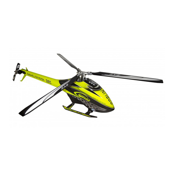
GOBLIN 380 KYLE STACY EDITION
SAB HELI DIVISION
SAB HELI DIVISION
Advertisement
Table of Contents

Related Manuals for Goblin 380 KYLE STACY EDITION


Summary of Contents for Goblin 380 KYLE STACY EDITION
- Page 1 GOBLIN 380 KYLE STACY EDITION - Carefully check your model before each flight to ensure it is airworthy. - Consider flying only in areas dedicated to the use of model helicopters. - Check and inspect the flying area to ensure it is clear of people orbstacles.
- Page 2 Release 1.0 - November 2015 WORLD DISTRIBUTION www.goblin-helicopter.com For sales inquiries, please email: sales@goblin-helicopter.com For information, please email: support@goblin-helicopter.com Attention: If you are a consumer and have questions or need of assistance, please contact the retailer where you made the purchased first.
-
Page 3: Very Important
To mount the serial number tag on your helicopter, please refer to page 7. Thank you for your purchase, we hope you enjoy your new Goblin helicopter! SAB Heli Division INDEX 1 –... -
Page 4: Important Notes
Chapter 2, Important Notes IMPORTANT NOTES *This radio controlled helicopter is not a toy. *This radio controlled helicopter can be very dangerous. *This radio controlled helicopter is a technically complex device which has to be built and handled very carefully. *This radio controlled helicopter must be built following these instructions. -
Page 5: Chapter 3, Components And Box
Chapter 3, Components and Box ADDITIONAL COMPONENTS REQUIRED TOOLS, LUBRICANTS, ADHESIVES *Electric Motor: 850 - 1000Kv: *Generic pliers. Maximum diameter 41mm. *Hexagonal driver, size 1.5,2,2.5mm. Maximum height 41mm. *5.5mm Socket wrench (for M3 nuts). Pinion shaft diameter 5 mm. *7mm Hex fork wrench (for M4 nuts). *Speed controller: minimum 60A , extreme 3D Flight 70-90A. -
Page 6: Carbon Frame
Chapter 4, Carbon Frame The manufacturing process of the carbon parts often leaves micro-burrs and sharp edges. We recommend de-burring the edges to minimize the 4-Carbon Frame risks of electrical wire cuts, etc. This is particularly important in the areas shown in red. Page 4... -
Page 7: Main Frame Assembly
Chapter 4, Carbon Frame Box 1, Bag 1 Left Main Frame Assembly Note: Main Frame Use Loctite 243 to (H0531-S) lock the bolts in the correct position. Tail Servo Support (H0530-S) Button Head Cap Plastic Battery Special M2.5x6mm Support (HC019-S) (H0529-S) SUGGESTION If you have the tail servo, we... - Page 8 Chapter 4, Carbon Frame Bag 1, Box 1 Lading Gear Assembly Socket Head Cap Screw M2.5x10mm (HC022-S) Plastic Landing Gear Support (H0556-S) Finishing Washer M2.5 (H0255-S) Alu Landing Gear Support (H0644-S) Socket Head Cap Screw M2.5x10mm (HC022-S) Main Frame Assembly Head Cap Screws Special M2.5x6mm (HC019-S)
-
Page 9: Chapter 5, Transmission Assembly
Chapter 5, Transmission Assembly Bag 2, Bag 19 Main Shaft Support Assembly Socket Head Cap Screw M2.5x8mm (HC020-S) Main Shaft Support (H0522-S) Main Shaft Assembly Bearing Ø8xØ16x5mm (HC419-S) Socket Head Cap Socket Head Cap Screw M2.5x8mm Screw M2.5x8mm (HC020-S) (HC020-S) Main Shaft Assembly Main Shaft Support Assembly... - Page 10 Chapter 5, Transmission Assembly Bag 3 Socket Head Cap Screw M2.5x18mm 120T Pulley Assembly (HC032-S) (H0502-S) One Way Bearing Ø8xØ12x12mm 120T Pulley (HC440-S) (H0502-S) Plastic Servo Support Flanged Bearing (H0548-S) Ø8xØ12x3,5 (HC418-S) Flanged Bearing Socket Head Cap Ø8xØ12x3,5mm Screw M2x5 (HC418-S) (HC002-S) Main Plate...
-
Page 11: Chapter 6, Main Rotor Assembly
Chapter 6, Main Rotor Assembly Bag 4 Note: Center Hub Assembly Blade Grip Linkage Assembly Flanged Bearing 2.5x 6x2.5 Center Hub (HC400-S) (H0595-S) Spindle Blade Grip Linkage (H0596-S) (H0598-S) Linkage Rod (H0561-S) Bushing [H0599] Head Cap Plastic Ball Link Screw M2.5x15mm (H0403-S) (HC028-S) HEX 2.5 Inside... -
Page 12: Chapter 7, Assembling The Modules
Chapter 7, Assembling The Modules Bag 5 Swashplate Assemly Metric Hex Nylon Nuts M3 (HC206-S) Uniball M2 Head Assembly (H0538-S) Socket Head Cap Shouldered M3x16mm (HC074-S) Swashplate Swashplate Assembly Uniball M2 Assemly Uniball M2 (H0538-S) (H0600-S) (H0537-S) Button Head Cap Special M2.5x6mm (HC019-S) Button Head Cap... -
Page 13: Chapter 8, Installation Of Swashplate Servos
The linkage ball must be positioned approximately 13-15 mm out on the servo arm (figure 1), it is recommended to use the SAB servo arm p/n [HA052]. Because of the 120° placement of the servos in the Goblin, the arms are difficult to access. For this reason it is advisable to ensure alignment of the servo arms (and sub trim) before installation of the servos in the model (figure 2). - Page 14 Chapter 8, Installation Of Swashplate Servos Tip on cable routing You can use zip-ties to secure the 3 servo cables to the servo support. HPS Head Preliminary Setup Linkage Rod A Assembly ... x2 Linkage Rod A Aseembly Approx 45mm Linkage Servo Linkage Rod M2x22mm (H0524-S)
-
Page 15: Chapter 9, Tail Servo Assembly
Chapter 9, Tail Servo Assembly Bag 6 Uniball M2 Socket Head Cap M3x6mm The distance between the servo spline (H0064-S) (HC044-S) and the ball must be between 13-15 mm You can use the SAB servo horn [HA053]. 14 mm Socket Head Cap M2x8mm (HC008-S) Tail Servo... -
Page 16: Chapter 10, Installation Of The Motor
H0501-21-S - 21T Pinion = ratio 5.7:1 H0501-24-S - 24T Pinion = ratio The Goblin 380 accepts a wide selection of batteries with different capacities. The suggested number of cells is 6. All batteries from 1500 to 2600 mAh offer good performance. - Page 17 Chapter 10, Installation Of The Motor Bag 7 NOTE: Correct position for the motor wires. Motor Pulley 21T (H0501-21-S) (see page 14 for optional pulleys) Cone Point Set Screws M3x6mm (HC144-S) Flat Head Socket Cap M3x5mm (HC132-S) Motor Support (H0520-S) Socket Head Cap Screws M2.5x8mm Finishing Washer M2.5...
-
Page 18: Motor Belt Tension
Chapter 10, Installation Of The Motor Bag 8 MOTOR BELT TENSION *Assemble the motor and pulley to its mounting plate. *Install the motor assembly in the helicopter. *It is easy to install the belt with the motor assembly pushed back towards the helicopter as far as it can go. First put the belt on the motor pulley. -
Page 19: Chapter 11, Installation Of The Esc
Chapter 11, Installation Of The ESC DE-BURR THE SIDE FRAMES We recommend de-burring the edges of the carbon parts in areas where electrical wires run.(See Page 4). ESC INSTALLATION The speed controller (ESC) is installed in the front of the helicopter. Figure 1 and Figure 2 show the mounting area. -
Page 20: Chapter 12, Installation Of Flybarless Unit And Rx
Chapter 12, Installation Of Flybarless Unit and RX Bag 9 FLYBARLESS CONTROL UNIT AND RX INSTALLATION We suggest the use of a “single unit” FBL system (all in one type unit). This allows for easier wire routing considering the small size of this helicopter. Position 1 can be used to install the FBL unit. - Page 21 Chapter 12, Installation Of Flybarless Unit and RX The area between the boom and the frame can be used to route the wire(s) (Fig 4 and 5). You can secure the wire(s) to the frame with zip-ties (Fig6). Page 19...
-
Page 22: Chapter 13, Tail Assembly
Chapter 13, Tail Assembly Bag 10 Tail Pitch Slider Assembly Tail Rotor Hub Assembly Tail Damper (H0567-S) eg: Microlube GL261 Tail Pitch Slider 03 (H0512-S) Tail Spindle Flanged Bearing (H0510-S) 11x3mm (HC416-S) Tail Pitch Slider 01 [H0231] Tail Shaft Flanged Bearing (H0509-S) Tail Pitch Slider 02 11x3mm... - Page 23 Chapter 13, Tail Assembly Bag 11 Tail Side Plate Assembly Bell Crank Lever Assembly Tail Side Cross Tail Case Alluminum Case (H0526-S) Flanged Bearing 2.5x 6x2.5mm (H0523-S) (HC400-S) Tail Pin (H0264-S) Spacer Arm 2.5x 4x6.3mm (H0253-S) Bell Crank Lever (H0234-S) Uniball 4 H3 (H0279-S)
-
Page 24: Tail Boom Assembly
Chapter 13, Tail Assembly Bag 12, Box 3 Note: We suggest to clean the sticking surface with sand paper. Locking Element Tail Assembly ..x 2 Tail Boom Assembly Locking Element Double Tail Assembly Sided Tape Locking Element Tail (H0535-S) (HA033-S) (H0535-S) Red Tail Boom... - Page 25 Chapter 13, Tail Assembly Bag 13 Socket Head Cap Screw M2.5x10mm (HC022-S) Finishing Washer M2.5 (H0255-S) Finishing Washer M2.5 (H0255-S) Socket Head Cap Tail System Screw M2.5x10mm Assembly (HC022-S) Note: Please allow plenty of time for the glue to cure before inserting plastic ball link onto the threaded rod. Threaded Rod Carbon Road Threaded Rod...
-
Page 26: Chapter 14, Installation Of The Boom, Canopy
Chapter 14, Installation Of The Boom, Canopy Bag 14 BOOM ASSEMBLY * Insert the boom. This operation is easier fitting into the main frame at a slight angle [Fig.1]. To facilitate boom insertion, you can also unscrew the two bolts that hold the tail servo support tray. * Tighten the M8 nut with HA016 special tool supplied. - Page 27 Chapter 14, Installation Of The Boom, Canopy Bag 15 TAIL BELT TENSION *Check for the proper assembly of the tail boom. *Loosen the tail case by loosening the 4 M2.5 screws. *Install the belt onto the front pulley in the correct direction of rotation (figure 1). *Rotate the tail drive several times by hand.
-
Page 28: Chapter 15, Battery
Bag 16 BATTERIES The Goblin has a quick release battery tray system. The batteries must be installed onto the battery tray to take advantage of the quick release locking system. Install the battery to the battery tray using double sided tape and the long Velcro straps included (Fig 1 and Fig 2). -
Page 29: Chapter 16, In Flight
*Be sure of the gear ratio, verifying carefully the motor pulley in use. The forces acting on the mechanics increase enormously at higher RPM. Although the Goblin can fly at very high RPMs, for safety reasons we suggest to not exceed 3400 RPM. -
Page 30: Maintenance
Chapter 17, Maintenance MAINTENANCE *On the Goblin 380, some areas to look for wear include: - Motor belt - Tail belt - Dampers *The most stressed bearings are definitely those on the tail shaft and the thrust bearings. Check them frequently. All other parts are not particularly subject to wear. - Page 31 Chapter 18, Exploded view, Carbon Frame Main Frame Name Specification Quantity H0255 Finishing Washers M2.5 Aluminum H0529 Plastic Battery Support Plastic H0530 Tail Servo Support Plastic H0531 Main Frame Carbon Fiber H0536 Battery Tray Support Carbon Fiber H0539 Battery Aluminum Block Aluminum H0556 Landing Gear Support Plastic...
-
Page 32: Chapter 18, Exploded View, Transmission Assembly
Chapter 18, Exploded view, Transmission Assembly TRANMISSION ASSEMBLY TRANMISSION ASSEMBLY Name Specification Quantity Name Specification Quantity H0255 Fnishing Washer M2.5 Aluminum 14 HC020 Socket Head Cap Screws M2.5x8mm H0501 21T Motor Pulley ASM Aluminum 15 HC031 Head Cap Screws Shouldered M2.5x15mm H0502 120T Main Pulley Aluminum 16 HC032 Socket Head Cap Screws... -
Page 33: Chapter 18, Exploded View, Head System
Chapter 18, Exploded view, Head System HEAD SYSTEM HEAD SYSTEM Name Specification POS COD Name Specification Quantity Quantity 13 H0600 Swashplate 01 Aluminum Washer 7,5x 10x0,5 H0349 H0403 Plastic Linkage Ball 14 HC020 Head Cap Screws M2.5 x 8mm H0513 Main Blade Grip Aluminum 15 HC028 Head Cap Screws... -
Page 34: Chapter 18, Exploded View, Tail System
Chapter 18, Exploded view, Tail System TAIL SYSTEM Name Specification Quantity H0065 Uniball M3 ø5 H6 H0066 Plastic Ball Link M2,5 TAIL SYSTEM H0076 Grip Link Bushing Brass Name Specification Quantity H0231 Tail Pitch Slider 01 Aluminum H0232 Tail Pitch Slider 02 Aluminum 25 H0566 Washer ø2ø4.5x0.5... -
Page 35: Chapter 19, Spare Parts
Chapter 19, Spare Parts Uniball M2 Uniball M3x4 Plastic Ball Link Bell Crank Lever [H0064-S] [H0065-S] [H0066-S] [H0234-S] - 1 x Bell Crank level. - 5 x Uniballs M2 5H6. - 2 x Tail Pin. - 5 x Uniball Spacers. - 2 x Flanged Bearing - 5 x Socket Head Cap Screws 2.5x... - Page 36 Chapter 19, Spare Parts Tail Spindle Tail Blade Grip Tail Pitch Slider [H0510-S] [H0511-S] [H0512-S] - 2 x Tail Blade Grip. - 2 x Thrust Bearing 6x2.5mm. - 2 x Bearing 7x3mm. - 2 x Bearing 6x2.5mm. - 1 x Tail Pitch Slider 01. - 2 x Washer 4.75x0.5mm.
- Page 37 Chapter 19, Spare Parts Uniball M2 Male Battery Block Tail Spacer KIT Canopy Nut (H0538-S) (H0539-S) (H0540-S) (H0542-S) - 2 x Washer 4.75x0.5. - 2 x Washer 4.5x 5.9x0.5. - 2 x Washer 4.5x0.5. - 1 x Battery Block. - 2 x Oring ID=2.9, S=1.78. - 2 x Canopy Nut.
-
Page 38: Standard Spare Parts
Chapter 19, Spare Parts Spindle Shaft Blade Grip Arm Linkage Swashplate [H0596-S] [H0597-S] [H0598-S] [H0600-S] - 1 x Linkages. - 1 x Linkage Rod. - 1 x Blade Grip Arm. - 1 x Bushing. - 1 x Swashplate Assembly. - 1 x Spindle Shaft. - 1 x Socket Head Cap - 2 x Flanged Bearings - 5 x UniBall M2... - Page 39 Chapter 19, Spare Parts [HC200-S] [HC206-S] [HC212-S] [HC224-S] [HC228-S] - 10 x Metrix Nylon - 10 x Metrix Nylon - 10 x Metrix Nylon - 4 x Metrix Nylon - 4 x Shim Nut M2.5. Nut M3. Nut M4. Nut M8. Ø8xØ14x0,2mm.
Need help?
Do you have a question about the 380 KYLE STACY EDITION and is the answer not in the manual?
Questions and answers