Air Lift AutoPilot V2 Installation Manual
Hide thumbs
Also See for AutoPilot V2:
- Installation manual (64 pages) ,
- Installation manual (29 pages) ,
- Installation manual (20 pages)
Table of Contents

Related Manuals for Air Lift AutoPilot V2


Summary of Contents for Air Lift AutoPilot V2
- Page 1 AutoPilot V2 ™ P A T E N T P E N D I N G INSTALLATION GUIDE For maximum effectiveness and safety, please read these instructions completely before proceeding with installation. Failure to read these instructions can result in an...
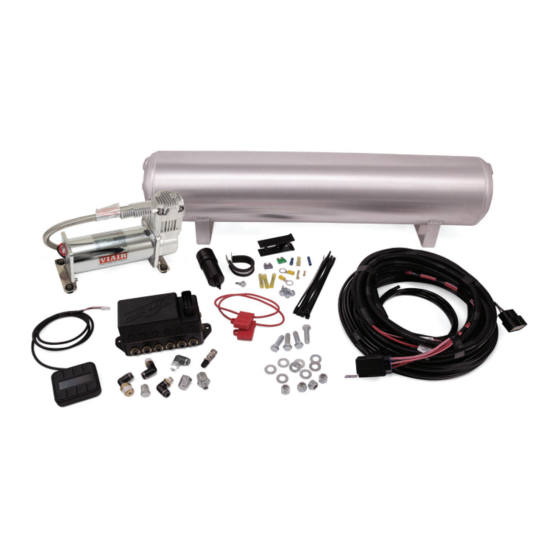
- Page 2 Air Lift Performance Kit Details 27671 HARDWARE LIST Part # Description ......Qty Part # Description 72605 4pt Fast Air Manifold - 1/4”....1 21999 1/8” MNPT X 1/4” PTC Elbow ..... 2 21633 Push Lock Valve ......... 1 27042 Gen 3 Display ........1 21585 1/4”...
- Page 3 The information includes step-by-step installation information, installation templates and a troubleshooting guide. Air Lift Company reserves the right to make changes and improvements to its products and publications at any time. For the latest version of this manual NOTATION EXPLANATION Hazard notations appear in various locations in this publication.
- Page 4 If the harness must be lengthened, use properly sized butt connectors and wire. If extending NOTE the power/ground wires, use 8AWG wire minimum or contact Air Lift for more information. The supplied harness is only capable of powering a single compressor. If installing dual compressors, a second dedicated power wire is required.
- Page 5 Air compressors intake moisture (humidity) from the outside air and will deposit water in the air NOTE tank. The AutoPilot V2 system includes a filter that will greatly reduce the potential for moisture to enter the manifold, however, tanks must be regularly purged to eliminate the possibility of water entering the manifold.
- Page 6 Route the 18AWG pink wire to a key switched IGNITION source that remains on during cranking. Examples include: ECU, fuel pump. Do not select an accessory source. If the AutoPilot V2 display shuts off while starting the NOTE vehicle, this is not a true ignition source.
- Page 7 8 different combinations of the 4 corner air spring pressures. After installing AutoPilot V2 in your vehicle, please follow the steps below to properly set up your new system. If changes are made after installing and calibrating the system such as changes to air springs, lines, tank, compressor, or other vehicle modifications, the system must be recalibrated to maintain accuracy.
- Page 8 Press button 2 to enter CALIBRATE (fig. 3). Press button 1 SYSTEM CAL (fig. 5), follow CALIBRATION MENU instructions to calibrate AutoPilot V2 system to your vehicle. Once calibration is complete, 1. SYSTEM CAL Press buttons (1+5) simultaneously to exit to 2.
- Page 9 6. COMP TIME the compressor and measure its inflate time 7. RISE ON START to achieve MAX pressure (fig. 9). AutoPilot V2 8. PSI/BAR & SWV will record this fill time, allowing the operator to compare future fill times to determine fig.
- Page 10 “Rear up”: for added load of PRESET 1 passengers, equipment. • “Play”: for those that want to enjoy their air suspension freedom, AutoPilot V2 fig. 13 has a special function that recognizes side-to-side presets. When left side EDIT pressures are equal, and right side pressures are equal but >25PSI...
- Page 11 Connect direct to battery Connect direct to battery Preferred Preferred Butt connector 30 AMP fuse NOTE: If not run to battery, voltage drop 30 AMP fuse Butt connector may reduce system performance and AL005 NOTE: If not run to battery, voltage drop durability.
- Page 12 NOTE: Air Lift recommends RIGHT RIGHT using a hose cutting tool to RIGHT RIGHT ensure a proper cut (Air Lift part number 10530). If a hose connection has been disconnected the hose must be For Reference Only For Reference Only...
- Page 13 Air Lift Performance Operating the System Now that your system is set up, it’s time to use it. If changes are made after installing and calibrating the system such as changes to air springs, lines, tank, or compressor, the system must be recalibrated to maintain system accuracy.
- Page 14 Air Lift Performance MANUAL Mode 1. MANUAL mode allows the user to fill or exhaust each spring independently. The display will show arrows above and below the pressures to indicate manual control mode (fig. 17). The arrow will be solid when the spring is filling/exhausting, and outlined when not active.
- Page 15 AUTOPILOT V2 GEN 3 PRESSURE CONTROL AUTOPILOT V2 SECOND COMPRESSOR HARNESS*...
- Page 16 Air Lift Performance AutoPilot V2 Remote Control Unit Dimensions 2.875” Top View .75” Side View MN-754...
- Page 17 Air Lift Performance Manifold Template IMPORTANT: PRINT THIS MANUAL AT 100% SCALE. THIS MANUAL CONTAINS A CAUTION DRILLING TEMPLATE, WHICH WOULD BE RENDERED INCORRECT IN DIMENSION IF PRINTED WITH ANY SCALING. USING AN INCORRECT TEMPLATE TO DRILL HOLES MAY CAUSE DAMAGE TO THE VEHICLE! PLEASE REFER TO THE ONE-INCH SCALE (FIG.
- Page 18 Air Lift Performance HOLE PATTERN FOR 16444 COMPRESSOR 8 1/2” 3 5/16” MN-754...
- Page 19 Air Lift Company, for all Air Lift Performance products, except its Air Lift Performance 3H™ and 3P™ systems, warrants to the original purchaser for a period of one year from the date of original purchase that the Air Lift Performance damper kits will be free from defects in workmanship and materials for the normal expected life of the part when used on cars and trucks as specified by Air Lift Company and under normal operating conditions, subject to the requirements and exclusions set forth below.
- Page 20 Air Lift Performance Replacement Part Information If replacement parts are needed, contact the local dealer or call Air Lift customer service. Most parts are immediately available and can be shipped the same day. Contact Air Lift Company customer service first if: •...
Need help?
Do you have a question about the AutoPilot V2 and is the answer not in the manual?
Questions and answers