
Related Manuals for Teltonika FM1000 ST


Summary of Contents for Teltonika FM1000 ST
- Page 1 FM1000 ST User Manual V2.9 *This version is suitable for device with universal FM1000 firmware v.00.10.XX.Rev.0 and later versions...
-
Page 2: Table Of Contents
Table of contents INTRODUCTION ........................6 1.1 A ..........................6 TTENTION 1.2 I ......................6 NSTRUCTIONS OF SAFETY 1.3 L ........................7 EGAL OTICE 1.4 A ......................... 7 BOUT DOCUMENT BASIC DESCRIPTION ....................... 7 2.1 P ........................ 7 ACKAGE CONTENTS 2.2 B ...................... - Page 3 5.12.1 Event Generating ....................43 5.12.2 Hysteresis ....................... 44 5.13 OBD ................... 44 FUNCTIONALITY DESCRIPTION 5.13.1 Supported OBD protocols ..................44 5.13.2 Data ........................44 5.14 A ........................46 CCELEROMETER SMS COMMAND LIST ......................47 6.1 SMS ......................47 COMMAND LIST 6.1.1 getstatus .........................
- Page 4 9.4.6 Backup Server Domain (ID=1241) ................60 9.4.7 Target Main Server Port (ID=1246) ................ 60 9.4.8 Target Backup Server Port (ID=1248) ..............60 9.4.9 Protocol (ID=1247) ....................61 9.4.10 Backup Server Protocol (ID=1249) ................61 9.4.11 SMS Login (ID=1252) ....................61 9.4.12 SMS Password (ID=1253) ..................
- Page 5 9.6.12 Crash Detection (ID=1612)..................70 9.6.13 Crash Detection Duration (ID=1613) ..............71 9.6.14 Crash Detection Threshold (ID=1614) ..............71 9.6.15 Towing Detection (ID=1291) ................... 71 9.6.16 Towing Detection Activation Timeout (ID=1292) ..........71 9.6.17 Towing Detection Ignition check after event (ID=1295) ......... 71 9.6.18 Towing Detection Duration (ID=1296) ..............
-
Page 6: Introduction
FM1000 has USB interface; Please use cables provided with FM1000 device. Teltonika is not responsible for any harm caused by using wrong cables for PC <-> FM1000 connection. Warning! Do not use FM1000 device if it distracts driver or causes inconvenience due to OBD II placement. -
Page 7: Legal Notice
Legal Notice Copyright © 2015 Teltonika. All rights reserved. Reproduction, transfer, distribution or storage of part or all of the contents in this document in any form without the prior written permission of Teltonika is prohibited. Other products and company names mentioned here may be trademarks or trade names of their respective owners. -
Page 8: Basic Characteristics
Basic characteristics GSM / GPRS features: Teltonika TM11Q quad band module (GSM 850 / 900 / 1800 / 1900 MHz); GPRS class 10; SMS (text, data). GNSS features: TG3300 32 channel (or equivalent) receiver; Up to -161 dBm sensitivity. Hardware features: •... -
Page 9: Technical Features
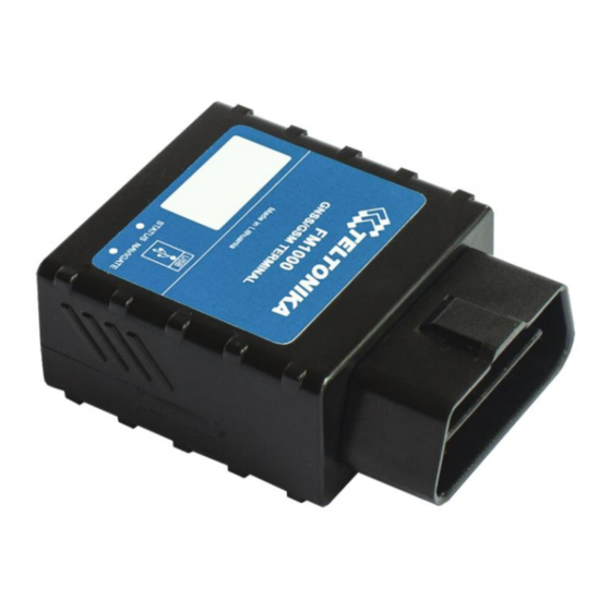
Technical features Part name Physical specification Technical details Power supply 10...16 V DC Navigation LED 2W Max Modem LED Energy consumption GPRS: average 105 mA r.m.s; GNSS Internal GNSS antenna Nominal: average 49 mA r.m.s; Internal GSM antenna GNSS Sleep: average 20 mA;... - Page 10 Figure 1 FM1000 view & dimensions (tolerance ±1 mm)
-
Page 11: Electrical Characteristics
Electrical characteristics VALUE Min. Typ. Max. Unit CHARACTERISTIC DESCRIPTION Supply Voltage: Supply Voltage (Recommended Operating Conditions) Digital Input: Input resistance (Ignition) kΩ Input Voltage (Recommended Operating Supply Conditions) voltage Input Voltage threshold (Ignition) Absolute Maximum Ratings VALUE Min. Typ. Max. Unit CHARACTERISTIC DESCRIPTION Supply Voltage (Absolute Maximum Ratings) -
Page 12: Connection, Pinout
3 CONNECTION, PINOUT How to insert SIM card into FM1000 device: Gently open FM1000 case using screwdrivers Remove FM1000 case Insert SIM card as shown... -
Page 13: Installing Fm1000 Drivers
Software requirements: • Operating system 32-bit and 64-bit: Windows XP with SP3 or later, Windows Vista, Windows 7, Windows 8. • MS .NET Framework V3.5 or later (http://www.microsoft.com or http://avl1.teltonika.lt/downloads/tavl/Framework/dotnetfx35setupSP1.zip). Drivers: Please download Virtual COM Port drivers from Teltonika website: http://avl1.teltonika.lt/downloads/FM1000/vcpdriver_v1.3.1_setup.zip... - Page 14 Installing drivers: Extract and run VCPDriver_V1.3.1_Setup.exe. This driver is used to detect FM1000 device connected to the computer. Click 'Next' in driver installation window (figures below): Figure 2 Driver installation window This will launch device driver installation wizard. In the following window click ‘Next’ button again: Figure 3 Driver installation window...
-
Page 15: Navigate Led
Setup will continue installing drivers and will display a window about successful process at the end. Click 'Finish' to complete setup: Figure 4 Driver installation window You have now installed drivers for FM1000 device successfully. Navigate LED Behavior Meaning Permanently switched on GNSS signal is not received Blinking every second Normal mode, GNSS is working... -
Page 16: Usb
GND (-) Ground pin CAN H K-Line PWM BUS- CAN L L-Line Power range +(10...16) V DC to ground Power +(1016) V DC Table 2 OBD II pinout description Figure 5 OBD II pinout Mini USB connector Figure 6 Mini USB type B connector FM1000 connected to PC creates an STM Virtual COM Port, which can be used as a system port (to flash firmware and configure the device):... -
Page 17: Firmware
Figure 7 COM-Ports 4 FIRMWARE Updating firmware using USB cable FM1000 functionality is always improving, new firmware versions are developed. Current module firmware version can be retrieved from Configurator. Connect FM1000 to PC with the USB cable. Launch “Firmware Updater”, select COM port to which device is connected, click connect, and when IMEI and Firmware version fields are filled, start the update. - Page 18 Figure 8. FM1000 firmware updater screen Figure 9. Firmware updating processes...
-
Page 19: Operational Basics
When you see a green table like in Figure 9, it means that the firmware is flashed to FM1000 successfully. You may now close the update window and start using your FM1000 device. 5 OPERATIONAL BASICS Operational principals FM1000 module is designed to acquire records and send them to the server. Records contain GNSS data and I/O information. -
Page 20: Deep Sleep Mode
5.2.2 Deep Sleep mode While in deep sleep mode, FM1000 sets GNSS receiver to sleep mode and turns off GSM/GPRS module (it is not possible to wake up device via SMS). Despite records with last known coordinate are being saved and send to AVL server (GSM/GPRS module is turned on to send data and after that it is turned off again), power usage is decreased to save vehicle’s battery. -
Page 21: Virtual Odometer
• Vehicle speed is equal or higher than 30km/h. Note: Green Driving Scenario is a factor on various cars and various drivers testing phase and can be subject to changes. Teltonika is constantly working on improvement of the functionality of the devices, and strongly recommends using the latest version of the firmware. -
Page 22: Trip
Excessive Idling Detection Scenario informs you if your vehicle is stationary but engine is on for selected period of time to help you to save fuel. Jamming detection Scenario detects GSM connection jamming to inform you that your vehicle security could be in danger. Alarm Scenari generates event if FM1000 receives an alarm command from remote control. -
Page 23: Configuration
Configuration Installing FM1000 for configuration: Plug in device to OBD-II power adapter (accessory is optional). Connect output wires to DC power source (10-16V). Plug in USB mini cable. Open configurator and configure your device. Figure 10 inserting FM1000 to OBD-II connector Configurator FM1000 configuration is performed via FM1000 Configurator program. - Page 24 Figure 11 Configurator recommended configuration window Recommended device configuration is simple and is performed as follows: Connect device to configurator Enter GSM provided APN; APN user name; password; domain; Target server port Save configuration and disconnect Plug device to your vehicle and it is ready to use If you are not satisfied with recommended default device configuration or want to use additional FM1000 features such as geofencing, green driving etc.
- Page 25 FM1000 in advanced configuration has one user editable profile, which can be loaded from device, and saved. User can also reset to default settings, by pressing Load Defaults button. After any modification of configuration settings it has to be saved to FM1000 device, otherwise it will not be written to device.
-
Page 26: Record Storage
Keyword is 4 – 10 symbol length. If keyword is set, every time user reconnects FM1000 to USB port, user will be asked to provide valid keyword when connecting FM1000 to configurator. User is given 5 attempts to enter keyword. After entering valid keyword, counter resets to 5. If user disconnects FM1000 using ‘Disconnect’... -
Page 27: Record Settings
timeout has not passed since device was turned on for faster FIX receiving. If ignition is off charger must be turned off. Mode Switch by Vehicle on Stop mode Vehicle Moving mode Ignition If ignition is low (Configured to be If ignition is high (Configured to be (recommended) detected... -
Page 28: Gsm Settings
Activate Data Link Timeout is used to set timeout of link between FM1000 and AVL application termination. If FM1000 has already sent all records it waits for new records before closing link. If new records are generated in the period of this timeout, and minimum count to send is reached, they are sent to AVL application. -
Page 29: Sms Events
Phone numbers have to be written in international standard, without using “+” or “00” signs in prefix. If no numbers are entered, configuration and sending commands over SMS are allowed from all GSM numbers. SMS data sending settings – enable or disable panic event SMS usage. This setting does not affect replies to SMS request messages –... - Page 30 Figure 17 SMS Events configuration When any of the above events is triggered, FM1000 sends a configured SMS message to a defined phone number. If SMS events is activated, but there are no numbers defined in SMS events PreDefined Numbers list (figure 18), then the device will not send any messages. Figure 18 SMS Events PreDefined Numbers list The sent SMS messages format is according to: “Date Time EventText”...
-
Page 31: Operator List
For example, if FM1000 is configured to send an SMS, when Digital Input 1 reaches High level, with priority High and configured to generate event on both range enter and exit, then the sent SMS is: “2015/4/1 12:00:00 Digital Input 1” The SMS Text field can be altered and any text can be entered. -
Page 32: Data Acquisition Mode Settings
Note: If home operator code is written in operator list, FM device looks for all available operators, checks operator list, and connects to specified operator network. It takes few seconds. If current operator code is not written in operator list, FM device connects to SIM home operator automatically, which is faster. - Page 33 Figure 19 Data Acquisition Mode Operational logic Operator search is performed every 15 minutes. Depending on current GSM operator, Home, Roaming or Unknown mode can be changed faster than every 15 minutes. This process is separate from operator search. Movement criteria are checked every second. Figure 20 Data Acquisition Mode configuration ‘Min Saved Records’...
- Page 34 GPRS Week Time tab – most GSM billing systems charge number of bytes (kilobytes) transmitted per session. During the session, FM1000 makes connection and transmits data to a server. FM1000 tries to handle the session as much as possible; it never closes session by itself. Session can last for hours, days, weeks or session can be closed after every connection in certain GSM networks –...
-
Page 35: Scenarios Settings
Time based data acquiring (Min. period) – records are being acquired every time when defined interval of time passes. Entering zero disables data acquisition depending on time. Min. time period Distance based data acquiring (Min. distance) – records are being acquired when the distance between previous coordinate and current position is greater than defined parameter value. - Page 36 Figure 22 Scenarios configuration Green Driving. Eventual Record is generated when Max Acceleration force, Max Braking Force or Max Cornering Force exceeds configured parameters value. Over Speeding. Eventual Record is generated when vehicle speed exceeds configured parameters value. Excessive Idling Detection. If ignition is ON and no movement, event will be generated when TMO reached.
-
Page 37: Trip Settings
5.11.2 Trip settings If OBD data and PIDs is available, odometer value will be calculated from OBD, if not – from GPS. Trip window offers user to configure Trip feature. If Trip is enabled configuration of parameters are enabled. Start Speed – GNSS speed has to be greater than the specified Start Speed in order to detect Trip Start. -
Page 38: Geofencing Settings
Figure 25 Odometer value configuration 5.11.3 Geofencing settings FM1000 has 5 configurable Geofence zones and it can generate an event when defined Geofence zone border is crossed. Frame border – frame border is an additional border around Geofence zone. It is additional area around defined zone used to prevent false event recording when object stops on the border of the area and because of GNSS errors some records are made inside area and some –... -
Page 39: Autogeofencing Settings
Y1 – geofence zone left bottom corner Y coordinate (latitude); X2 or R – geofence zone upper right corner X coordinate (longitude) or radius of circle when Circular zone is used (radius in meters); Y2 – geofence zone upper right corner Y coordinate (latitude). Figure 27 Geofence configuration 5.11.4 AutoGeofencing settings AutoGeofence –... -
Page 40: Towing Detection
Figure 28 AutoGeofence configuration Note: FM1000 operates in GMT:0 time without daylight saving. 5.11.5 Towing detection FM 1000 activates towing function when these conditions are met: • Ignition (configured Ignition Source) is OFF • Activation Timeout (set in Towing detection features) is reached When Activation Timeout is reached and Ignition is still in OFF state, FM monitors accelerometer data. -
Page 41: I/Osettings
Figure 29 Towing detection configuration Activation timeout – Activation timeout is time after which FM turns ON Towing detection function if other requirement is met (Ignition OFF state detected). It is measured in minutes. Ignition check after event – defines time period (in seconds) to check ignition state when Acceleration or Angle value reach. - Page 42 Geozone 05 Event: 0 – target left zone, 1 – target entered zone Auto geofence Event: 0 – target left zone, 1 – target entered zone Trip 1 – trip start, 0 – trip stop Greendriving type 1 – harsh acceleration, 2 – harsh braking, 3 – harsh cornering Greendriving value Depending on green driving type: if harsh...
-
Page 43: Event Generating
the server by GPRS. Panic priority triggers same actions as high priority, but if GPRS fails, it sends AVL packet using SMS mode if SMS data sending is enabled in SMS settings. High and Low levels – define I/O value range. If I/O value enters or exits this range, FM1000 generates event. -
Page 44: Hysteresis
5.12.2 Hysteresis Figure 32 Hysteresis parameter configuration I/O elements can generate events according to hysteresis algorithm. If I/O event operand “Hysteresis” is selected, events will be generated as it is shown in the illustration below (I/O speed is taken as I/O value example): Figure 33 Event generation according hysteresis algorithm 5.13 OBD functionality description 5.13.1 Supported OBD protocols... - Page 45 • Check box “Show All” must remain unchecked. After pressing SCAN only readable parameters will remain in configurator. Figure 34 CAN configuration menu Check box “Show All” – enables OBD configuration when FM1000 is not connected to vehicle; Figure 35 available OBD IO elements on configurator window OBD IO list: Name Param PID HEX/DEC...
-
Page 46: Accelerometer
“MAF air flow rate” 10/16 65535 g/s X0.01 “Throttle position” 11/17 “Run time since engine start” 1F/31 65535 s “Distance traveled MIL on” 21/33 65535 km “Relative fuel rail pressure” 22/34 51772 kPa X0.1 “Direct fuel rail pressure” 23/35 65535 kPa X0.1 “Commanded EGR”... -
Page 47: Sms Command List
Figure 36 Accelerometer configuration FM1000 has inbuilt accelerometer which can easily be configured for individual needs. Accelerometer Sensitivity Settings. Acceleration range specifies measurement range for accelerometer. According to this parameter you can configure AXL measurement range: 2G - the highest sensitivity (The smaller the range the more precise configuration can be set), 16G - low sensitivity. -
Page 48: Getstatus
flush #,#,#,#,#,#,# Initiates all data sending to specified target server 1.# - IMEI 2.# - APN 3.# - LOGIN 4.# - PASS 5.# - IP 6.# - PORT 7.# - MODE (0-TCP/1-UDP) banlist Banned operators information crashlog Device last information before unexpected reset bbread Device debug information delete_all_sms... -
Page 49: Getops
Day Of Week – indicates current day of week starting from 0 – Monday, 1 – Tuesday, etc. Time Indicates current GMT time WeekTime Indicates time in minutes starting from Monday 00:00 GMT Example: Clock Sync: 1 DOW: 4 Time 12:58 Weektime: 6538 6.1.3 getops Response details... -
Page 50: Getinfo
6.1.7 getinfo Response details Description Device Initialization Time RTC Time Restart Counter Error Counter Number of Sent Records Number of broken records Profile CRC Fail counter Failed GPRS counter Failed link counter UPD Timeout counter Sent SMS Counter NOGNSS No GNSS Timer GNSS GNSS receiver state. -
Page 51: Getio
IMEI Firmware compile date Bootloader version Device ID Flash Manufacturer ID Flash Capacity Version of modem application HW revision voltage GNSS module description Example: FM10,00.06.02,0,356307044051570,Jul 6 2015,07.01,0E,EF,14,1.07.00,1373,G33_030106#,,,,, 6.1.10 getio Response details Description Digital Input 1 state Example: DI1:0 6.1.11 readio # Response details Description I/O element ID... -
Page 52: Banlist
Parameters are separated by comma (no spaces needed). In case you don’t need to enter parameter (Login/Pass) – do not put space, simply put comma and write next parameter. Example: opa opa flush 356307044051570,banga,,,212.47.99.62,12050,0 Response details Description FLUSH SMS Accepted FLUSH SMS Accepted # records found on FLASH Number of records found on FLASH... -
Page 53: Faultcodes
Example:Protocol:5,VIN:N/A,TM:5,CNT:5,ST:OBDDATA REQUESTING,P1:0x0,P2:0x0,P3:0x0,P4:0x0,MIL:0,DTC:0,ID0 6.1.21 faultcodes Response details Description LIST Returns list of fault codes; response when no faults: “No fault codes detected.” Example: “P0100,P0200,P0300,C0300,B0200,U0100”. 6.1.22 towingreact Reactivates Towing Detection to initial state (does not wait for ignition to be OFF). Useful when generated false Towing event and needs reactivation. - Page 54 MinDistance value #GET REPANGX Get MinAngle from the configuration of a certain profile, X – profile #SET REPANGX=Y Set MinAngle to the configuration of a certain profile, X – profile, Y – MinAngle value #GET SENDPERIODX Get SendPeriod from the configuration of a certain profile, X – profile #SET SENDPERIODX=Y Set SendPeriod to the configuration of a certain profile, X –...
-
Page 55: Debug Mode
Download Terminal from: http://avl1.teltonika.lt/Downloads/Software/Terminal.zip. After launching terminal choose baud rate 115200 and hardware control – none. Select COM port which is assigned to “Virtual COM Port”. Click on ‘Start Log’ button and save a new file. -
Page 56: Parameter List
Figure 37 Terminal window for logging 9 Parameter List Parameters value types – Signed Char S8[n] – String of n Char – Unsigned Char – Unsigned Short – Signed Integer – Unsigned Integer – Unsigned Long Integer System parameters 9.2.1 Sleep Mode (ID=1000) Device has two sleep modes: sleep and deep sleep mode. -
Page 57: Mode Switch Source (Id=1002)
3000 9.2.3 Mode Switch Source (ID=1002) Device can operate and change its working mode according to motion detection source: ignition (value 0), movement (value 1), GNSS (value 2). Minimum Maximum Recommended Goes with (depends on) Value value value value parameters type 9.2.4 Ignition Source (ID=1003) -
Page 58: Power Voltage High Level (Id=1007)
9.2.8 Power Voltage High Level (ID=1007) When ignition source is selected as Power Voltage High level for ignition detection must be set. Minimum Maximum Recommended Goes with (depends on) Value value value value parameters type Ignition Source (ID=1003) 30000 Power Voltage Level Low Level (1006) 9.2.9 LED Indication (ID 1008) -
Page 59: Gsm Parameters
ATTENTION! Some GSM operators may disconnect the device from an active data link if the device doesn’t send any data for a very long time, even if active data link timeout is set to maximum value. The amount of time that an operator keeps the link open depends solely on the operator. -
Page 60: Apn Password (Id=1244)
APN Password (ID=1244) 9.4.4 APN Password (ID=1244) Parameter defines APN password. In case operator does not use password for login, value should be empty. Minimum Maximum Recommended Goes with (depends on) Value value value value parameters type GPRS content activation (ID=1240) 30 char Empty S8[30]... -
Page 61: Protocol (Id=1247)
9.4.9 Protocol (ID=1247) Parameter defines GPRS data transport protocol for main server. Module can use TCP or UDP transport protocol to send data to server. For TCP protocol value is 0, for UDP protocol value is 1. Minimum Maximum Recommended Goes with (depends on) Value value... -
Page 62: Sms Event Predefined Numbers (Id=150-159)
1 digit 16 digits S8[17] If SMS data sending is enabled (ID=1250) first value in a list is server GSM number. The SMS with panic priority will be sent. 9.4.15 SMS Event PreDefined Numbers (ID=150-159) In this field are written GSM numbers, to which will be sent “Event SMS” text message. Number must be entered without “+”... -
Page 63: Send Period (Id=1544)
value value value parameters type GPRS Week Time (ID=1545) 9.5.1.3 Send Period (ID=1544) This parameter indicates frequency (time interval in seconds) of sending data to server. Minimum Maximum Recommended Goes with (depends on) Value value value value parameters type Min Saved Records (ID=1543) 2592000 GPRS Week Time (ID=1545) -
Page 64: Min Period (Id=1550)
9.5.2.1 Min Period (ID=1550) This parameter indicates time interval in seconds in order to acquire new record. If value is 0 it means no records by min period will be saved. Minimum Maximum Recommended Goes with (depends on) Value value value value parameters... -
Page 65: Gprs Week Time (Id=1555)
GPRS Week Time (ID=1545) 9.5.2.6 GPRS Week Time (ID=1555) Read GPRS Week Time (ID=1545) 9.5.3 Roaming Network GSM operator code “Vehicle on STOP” parameters 9.5.3.1 Min Period (ID=1560) This parameter indicates time interval in seconds in order to acquire new record. If value is 0 it means no records by min period will be saved. -
Page 66: Min Distance (Id=1571)
9.5.4.2 Min Distance (ID=1571) This parameter indicates distance in meters in order to acquire new record. Record is stored when the distance between previous records is greater than parameter’s value. If value is 0 it means no records by min distance will be saved. Minimum Maximum Recommended... -
Page 67: Unknown Network Gsm Operator Code "Vehicle On Stop" Parameters
9.5.5 Unknown Network GSM operator code “Vehicle on STOP” parameters 9.5.5.1 Min Period (ID=1580) This parameter indicates time interval in seconds in order to acquire new record. If value is 0 it means no records by min period will be saved. Minimum Maximum Recommended... -
Page 68: Min Angle (Id=1592)
Min Period (ID=1570) Min Angle (ID=1572) 65535 GPRS Week Time (ID=1575) 9.5.6.3 Min Angle (ID=1592) This parameter indicates angle in degrees in order to acquire new record. If angle difference between last recorded coordinate and current position is greater than defined value, new record is stored. -
Page 69: Features Parameters
Features Parameters 9.6.1 Scenarios Enable (ID=1600) Device can operate in its scenario according to selected value: No Scenario selected (value 0); Green Driving selected (value 1), Overspeeding selected (value 2), Green Driving & Overspeeding selected (value 3). Minimum Maximum Recommended Goes with (depends on) Value value... -
Page 70: Time To Stationary (Id=1608)
Time to movement (ID=1609) 9.6.7 Time to stationary (ID=1608) If ignition is ON and no movement, event will be generated when TMO reached. This functionality is 1-enabled, 0-disabled (default). Minimum Maximum Recommended Goes with (depends on) Value value value value parameters type Scenario Enable (ID=1607) -
Page 71: Crash Detection Duration (Id=1613)
Threshold (ID=1614) 9.6.13 Crash Detection Duration (ID=1613) Minimum Maximum Recommende Goes with (depends on) Value value value d value parameters type Crash Detection Enabled/disabled (ID=1612) Threshold (ID=1614) 9.6.14 Crash Detection Threshold (ID=1614) Minimum Maximum Recommende Goes with (depends on) Value value value d value... -
Page 72: Towing Detection Duration (Id=1296)
(ID=1291) Activation Timeout (ID=1292) Duration(ID1296) Acceleration (ID=1297) Angle(ID=1298) 9.6.18 Towing Detection Duration (ID=1296) Defines time period to check Acceleration, Angle values. Minimum Maximum Recommende Goes with (depends on) Value value value d value parameters type Towig detection enable/disable (ID=1291) Activation Timeout (ID=1292) Ignition check after event (ID=1295) Acceleration (ID=1297) Angle(ID=1298) -
Page 73: Start Speed (Id=1281)
Minimum Maximum Recommended Goes with (depends on) Value value value value parameters type 9.6.22 Start Speed (ID=1281) This parameter represents speed, which is detected as minimum speed to indicate TRIP START and generate event. Minimum Maximum Recommended Goes with (depends on) Value value value... -
Page 74: Geofence Zone #1 Shape (Id=1030)
Minimum Maximum Recommended Goes with (depends on) Value value value value parameters type 1000000 1000 All Geofencing parameters 9.6.28 Geofence Zone #1 Shape (ID=1030) Geofence shape parameter can be: circle – value 0; rectangle – value 1. Minimum Maximum Recommended Goes with (depends on) Value value... -
Page 75: Geofence Zone #1 Longitude (X2) (Id=1035)
9.6.33 Geofence Zone #1 Longitude (X2) (ID=1035) Parameter has two meanings depending on zone shape. If shape is a rectangle, then ID=1035 is right upper corner X coordinate. If shape is a circle, then ID=1035 is radius of circle with center of ID=1033 and ID=1034. For rectangle: Minimum Maximum... -
Page 76: Autogeofence Event Priority (Id=1103)
Minimum Maximum Recommended Goes with (depends on) Value value value value parameters type 65535 Enable/Disable (ID=1101) 9.6.37 AutoGeofence event Priority (ID=1103) Parameter defines AutoGeofence event priority: 0 is low, 1 – high. Minimum Maximum Recommended Goes with (depends on) Value value value value... -
Page 77: I/Oparameters
Minimum Maximum Recommended Goes with (depends on) Value value value value parameters type Ignition Source (ID=1003) I/O parameters I/O properties are additional data sources which are recorded along with usual GNSS data. 9.8.1 I/O#1 property parameter (ID=1300) Parameter defines I/O property value. Possible values: enabled (1), disabled (0). Minimum Maximum Recommended... -
Page 78: I/O#1 Logic Operand (Id=1304)
Minimum Maximum Recommended Goes with (depends on) Value value value value parameters type I/O#1 property parameter (ID=1300) priority (ID=1301) I/O#1 -2147483648 2147483647 I/O#1 High level (ID=1302) I/O#1 logic operand (ID=1304) I/O#1 averaging length (ID=1305) 9.8.5 I/O#1 logic operand (ID=1304) Parameter defines when event is sent: 0 – on range exit; 1 – on range entrance; 2 – both; 3 –... -
Page 79: Obd Parameters
I/O element I/O Element Number parameters I/O#0 – Ignition 1300 – 1305 I/O#1 – GPS PDOP 1310 – 1315 I/O#2 – GPS HDOP 1320 – 1325 I/O#3 – External Voltage 1330 – 1335 I/O#4 – Movement 1340 – 1345 I/O#5 – Trip Distance 1350 –... - Page 80 Slot I/O element ID number 2150 – 2155 2160 – 2165 2170 – 2175 2180 – 2185 2190 – 2195 2200 – 2205 2210 – 2215 2220 – 2225 2230 – 2235 2240 – 2245 2250 – 2255 2260 – 2265 2270 –...
-
Page 81: Full Example Of Obd Parameter Configuration
9.9.3 Full example of OBD parameter configuration: To configure Engine RPM PID 0C(Hex)=12(Dec) for 1 th slot, you must send SMS command: [login] [pass] setparam 2150 12 Then other parameters can be configured similar to parameters: 2151 – Priority; 2152 –... - Page 82 Battery Current Total Distance OBD IO1 OBD IO2 OBD IO3 OBD IO4 OBD IO5 OBD IO6 OBD IO7 OBD IO8 OBD IO9 OBD IO10 OBD IO11 OBD IO12 OBD IO13 OBD IO14 OBD IO15 OBD IO16 OBD IO17 OBD IO18 OBD IO19 OBD IO20 Geo Zone 1...
-
Page 83: Module Installation
10 Module installation Installing FM1000 module: 1) Locate OBD-II connector in your car (see car owner’s manual for the location of the connector); 2) Plug in FM1000 device in OBD-II connector or use optional extension cable (Figure 37); 3) If status and navigate led lights turn on, device is ready to use. Figure 38 OBD-II extension cable Installation recommendations: 1) SIM card should be inserted in the module while the connector is plugged off... - Page 84 Figure 39 Correct placement of FM1000 Note: I/O element’s “Movement” Averaging constant is interpreted as Start Move Timeout in seconds (from 1 to 59). Start Move Timeout – is a time interval required for accelerometer to be in the moving state, to consider vehicle as moving. Warning! Do not use FM1000 device if it distracts driver or causes inconvenience due to OBD II placement.
-
Page 85: Change Log
11 CHANGE LOG Date Version Comments 2015.04.29 Version with ST. Changed IO IDs, added GPRS commands. 2015.05.12 Removed Continuous Odometer. Fixed OBD AVL ID and configuration. Added new configurator pictures, corrected OBD protocol information, added new System parameters descriptions. Updated electrical characteristics. 2015.05.19 Deleted unnecessary information.
Need help?
Do you have a question about the FM1000 ST and is the answer not in the manual?
Questions and answers