Table of Contents
Advertisement
Quick Links
Advertisement
Table of Contents

Related Manuals for KLA Tencor P-16+

Summary of Contents for KLA Tencor P-16+
- Page 1 P-16+ / P-6 User’s Guide KLA-TENCOR CONFIDENTIAL Family: Profiler Product Line: Profiler P1X / PX Model: P-16+ / P-6 Software Version 7.31/7.35 MNL, USER PN- 0142530-000 AB One Technology Drive., Milpitas, CA 95035 Phone: (408) 875-3000 FAX: (408) 571-2722...
- Page 2 TRADEMARKS P-16+ / P-6 is a trademark of KLA-Tencor Corporation. All other brand and product names may be trademarks of their respective companies. KLA-TENCOR CONFIDENTIAL P-16+ / P-6 User’s Guide 0142530-000 AB 3/13/09...
- Page 3 KLA-Tencor P-16+ / P-6 User’s Guide EC COMPLIANCE At the time of printing, the P-16+ / P-6 Profiler complies with the essential requirements of the EC (Electromagnetic Compatibility) Directives listed below: EC Directives EC 89/392/EEC EC 89/336/EEC EC 93/68/EEC Machinery, Annex 1 EC 98/37/EEC Low Voltage, Annex 1 EC 73/23/EEC...
- Page 4 KLA-Tencor P-16+ / P-6 User’s Guide KLA-Tencor Confidential 0142530-000 AB 3/13/09...
-
Page 5: Table Of Contents
Table of Contents Chapter 1 Introduction & Safety ..............1-1 NSTRUMENT VERVIEW . - Page 6 KLA-Tencor P-16+ / P-6 User’s Guide Chapter 3 Scan Recipes ................3-1 NTRODUCTION .
- Page 7 KLA-Tencor P-16+ / P-6 User’s Guide Chapter 4 XY View Screen ................4-1 NTRODUCTION XY V .
- Page 8 KLA-Tencor P-16+ / P-6 User’s Guide Chapter 6 Sequence Recipe and Data ................6-1 NTRODUCTION .
- Page 9 KLA-Tencor P-16+ / P-6 User’s Guide Introduction................7-32 Activating Line Leveling .
- Page 10 KLA-Tencor P-16+ / P-6 User’s Guide Creating a 3D Stress Recipe ............. . 10-4 Adding New Substrates to the Substrate Database .
- Page 11 KLA-Tencor P-16+ / P-6 User’s Guide Chapter 13 Stylus Change Procedure ................13-1 NTRODUCTION .
- Page 12 KLA-Tencor P-16+ / P-6 User’s Guide Chapter 16 Backup and Restore Introduction................16-1 Profiler Backup Procedure .
- Page 13 List of Figures Chapter 1 Introduction & Safety Figure 1.1 Power Cord Plug Lockout/Tagout ..........1-3 Chapter 2 Basic Skills Figure 2.1 Logon Dialog...
- Page 14 KLA-Tencor P-16+ / P-6 User’s Guide Figure 3.26 Detection Variables - Feature Detection - Recipe Editor ......3-35 Figure 3.27 Scan Trace (Red) with First Derivative (Dark Blue) Overlaid on the Same Graph .
- Page 15 KLA-Tencor P-16+ / P-6 User’s Guide Figure 3.77 Recipe Information Dialog Box ..........3-100 Chapter 4 XY View Screen Figure 4.1 XY View Screen...
- Page 16 KLA-Tencor P-16+ / P-6 User’s Guide Figure 6.6 Die Grid Menu ............. . 6-7 Figure 6.7 Load Die Grid Dialog Box .
- Page 17 KLA-Tencor P-16+ / P-6 User’s Guide Figure 7.15 Parameters Menu from the Analysis Screen Menu Bar ......7-25 Figure 7.16 3D Recipe Editor .
- Page 18 KLA-Tencor P-16+ / P-6 User’s Guide Chapter 11 System Security Figure 11.1 Log On Dialog ............. 11-1 Figure 11.2 Log On Dialog at Runtime .
- Page 19 KLA-Tencor P-16+ / P-6 User’s Guide Figure 12.19 Move To Position Dialog Box ..........12-17 Figure 12.20 Teach Lowest Elevator Position Screen .
- Page 20 KLA-Tencor P-16+ / P-6 User’s Guide Figure 14.6 Choose Calibration ............14-6 Figure 14.7 Stage Configuration Parameters .
- Page 21 List of Tables Chapter 1 Introduction & Safety Chapter 2 Basic Skills Table 2.1 Profiler Program Access Icons ........... . 2-5 Table 2.2 Stylus Arm Assembly Protection .
- Page 22 KLA-Tencor P-16+ / P-6 User’s Guide Table 4.5 Actions Menu ..............4-7 Table 4.6 Sample Menu .
- Page 23 KLA-Tencor P-16+ / P-6 User’s Guide Table 7.8 Edit Menu Option ............. 7-17 Table 7.9 View Menu Options.
- Page 24 KLA-Tencor P-16+ / P-6 User’s Guide LOT-4 KLA-Tencor Confidential 0142530-000 AB Friday, March 13, 2009...
-
Page 25: Chapter 1 Introduction & Safety
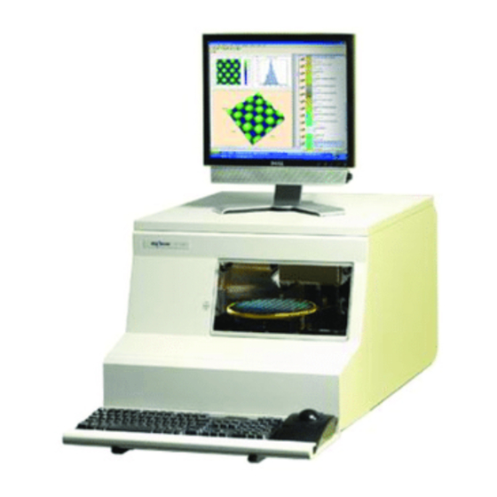
KLA-Tencor P-16+ / P-6 User’s Guide Introduction & Safety - Instrument Overview INTRODUCTION & SAFETY Chapter 1 NSTRUMENT VERVIEW The KLA-Tencor P-16+ / P-6 Profiler is a highly sensitive surface profiler that measures step height, roughness, and waviness on sample surfaces. The KLA-Tencor Profiler systems use stylus-based scanning to achieve high resolution. - Page 26 Introduction & Safety - Safety KLA-Tencor P-16+ / P-6 User’s Guide DANGER: Dangers indicate an imminently hazardous situation which, if not avoided, will result in death or serious injury. This signal word is limited to extreme situations. PINCH POINT: Pinch Point indicates a situation where the user, if not careful, could get a hand or finger pinched.
-
Page 27: Figure 1.1 Power Cord Plug Lockout/Tagout
KLA-Tencor P-16+ / P-6 User’s Guide Introduction & Safety - Safety Lockout/Tagout Procedure If the system is hardwired to facilities power, the lockout/tagout procedure is to be set by the system owner. Service personnel authorized to perform this type of lockout/tagout must be trained by the system owner in accordance with their set procedures. - Page 28 Introduction & Safety - Safety KLA-Tencor P-16+ / P-6 User’s Guide Place a padlock through one of the holes on the lockout hasp as shown in Figure 1.1, step 3. Make sure the device is secured in the closed position. Before locking the padlock, place the eyelet of an approved lockout tag over the hook of the padlock.
- Page 29 KLA-Tencor P-16+ / P-6 User’s Guide Introduction & Safety - Safety If none of the components are in motion when the door is opened, or when the interlock is tripped, the system can be activated again by closing the door or by returning the interlock to its normal operating position.
- Page 30 Introduction & Safety - Safety KLA-Tencor P-16+ / P-6 User’s Guide KLA-Tencor Confidential 0142530-000 AB 3/13/09...
-
Page 31: Chapter 2 Basic Skills
KLA-Tencor P-16+ / P-6 User’s Guide Basic Skills - Overview BASIC SKILLS Chapter 2 VERVIEW Before beginning the use of the P-16+ / P-6 Profiler system, become familiar with basic skills — such as starting and shutting down the system, and operating the system buttons, keyboard, trackball, Microsoft Windows, Profiler application, and other components RGONOMIC... -
Page 32: Powering U P The Profiler
Basic Skills - Powering Up the Profiler KLA-Tencor P-16+ / P-6 User’s Guide OWERING P THE ROFILER Introduction By powering up the computer, the system launches Windows. Power Up Procedure 1. Press the O button on the monitor to activate the monitor. 2. -
Page 33: Starting The Profiler Application
KLA-Tencor P-16+ / P-6 User’s Guide Basic Skills - Starting the Profiler Application 4. The E10 state is not being tracked by the software, so it can be left at the default value. 5. Click on Logon TARTING THE ROFILER PPLICATION Introduction The Profiler application is the interface with the P-16+/P-6 Profiler system from... -
Page 34: Figure 2.3 Profiler Catalog Screen
Basic Skills - Starting the Profiler Application KLA-Tencor P-16+ / P-6 User’s Guide 2. The system goes through its initiation at the end of which the Profiler Catalog screen appears. (See Figure 2.3.) Figure 2.3 Profiler Catalog Screen KLA-Tencor Confidential 0142530-000 AB Friday, March 13, 2009... -
Page 35: Avigating Etween Rogram Evel Creens
KLA-Tencor P-16+ / P-6 User’s Guide Basic Skills - Navigating Between Program Level Screens This is the starting point for operating the instrument. In this screen, scan and sequence recipes can be accessed for system operation. Each icon along the right side of the screen opens another application that contains the parameters or controls for a specific type of task. -
Page 36: Navigation Procedure
Basic Skills - Exiting the Profiler Application KLA-Tencor P-16+ / P-6 User’s Guide Navigation Procedure Use the following procedure to navigate between screens: Click the icon of the required program screen. (See Figure 2.4.) This closes the current program screen and accesses the chosen one. This could generate a message box that inquires if changes to settings, or data are to be saved or discarded. -
Page 37: Clearing A Status Bar Message
KLA-Tencor P-16+ / P-6 User’s Guide Basic Skills - Clearing a Status Bar Message 4. A Profiler Container (message box) appears asking, “Are you sure you want to exit the Profiler?” Click to exit. NOTE: The Profiler system will initialize upon shutdown.. 5. -
Page 38: Rotecting The Tylus Rm Ssembly
Basic Skills - Protecting the Stylus Arm Assembly KLA-Tencor P-16+ / P-6 User’s Guide ROTECTING THE TYLUS SSEMBLY System Provisions for Stylus Protection The P-16+ / P-6 Profiler incorporates several design features that protect the stylus from damage. (See Table 2.2) Table 2.2 Stylus Arm Assembly Protection Protection Name... -
Page 39: Figure 2.6 Contact Scan Stylus Tip
KLA-Tencor P-16+ / P-6 User’s Guide Basic Skills - Protecting the Stylus Arm Assembly The stylus can be damaged by a shorter object if it has sharp corners or burrs that bite into the stylus tip. Figure 2.6 Contact Scan Stylus Tip Scan Direction Damage can occur with steps... -
Page 40: Loading A Sample
Basic Skills - Loading a Sample KLA-Tencor P-16+ / P-6 User’s Guide When designing custom jigs or fixtures, consider the precautions noted in this section. For instance, when designing a custom hard disk locator, its center section must be flush with the top of the disk surface. Care must be exercised when nulling where there is a hole in a jig, a vacuum hole, or a groove in a surface. -
Page 41: Figure 2.8 Xy View Screen
KLA-Tencor P-16+ / P-6 User’s Guide Basic Skills - Loading a Sample Figure 2.8 XY View Screen Menu Bar Tool Bar Step 3 Click MAN LOAD to move the stage to the door. Video Display Window Sample Navigation Window 3. Click (see Figure 2.8) in the Tool Bar to move the stage to the door. -
Page 42: Adjusting The Video Image
Basic Skills - Adjusting the Video Image KLA-Tencor P-16+ / P-6 User’s Guide DJUSTING THE IDEO MAGE Introduction The Video Controls allow the view of a particular sample surface to be optimized. The brightness and contrast can be varied for the camera. NOTE: Changing the focus can invalidate sequences that use pattern recognition because the sample image is less likely to match the stored image in the pattern recognition files. -
Page 43: Sing Ile Ame Onventions
KLA-Tencor P-16+ / P-6 User’s Guide Basic Skills - Using File Name Conventions SING ONVENTIONS Introduction Scan and sequence recipes and data can be saved, as well as graphs and video images. In the Windows OS naming convention only the following special characters are allowed: Table 2.3 Special Characters Allowed for Naming Purposes... -
Page 44: Exporting Data Graphs
Basic Skills - Exporting Data Graphs KLA-Tencor P-16+ / P-6 User’s Guide XPORTING RAPHS Introduction Data graphs are contained in the Scan Data catalog, Sequence Data catalog and in the Analysis screen when the scan data is being analyzed. 2D and 3D graphs can be exported directly from the Analysis screen during scan data analysis. -
Page 45: Figure 2.12 Data Catalog Screen For Export Of Data Or Recipes
KLA-Tencor P-16+ / P-6 User’s Guide Basic Skills - Exporting Data Graphs 2. In the Database Catalog screen, choose either the button in the tool bar. Depending on the Catalog group chosen, this displays the 2D or 3D data or recipe sets. -
Page 46: Exporting Data From The Database File Manager
Basic Skills - Exporting Data from the Database File Manager KLA-Tencor P-16+ / P-6 User’s Guide 6. Set the required variables in the dialog box. See Table 2.4 for an Save As explanation of the variables to be set. Table 2.4 Graphics Export Dialog Features Variable Description... -
Page 47: Figure 2.14 Data Catalog Screen For Export Of Data Or Recipes
KLA-Tencor P-16+ / P-6 User’s Guide Basic Skills - Exporting Data from the Database File Manager 2. Choose either the Scan Data or Sequence Data catalog button. This displays the related 2D or 3D data files in the chosen catalog. Figure 2.14 Data Catalog Screen for Export of Data or Recipes Step 1 Click 2D or 3D to display related files. - Page 48 Basic Skills - Exporting Data from the Database File Manager KLA-Tencor P-16+ / P-6 User’s Guide 2-18 KLA-Tencor Confidential 0142530-000 AB Friday, March 13, 2009...
-
Page 49: Ntroduction
KLA-Tencor P-16+ / P-6 User’s Guide Scan Recipes - Introduction SCAN RECIPES Chapter 3 NTRODUCTION The P-16+ / P-6 Profiler system performs scans of sample surfaces using recipes that set the parameters of each scan. Each recipe can be used alone or, in conjunction with other recipes in a sequence to gather necessary data from a given sample. -
Page 50: Accessing The Scan Recipe Catalog Screen
Scan Recipes - Accessing the Scan Recipe Catalog Screen KLA-Tencor P-16+ / P-6 User’s Guide CCESSING THE ECIPE ATALOG CREEN The Catalog screen is the first screen to appear when the Profiler application is opened. The functional areas in the screen are described in Figure 3.1 and Figure 3.2. Figure 3.1 Catalog Sequence Recipe Screen The Control Button... -
Page 51: Recipe Catalog Screen
KLA-Tencor P-16+ / P-6 User’s Guide Scan Recipes - Scan Recipe Catalog Screen Components Figure 3.2 Catalog Sequence Recipe Screen When a recipe is chosen, its name appears in this box. The current path to the set of files displayed in the List window is shown here. -
Page 52: Figure 3.3 Title Bar For Catalog Screen
Scan Recipes - Scan Recipe Catalog Screen Components KLA-Tencor P-16+ / P-6 User’s Guide Title Bar The Title Bar contains the Control menu button, the Screen Title Bar, and the Close/Minimize icons (see Figure 3.3) or the GEM Status for systems equipped with the GEM/SECS option. -
Page 53: Figure 3.4 Menu Bar For Scan Recipe Screen
KLA-Tencor P-16+ / P-6 User’s Guide Scan Recipes - Scan Recipe Catalog Screen Components Menu Bar The following tables present the content of each drop-down menu in the Menu Bar for the screen. Scan Recipe Catalog NOTE: One or more of the menu options in a given drop-down menu might be grayed out. -
Page 54: Table 3.3 File Menu Options Description
Scan Recipes - Scan Recipe Catalog Screen Components KLA-Tencor P-16+ / P-6 User’s Guide Table 3.3 File Menu Options Description File Menu Description Starts the currently highlighted scan procedure. The screen changes to the scan START screen. In the screen depicted in Figure 3.2, it would start the recipe scan. -
Page 55: Table 3.6 Host Menu Options Description (Only Available With Gem/Secs Option)
KLA-Tencor P-16+ / P-6 User’s Guide Scan Recipes - Scan Recipe Catalog Screen Components Table 3.6 Host Menu Options Description (Only available with GEM/SECS Option) Host Menu Description This takes the P-16+ / P-6 Profiler system offline. This is used to prevent the Go Offline system from responding to a host during a user defined operation. -
Page 56: Figure 3.5 Toolbar Icons
Scan Recipes - Scan Recipe Catalog Screen Components KLA-Tencor P-16+ / P-6 User’s Guide ToolBar The ToolBar has eight icons that work as short cuts to functions. Figure 3.5 ToolBar Icons The function of each icon is described in Table 3.10. Table 3.10 ToolBar for the Scan Recipe Catalog Screen ToolBar Icon... -
Page 57: Catalog Screen Access Buttons
KLA-Tencor P-16+ / P-6 User’s Guide Scan Recipes - Scan Recipe Catalog Screen Components Catalog Screen Access Buttons The Catalog screen presents access to four sets of information. The Scan Recipe and the Sequence Recipe screen, provide access to the currently defined recipes available for execution in the P-16+ / P-6 Profiler system. -
Page 58: List Window
Scan Recipes - Scan Recipe Catalog Screen Components KLA-Tencor P-16+ / P-6 User’s Guide List Window List Window for Scan Recipe When the button is clicked, the List Window displays the Scan Recipe Scan Recipe information and associated function buttons. (See Figure 3.6.) Figure 3.6 Scan Recipe information in the List Window displays the currently... -
Page 59: Figure 3.7 Tool Bar Buttons
KLA-Tencor P-16+ / P-6 User’s Guide Scan Recipes - Scan Recipe Catalog Screen Components Recipe List Window This area contains the list of scan recipes that have been created for the various types of scans used by the system. Scan Recipes are categorized into 2D Scan recipes and 3D Scan recipes. -
Page 60: System Status Message
Scan Recipes - Creating and Editing a Scan Recipe KLA-Tencor P-16+ / P-6 User’s Guide Table 3.12 Scan Recipe List Window Function Access Buttons (Continued) Function Icon Description This opens the real-time display screen and begins the scan procedure associated with the currently highlighted scan recipe. -
Page 61: Accessing The Scan Recipe Editor
KLA-Tencor P-16+ / P-6 User’s Guide Scan Recipes - Creating and Editing a Scan Recipe Accessing the Scan Recipe Editor The actual creation of a scan recipe is performed in the Editor screen. This means that recipe creation and editing is restricted to those whose password permits access to the Recipe Editor. -
Page 62: Scan Parameter Definition Window
Scan Recipes - Creating and Editing a Scan Recipe KLA-Tencor P-16+ / P-6 User’s Guide Figure 3.9 Recipe Editor for a 2D UNTITLED Recipe The Title bar shows that the recipe name is currently and the screen UNTITLED Recipe Editor Each Parameter button displays its parameters in the Information Display... -
Page 63: Figure 3.11 2D Scan Category Parameters
KLA-Tencor P-16+ / P-6 User’s Guide Scan Recipes - Creating and Editing a Scan Recipe button displays four categories of 2D or 3D scan Scan Parameter Definition parameters: ; and 2D Scan 3D Scan Scan Time Stylus Vertical Ranging 2D Scan Category Parameters - Scan Parameters Definition The parameters defined in this category deal with the actual mechanics of the 2D scan. - Page 64 Scan Recipes - Creating and Editing a Scan Recipe KLA-Tencor P-16+ / P-6 User’s Guide μ - This parameter sets the speed at which the scan is Scan Speed ( μ μ performed. It has a range between , with numerous 25000 options within this range displayed in its drop-down menu and is not user-definable.
-
Page 65: Figure 3.13 Scan Trace Comparison - Large Vs. Small Stylus Radius
KLA-Tencor P-16+ / P-6 User’s Guide Scan Recipes - Creating and Editing a Scan Recipe Figure 3.13 illustrates the impact of stylus radius in generating a scan trace.. Figure 3.13 Scan Trace Comparison - Large vs. Small Stylus Radius Scan Direction Stylus A with large radius. -
Page 66: Figure 3.14 Data Collection When Using A Large Radius Stylus
Scan Recipes - Creating and Editing a Scan Recipe KLA-Tencor P-16+ / P-6 User’s Guide Figure 3.14 Data Collection When Using a Large Radius Stylus Stylus Path A (large radius stylus) - Stylus Path A (large radius stylus) - Low Frequency Data Collection High Frequency Data Collection Low and High Frequency Data Traces are nearly the same since a large radius... -
Page 67: Figure 3.15 Data Collection When Using A Small Radius Stylus
KLA-Tencor P-16+ / P-6 User’s Guide Scan Recipes - Creating and Editing a Scan Recipe Figure 3.15 Data Collection When Using a Small Radius Stylus Stylus Path B (small radius stylus) - Stylus Path B (small radius stylus) - Low Frequency Data Collection Medium Frequency Data Collection Stylus Path B (small radius stylus) - High Frequency Data Collection As the Data Points get closer (higher frequency), the Data Trace... - Page 68 Scan Recipes - Creating and Editing a Scan Recipe KLA-Tencor P-16+ / P-6 User’s Guide - This is a 2D option that allows the user to repeat a single Multi-Scan Average scan up to 10 times so that the scan data can be averaged by the number of scans performed.
-
Page 69: Table 3.13 Show Position Options
KLA-Tencor P-16+ / P-6 User’s Guide Scan Recipes - Creating and Editing a Scan Recipe Table 3.13 Show Position Options Option Description Graphic Representation Start setting is used in the Video portion of the XY Start Click here to position Start view screen to position the start of the scan at the intersection of the Video screen crosshairs. -
Page 70: Figure 3.17 Teach Scan Length, From The 2D Scan Teach Button
Scan Recipes - Creating and Editing a Scan Recipe KLA-Tencor P-16+ / P-6 User’s Guide Figure 3.17 Teach Scan Length, from the 2D Scan Teach Button With the feature in the field of view, click in the appropriate reference point (start, center, or end) for the scan. -
Page 71: Figure 3.18 3D Scan Parameters
KLA-Tencor P-16+ / P-6 User’s Guide Scan Recipes - Creating and Editing a Scan Recipe Table 3.14 3D Scan Parameters Summary (Continued) Parameter Setting 2D, 3D or Both Description and Location Multi-Scan Average The number of single identical scans which are performed and used to create a scan data set that represents the average of the scans. -
Page 72: Figure 3.19 Traces - Scan Perimeter With Traces
Scan Recipes - Creating and Editing a Scan Recipe KLA-Tencor P-16+ / P-6 User’s Guide Traces This assigns the number of scans that are made in the X-direction across the Y Scan direction. In Figure 3.19, the number in the variable box would be 8. -
Page 73: Table 3.15 Show Position Options
KLA-Tencor P-16+ / P-6 User’s Guide Scan Recipes - Creating and Editing a Scan Recipe Automatic Parameter Adjustment: - In general, a connection exists in the software such that, when certain parameters are changed, other parameters are readjusted to accommodate the changes. The adjustments occur between the Y Scan Size Traces parameters. -
Page 74: Figure 3.20 Scan Time - Scan Parameters Definition
Scan Recipes - Creating and Editing a Scan Recipe KLA-Tencor P-16+ / P-6 User’s Guide Scan Time Parameters (2D and 3D) - Scan Parameters Definition parameters box displays time and data point values, broken down into Scan Time general components. (See Figure 3.20.) No values can be set or defined in this portion of the screen. -
Page 75: Figure 3.21 Stylus Parameters (2D And 3D)
KLA-Tencor P-16+ / P-6 User’s Guide Scan Recipes - Creating and Editing a Scan Recipe ] + move time = For 2D and 3D X Scan Size Scan speed Individual Traces (s) - This is the total time that it takes to complete the set of scans Total (hr:min:s) defined in the scan recipe section, 3D Scan... -
Page 76: Table 3.16 Stylus Force Ranges For The Different Head Configurations
Scan Recipes - Creating and Editing a Scan Recipe KLA-Tencor P-16+ / P-6 User’s Guide Changing the setting: Applied Force Table 3.16 Stylus Force Ranges for the Different Head Configurations MicroHead V LF MicroHead V SR MicroHead V XR 0.05-50 mg 0.5-50 mg 0.5-50 mg 1. -
Page 77: Table 3.17 Range And Resolution Scan Parameters For The Microhead V Lf Head
KLA-Tencor P-16+ / P-6 User’s Guide Scan Recipes - Creating and Editing a Scan Recipe Range/Resolution This parameter sets the maximum size limit of the features that can be scanned in each given range, and the minimum feature size that can be resolved (positively detected). -
Page 78: Figure 3.22 Vertical Ranging - Profile Types
Scan Recipes - Creating and Editing a Scan Recipe KLA-Tencor P-16+ / P-6 User’s Guide If, in the course of a scan, the upper limit of any one of the ranges is reached, the Saturated Data Points system aborts the scan and a message is issued reporting that there are too many saturation data points. -
Page 79: Feature Detection (Only For 2D Scans)
KLA-Tencor P-16+ / P-6 User’s Guide Scan Recipes - Creating and Editing a Scan Recipe Table 3.20 Profile Types (Continued) Profile Type Range Description 131 μm 131 μm scans features ≈ 100 μm down from the scan’s starting point. 327 μm 1000 μm 327 μm scans features ≈... -
Page 80: Figure 3.23 Feature Detection - Recipe Editor
Scan Recipes - Creating and Editing a Scan Recipe KLA-Tencor P-16+ / P-6 User’s Guide Accessing the Feature Detection parameters: In the click the button. (See Figure 3.23.) For Recipe Editor, Feature Detection information on how to display the , see Accessing the Scan Recipe Recipe Editor Editor on page 13. -
Page 81: Figure 3.24 Feature Detection Point Locations On A Step
KLA-Tencor P-16+ / P-6 User’s Guide Scan Recipes - Creating and Editing a Scan Recipe Feature This parameter allows the user to choose between six different features that can be detected and identified during a scan. Figure 3.24 Feature Detection Point Locations on a Step Example of a Step feature UpEdge DownEdge... -
Page 82: Table 3.21 Feature Detection Descriptions (See Figure 3.24 And Figure 3.25.)
Scan Recipes - Creating and Editing a Scan Recipe KLA-Tencor P-16+ / P-6 User’s Guide Table 3.21 Feature Detection Descriptions (See Figure 3.24 and Figure 3.25.) Feature Description None No feature detection is being used. UpEdge At the trailing edge of a feature rise, it is the point at which the trace begins the plateau. -
Page 83: Detection Variables - Feature Detection - Recipe Editor
KLA-Tencor P-16+ / P-6 User’s Guide Scan Recipes - Creating and Editing a Scan Recipe For Up Edge, Up Base, Down edge, Down Base, Convex, and Concave: Feature Number If there are multiple edges detected in the scan, provides a way to Feature Number select a specific edge for detection. - Page 84 Scan Recipes - Creating and Editing a Scan Recipe KLA-Tencor P-16+ / P-6 User’s Guide Min. Plateau Width Minimum Plateau Width defines the minimum horizontal distance between rising and falling edges (or falling and rising edges). This parameter is useful to differentiate between features of similar shape, but different width.
-
Page 85: Scan Trace (Red) With First Derivative (Dark Blue) Overlaid On The Same Graph
KLA-Tencor P-16+ / P-6 User’s Guide Scan Recipes - Creating and Editing a Scan Recipe Figure 3.27 Scan Trace (Red) with First Derivative (Dark Blue) Overlaid on the Same Graph Deriviative without filtering does not produce clear inflection points at the rising and falling edges. -
Page 86: Filters And Cursors
Scan Recipes - Creating and Editing a Scan Recipe KLA-Tencor P-16+ / P-6 User’s Guide Filters and Cursors Filters Two filters are available for removing noise from scan data, either as the scan is taking place, or after the scan occurs but before the data is saved. The oldest filter is the RC Filter. -
Page 87: Figure 3.29 Cursor Parameters - Recipe Editor
KLA-Tencor P-16+ / P-6 User’s Guide Scan Recipes - Creating and Editing a Scan Recipe 2. Click the desired value or type in the desired value. Long Wavelength Cutoff NOTE: The availability of cutoffs is dependent on the scan speed. The systems prevents the accidental entry of a long wavelength cutoff that is shorter than the currently selected short wavelength cutoff or the value of the analog cutoff. -
Page 88: Analysis Screen With Trace In Need Of Leveling
Scan Recipes - Creating and Editing a Scan Recipe KLA-Tencor P-16+ / P-6 User’s Guide Figure 3.30 Analysis Screen with Trace in Need of Leveling The Leveling Cursors are the top set The Measurement Cursors are the bottom set. The trace is shown running from the top left to the bottom right of the screen. -
Page 89: Figure 3.31 Cursor Boundary Setting On Unleveled Trace
KLA-Tencor P-16+ / P-6 User’s Guide Scan Recipes - Creating and Editing a Scan Recipe b. Click and hold the mouse button while using the track ball to drag the boundary into position for leveling the scan. Release the mouse button when the boundary is correctly positioned. -
Page 90: Setting Measurement Cursors
Scan Recipes - Creating and Editing a Scan Recipe KLA-Tencor P-16+ / P-6 User’s Guide 1. It is important to set the measurement cursors to accurately measure the desired feature. In Figure 3.32 the left cursor is set on the sample surface with the cursor borders positioned to measure a relatively flat trace segment. -
Page 91: Cursor Parameters - Recipe Editor
KLA-Tencor P-16+ / P-6 User’s Guide Scan Recipes - Creating and Editing a Scan Recipe b. As the track ball cursor approaches one of the active cursors, the cursor header changes to appear indented and the track ball cursor appears as a double arrow as shown in Figure 3.6. -
Page 92: Measurement Cursors - Relative To Feature Detection
Scan Recipes - Creating and Editing a Scan Recipe KLA-Tencor P-16+ / P-6 User’s Guide Relative to Feature Detected When there is a check ( ) in its checkbox, the cursor limits are set relative to the feature that is defined in the parameters window in the Feature Detection Recipe... - Page 93 KLA-Tencor P-16+ / P-6 User’s Guide Scan Recipes - Creating and Editing a Scan Recipe Median Filter for 2D and 3D Data This filter can be chosen as part of the recipe to help filter out spikes from environmental noise and particulate contamination. A median filter can be turned on before the scan, allowing the system to filter the data before the first viewing.
-
Page 94: Figure 3.36 Median Filter Application In Glitch Removal
Scan Recipes - Creating and Editing a Scan Recipe KLA-Tencor P-16+ / P-6 User’s Guide Figure 3.36 Median Filter Application in Glitch Removal BEFORE APPLICATION 1 x 3 point median filter AFTER APPLICATION before and after application Notice how much smoother the 1 x 7 filter (below) made the scan than that of the 1 x 3 filter (above). -
Page 95: Figure 3.37 2D And 3D Median Filter Options
KLA-Tencor P-16+ / P-6 User’s Guide Scan Recipes - Creating and Editing a Scan Recipe 3. Click to display the Filters and Cursors parameters. Filters/Cursors 4. Click the menu-arrow for either the 2D or 3D Median Filter to display the options. -
Page 96: Filters Cursors Menu For A 3D Recipe
Scan Recipes - Creating and Editing a Scan Recipe KLA-Tencor P-16+ / P-6 User’s Guide Apply Filter The Apply Filter option is enabled by default. This means that the filter is applied to every 3D scan that meets the parameters described in the Y Lead Screw Filter Constraints. -
Page 97: Figure 3.39 3D Measurement Cursor Box
KLA-Tencor P-16+ / P-6 User’s Guide Scan Recipes - Creating and Editing a Scan Recipe 3D Measurement Cursor The 3D measurement cursor is used to isolate an area of the scan, from which the measurements designated in the recipe for inclusion in the Analysis data (such as some of the parameters in General Parameters on page 51 and Roughness and Waviness Parameters on page 55), can be reported. -
Page 98: Figure 3.40 Recipe Editor - Choosing 3D Cursors
Scan Recipes - Creating and Editing a Scan Recipe KLA-Tencor P-16+ / P-6 User’s Guide Figure 3.40 Recipe Editor - Choosing 3D Cursors To open the 3D Cursors window, click Filters Cursors. Click to put a check in the check box to activate the X Start Level. -
Page 99: Unit Output
KLA-Tencor P-16+ / P-6 User’s Guide Scan Recipes - Creating and Editing a Scan Recipe Unit Output Unit Output is designed to give the user an opportunity to determine units of output for the parameters calculated and to set automatic crossover values for unit changes. The options here let the user choose the units for the 2D graphical display through the recipe that is used to generate the scan. -
Page 100: Figure 3.42 General Parameters - Recipe Editor
Scan Recipes - Creating and Editing a Scan Recipe KLA-Tencor P-16+ / P-6 User’s Guide Figure 3.42 General Parameters - Recipe Editor To display the General Parameters options in the Information Display window of the Recipe Editor, click the General Parameters The 3D options are button. -
Page 101: Table 3.22 2D General Parameters
KLA-Tencor P-16+ / P-6 User’s Guide Scan Recipes - Creating and Editing a Scan Recipe Each parameter is discussed below. (See Figure 3.42.) Table 3.22 2D General Parameters Parameter Description Step Height (StpHt) The difference in height between the left and right measurement cursors positions. - Page 102 Scan Recipes - Creating and Editing a Scan Recipe KLA-Tencor P-16+ / P-6 User’s Guide Table 3.22 2D General Parameters (Continued) Parameter Description Peak (Pp) Maximum Z value, measured relative to the leveled reference line, between the left and right measurement cursors. Valley (Pv) Minimum Z value, measured relative to the leveled reference line, between the left and right measurement cursors.
-
Page 103: Roughness And Waviness Parameters
KLA-Tencor P-16+ / P-6 User’s Guide Scan Recipes - Creating and Editing a Scan Recipe Either one or both calculation options can be used. If both are used, two sets of calculations are performed and presented in the Analysis screen. Table 3.23 3D General Parameters Parameter... -
Page 104: Figure 3.43 Waviness Vs. Roughness
Scan Recipes - Creating and Editing a Scan Recipe KLA-Tencor P-16+ / P-6 User’s Guide For applications where the user is unsure of a specific long wavelength cutoff, use the μ general rule of 1/5 the scan length. This means that for a scan of 50 m, the cutoff μ... -
Page 105: Figure 3.45 Recipe Editor Showing 2D And 3D Roughness/Waviness Parameters
KLA-Tencor P-16+ / P-6 User’s Guide Scan Recipes - Creating and Editing a Scan Recipe Figure 3.45 shows the Recipe Editor with the Roughness and Waviness parameters in the Information Display window. Figure 3.45 Recipe Editor Showing 2D and 3D Roughness/Waviness Parameters 0142530-000 AB KLA-Tencor Confidential 3-57... -
Page 106: Table 3.24 2D Roughness Parameters
Scan Recipes - Creating and Editing a Scan Recipe KLA-Tencor P-16+ / P-6 User’s Guide 2D Roughness Parameters Each of the roughness parameters available in the option 2D Roughness Parameters box are described in Table 3.24 on page 3-58. (For more information Roughness, see the Introduction to Roughness and Waviness Parameters on page 3-55.) Table 3.24 2D Roughness Parameters... - Page 107 KLA-Tencor P-16+ / P-6 User’s Guide Scan Recipes - Creating and Editing a Scan Recipe Table 3.24 2D Roughness Parameters (Continued) Parameter Description Roughness Height (R The difference in height in the roughness profile between the left and right cursor positions. Analogous to the Height data that always appears in the Summary box of the Analysis window.
-
Page 108: Table 3.25 2D Waviness Parameters
Scan Recipes - Creating and Editing a Scan Recipe KLA-Tencor P-16+ / P-6 User’s Guide 2D Waviness Parameters Table 3.25 2D Waviness Parameters Parameter Description Average (W This is the arithmetic average deviation of the absolute values of the waviness profile from the mean line or centerline also known as centerline average waviness). -
Page 109: Figure 3.46 3D Roughness Parameters
KLA-Tencor P-16+ / P-6 User’s Guide Scan Recipes - Creating and Editing a Scan Recipe Figure 3.46 3D Roughness Parameters Either or both of the options for each parameter can be chosen. Each parameter option can be calculated in two different ways: With this checkbox selected, the parameter are calculated using data Full Scale: from the entire scan. - Page 110 Scan Recipes - Creating and Editing a Scan Recipe KLA-Tencor P-16+ / P-6 User’s Guide Table 3.26 3D Roughness Parameters (Continued) Parameter Description Kurtosis (S A measure of the peakedness or sharpness of the surface height distribution. It characterizes the spread of the height distribution.
-
Page 111: Bearing Ratio And Cutting Depth
KLA-Tencor P-16+ / P-6 User’s Guide Scan Recipes - Creating and Editing a Scan Recipe Bearing Ratio and Cutting Depth Access the Bearing Ratio and Cutting Depth Information Display window by clicking the Bearing Ration/Cutting Depth button in the Recipe Editor. (See Figure 3.47.) Figure 3.47 Bearing Ration and Cutting Depth Parameters Bearing Ratio (t... -
Page 112: Figure 3.48 2D Bearing Ratio
Scan Recipes - Creating and Editing a Scan Recipe KLA-Tencor P-16+ / P-6 User’s Guide 1. The option exists to create three 2D bearing ratio parameters. Click in up to three empty checkboxes to put a check ( ) in them and activate their variable boxes. -
Page 113: Figure 3.50 Cutting Depth
KLA-Tencor P-16+ / P-6 User’s Guide Scan Recipes - Creating and Editing a Scan Recipe 1. The option exists to create three 2D cutting depth parameters. Click in up to three empty checkboxes to put a check ( ) in them and activate their variable boxes. - Page 114 Scan Recipes - Creating and Editing a Scan Recipe KLA-Tencor P-16+ / P-6 User’s Guide 4. The is the distance down from the top of the highest point in the scan. To Depth set or change the , double-click the current variable and type in the Depth Depth...
-
Page 115: High Spot Count And Peak Count
KLA-Tencor P-16+ / P-6 User’s Guide Scan Recipes - Creating and Editing a Scan Recipe High Spot Count and Peak Count Access the High Spot Count and Peak Count Display Window by clicking the High button in the Recipe Editor. (See Figure 3.51.) Spot Count/Peak Count Figure 3.51 Bearing Ratio and Cutting Depth Parameters... -
Page 116: Figure 3.52 High Spot Count
Scan Recipes - Creating and Editing a Scan Recipe KLA-Tencor P-16+ / P-6 User’s Guide Projecting through means that the profile curve first climbs above the reference line and then falls below it. Thus, if the profile rises above the reference line, descends without falling below it, then rises again, multiple peaks are not identified. -
Page 117: Figure 3.53 Peak Count
KLA-Tencor P-16+ / P-6 User’s Guide Scan Recipes - Creating and Editing a Scan Recipe 4. The is the distance up from the lowest point of the roughness trace. In Height most scans, this value is compared to High Spot Count (HSC) so this height must be identical to the Height High Spot Count (HSC) -
Page 118: Histogram Leveling And Depth Analysis
Scan Recipes - Creating and Editing a Scan Recipe KLA-Tencor P-16+ / P-6 User’s Guide 2D Mean Spacing Sm (1/PC) Mean Peak spacing is the mean value of the local peak spacing of the profile within the sampling length. The peaks for Peak Count are defined by the (bandwidth) Band parameter from the Peak Count (PC) window. - Page 119 KLA-Tencor P-16+ / P-6 User’s Guide Scan Recipes - Creating and Editing a Scan Recipe Leveling Reference The system offers the following data planes to choose from for leveling the scan data: Most Populous Plane Highest Plane Lowest Plane All Data Planes The leveling takes place based upon the data points identified in one of the three data distribution planes identified above.
-
Page 120: Figure 3.55 Histogram Leveling Parameters
Scan Recipes - Creating and Editing a Scan Recipe KLA-Tencor P-16+ / P-6 User’s Guide Figure 3.55 Histogram Leveling Parameters In Figure 3.60, Scan A shows that the major distribution of points lie clearly in Z Min, Z Mid, and Z Max. The histogram of this distribution would be clearly presented in three ranges. -
Page 121: Histograms Of Scans A And B
KLA-Tencor P-16+ / P-6 User’s Guide Scan Recipes - Creating and Editing a Scan Recipe Figure 3.56 Histograms of Scans A and B Scan A Bin Number Z Min Z Mid Z Max Lowest Plane Most Populous Plane Highest Plane Scan B Bin Number Z Min... -
Page 122: Figure 3.58 Flat Surface Scan Of A Single Object
Scan Recipes - Creating and Editing a Scan Recipe KLA-Tencor P-16+ / P-6 User’s Guide Leveling Reference Three reference planes exist, from which one must be chosen to level the scan. Two of the planes are easy to understand and use; the Highest Plane and Lowest Plane. Highest Plane –... -
Page 123: Figure 3.59 Most Populous Plane Trace Variation
KLA-Tencor P-16+ / P-6 User’s Guide Scan Recipes - Creating and Editing a Scan Recipe The scan illustrated in Figure 3.59 would not be an acceptable candidate for Most Populous Plane. This scan has four traces that would give different data sets depending on which trace was used to level the scan. -
Page 124: Histogram Depth
Scan Recipes - Histogram Depth KLA-Tencor P-16+ / P-6 User’s Guide Figure 3.60 Histogram of a Scan Z Max Z Mid Z Min Bin Number Z Min Z Mid Z Max Lowest Plane (Mode) Most Populous Plane (Mode) Highest Plane (Mode) In the Histograms, the different planes (modes) are color coded for easy reference and identification. -
Page 125: Cmp Analysis
KLA-Tencor P-16+ / P-6 User’s Guide Scan Recipes - CMP Analysis Figure 3.61 Histogram Depth CMP A NALYSIS Introduction CMP (Chemical Mechanical Polishing) processes are used on a variety of different surface compositions. In general, the analysis of CMP surface scans centers around three structures: arrays, lines, and pads. -
Page 126: Figure 3.62 Cmp Analysis - Lines Or Array
Scan Recipes - CMP Analysis KLA-Tencor P-16+ / P-6 User’s Guide Figure 3.62 CMP Analysis - Lines or Array 3-78 KLA-Tencor Confidential 0142530-000 AB 3/13/09... -
Page 127: Figure 3.63 Cmp Analysis - Pads
KLA-Tencor P-16+ / P-6 User’s Guide Scan Recipes - CMP Analysis Figure 3.63 CMP Analysis - PADS 0142530-000 AB KLA-Tencor Confidential 3-79 3/13/09... -
Page 128: Arrays
Scan Recipes - CMP Analysis KLA-Tencor P-16+ / P-6 User’s Guide Arrays For the purposes of this analysis, “array” is defined as an array of contacts or vias (plugs). The contacts or vias are usually a metal like tungsten or copper which typically have polish rates higher than that of the surrounding array oxide. -
Page 129: Figure 3.65 Er And Cr
KLA-Tencor P-16+ / P-6 User’s Guide Scan Recipes - CMP Analysis The “erosion region” (ER) is found by determining the minimum and maximum slopes in the profile. The “calculations region” (CR) is defined as some fraction of the ER. Figure 3.65 ER and CR Curve A Curve B Determine the local maxima within the CR. -
Page 130: Lines
Scan Recipes - CMP Analysis KLA-Tencor P-16+ / P-6 User’s Guide Lines For the purposes of this analysis, “lines” is defined as an intermittent distribution of metal and oxide lines. The metal line are usually a soft metal like aluminum or copper which typically have polish rates higher than that of the surrounding array oxide. -
Page 131: Pads
KLA-Tencor P-16+ / P-6 User’s Guide Scan Recipes - CMP Analysis Determine the vertical range of data within the CR. Determine the local maxima within the CR using a window of variable size. The size of the window is roughly equivalent to the pitch of the lines. -
Page 132: Feature Find
Scan Recipes - Feature Find KLA-Tencor P-16+ / P-6 User’s Guide Using the PADS Analysis Routine This routine is designed to perform analysis on both 2D and 3D Profiler data. The same set of input parameters are used for 2D and 3D data belonging to a single recipe, e.g., 2D slices from a 3D data set. -
Page 133: Figure 3.68 Feature Find Parameter Definition
KLA-Tencor P-16+ / P-6 User’s Guide Scan Recipes - Feature Find recipe and then clicking the Define button. If the option Model Feature is selected the recipe editor selections will change slightly to display different options. Table 3.27 contains a short description of the recipe parameters. Each parameter is discussed in detail as well. -
Page 134: Search For: Trench / Line
Scan Recipes - Feature Find KLA-Tencor P-16+ / P-6 User’s Guide Table 3.27 Feature Find Recipe Parameters (Continued) Parameter Setting Sensor or Oval, Description Sample Trench or Model X Scan Size (μm) Both X direction scan size of the feature find scan Traces Both This is the maximum number of x direction scans... -
Page 135: Figure 3.69 Trench / Line Features
KLA-Tencor P-16+ / P-6 User’s Guide Scan Recipes - Feature Find process continues until a feature is found or until all x scan lines have been attempted. If no x scan lines find a feature, then the Feature Find scan failed. If during any of the x scan lines a feature is found that meets the requirements, the remaining x scans are canceled and the found coordinate becomes the Feature Find offset, which is the center point of the measurement scan. -
Page 136: Search For Model Feature
Scan Recipes - Feature Find KLA-Tencor P-16+ / P-6 User’s Guide Figure 3.70 Trench / Line Scan Search For Model Feature Model Feature definition is for features that are not easily defined as a rectangle or line. These features can be of irregular shape, an edge, or attempting to find a feature at the edge of an array for repeatability testing, as shown in Figure 3.71. -
Page 137: Figure 3.71 Edge Of An Array Of 5 Μm Lines
KLA-Tencor P-16+ / P-6 User’s Guide Scan Recipes - Feature Find Figure 3.71 Edge of an Array of 5 µm Lines Scan data is saved as model, such as the model shown below. This model is for the edge of the array, with the top two lines including the 5 m lines and μ... -
Page 138: Figure 3.73 Model Feature Scan
Scan Recipes - Feature Find KLA-Tencor P-16+ / P-6 User’s Guide Example: Model Feature Search for the Edge of an Array of 5µm Lines ♦ Four x scans are performed, lines one through four, from Bottom to Top, to build a scan size equal to the number of lines as the model size. ♦... -
Page 139: Search Patterns: Center Outward, Top To Bottom
KLA-Tencor P-16+ / P-6 User’s Guide Scan Recipes - Feature Find Search Patterns: Center Outward, Top to Bottom, or Bottom to Top There are three different search patterns that can be used in combination with any of the search types. All of the search patterns can be used with sensor or sample stage measurements. -
Page 140: Y Spacing (Μm)
Scan Recipes - Feature Find KLA-Tencor P-16+ / P-6 User’s Guide recipe, the number of Traces is limited to 2000. When setting up a sensor stage recipe, the allowable number of Traces is limited to 200 and is also limited by the recipe y size, and Feature Find Y Spacing and any offsets, with the total summing to less than the 90 µm scan size limitation for the sensor stage. -
Page 141: Failure Option: Save Search Data, Skip Current Scan, Or Scan At Center
KLA-Tencor P-16+ / P-6 User’s Guide Scan Recipes - Feature Find Failure Option: Save Search Data, Skip Current Scan, or Scan at Center The choice of Failure Option depends on the preference of the user and the purpose of the Feature Find scan. When running a recipe with a Feature Find scan in a sequence recipe, if the option to Save Search Data is selected, after the Feature Find fails, it will save the x scan search data in the sequence data set and proceed to the next measurement site. -
Page 142: Feature Characteristics: Feature Down Or Feature Up
Scan Recipes - Feature Find KLA-Tencor P-16+ / P-6 User’s Guide Figure 3.74 5µm Lines Measurement Pattern Feature Characteristics: Feature Down or Feature Up When using the Oval / Rectangle and Trench / Line search types the user must define the physical characteristics of the feature. Feature Down or Feature Up defines if the feature is below or above the sample surface. -
Page 143: Model
KLA-Tencor P-16+ / P-6 User’s Guide Scan Recipes - Feature Find filter size for the Feature Find scan. So if the tolerance is set too large, then a large filter can be applied which will affect the scan and Feature Find search performance. -
Page 144: Matching Methods: Edge Base Or Depth Base
Scan Recipes - Feature Find KLA-Tencor P-16+ / P-6 User’s Guide Figure 3.75 Feature Find Definition for Model Feature Matching Methods: Edge Base or Depth Base Edge Based matching method is the setting for most applications. It used the x and y edges of features in the model and compares it to the Feature Find scan data. -
Page 145: Matching Scores
KLA-Tencor P-16+ / P-6 User’s Guide Scan Recipes - Feature Find Figure 3.76 Dual Damascene Example for Model Feature using Depth Based Matching Matching Scores The Matching Scores function in the way as the scores for sequence recipe pattern recognition. As each Feature Find scan line completes, a pattern recognition score is given that shows how well the model matches the scan data. -
Page 146: Reference Point (Μm)
Scan Recipes - Feature Find KLA-Tencor P-16+ / P-6 User’s Guide NOTE: The Model Feature pattern recognition scores will be shown on the status bar during the Feature Find scan. When optimizing the recipe, these scores should be noted to ensure that the High and Low matching scores are set properly. -
Page 147: Table 3.28 Diagnostic Options
KLA-Tencor P-16+ / P-6 User’s Guide Scan Recipes - Feature Find Diagnostic Options Listed below are options located in the Diagnostic options window. Table 3.28 Diagnostic Options Option Description No Motion Scan During the scan, data is collected but the stage does not move. -
Page 148: Entering Comments
Scan Recipes - Feature Find KLA-Tencor P-16+ / P-6 User’s Guide Entering Comments Introduction This feature is designed for recording important comments about the recipe. The only field that is active for user input is the Comments: field. The other fields are automatically set by the system to reflect the specific recipe. -
Page 149: Chapter 4 Xy View Screen
KLA-Tencor P-16+ / P-6 User’s Guide XY View Screen - Introduction XY VIEW SCREEN Chapter 4 NTRODUCTION The name XY View comes from the function of the screen itself, which is for viewing the sample surface, and positioning a scan. The XY View screen also provides other tools required to set up and perform a scan. - Page 150 XY View Screen - Starting the XY View Application KLA-Tencor P-16+ / P-6 User’s Guide XY View Menu Bar The Menu Bar contains the majority of the available screen function commands. Each function is explained in detail in this section. KLA-Tencor Confidential 0142530-000 AB 3/13/09...
-
Page 151: Table 4.1 View Menu Description
KLA-Tencor P-16+ / P-6 User’s Guide XY View Screen - Starting the XY View Application View Menu Table 4.1 View Menu Description View Menu Description Focus Using the current magnification setting, this button causes the system to focus on the sample that is on the stage at the same time that the stylus is nulled on the sample surface. -
Page 152: Table 4.2 Die Grid Menu
XY View Screen - Starting the XY View Application KLA-Tencor P-16+ / P-6 User’s Guide Die Grid Menu (Optional Feature with Pattern Recognition Option, P-16+ Only) Table 4.2 Die Grid Menu Die Grid Menu Description Load… Displays the dialog box used to load a die grid pattern. -
Page 153: Figure 4.2 Move Extents Dialog Box
KLA-Tencor P-16+ / P-6 User’s Guide XY View Screen - Starting the XY View Application Move Menu Table 4.3 Move Menu Move Menu Description Slow – Sets the XY stage to move in the slowest, or smallest increment, speed as defined in the Move Extents Medium –... -
Page 154: Table 4.4 Direction Menu
XY View Screen - Starting the XY View Application KLA-Tencor P-16+ / P-6 User’s Guide Direction Menu Table 4.4 Direction Menu Direction Menu Description Up – Moves the stage in the +Y direction away from the front door by one increment (as defined in for the set speed) per Move Speeds... -
Page 155: Table 4.5 Actions Menu
KLA-Tencor P-16+ / P-6 User’s Guide XY View Screen - Starting the XY View Application Actions Menu Table 4.5 Actions Menu Actions Menu Description Start Scan Starts the scan process. View Scan Changes to the View Scan window. Sample Menu Table 4.6 Sample Menu Sample Menu... -
Page 156: Figure 4.4 Distance Dialog Box
XY View Screen - Starting the XY View Application KLA-Tencor P-16+ / P-6 User’s Guide Stylus Menu Table 4.8 Stylus Menu Stylus Menu Description Drop/Lift (Applicable to P/16+ only) Causes the stylus to pivot up. A check mark is visible while it is in the UP position. Click it to release it back to its normal scanning position Distance…... -
Page 157: Setting The Magnification
The system has an optical zoom function that allows the operator to view the sample surface at different magnifications for feature identification and scan placement. If the system has Pattern Recognition operating (P-16+only), zooming in and out could prevent the system from performing accurately because the recognition function also takes into consideration the size of the image as well as its shape. -
Page 158: Changing The Magnification
XY View Screen - Setting the Magnification KLA-Tencor P-16+ / P-6 User’s Guide Changing the Magnification Click the to change the magnification. Each click changes the ZOOM IN ZOOM OUT magnification level in or out by a small amount. (Alternative: In the Menu bar click to display its menu. -
Page 159: Focusing The View
KLA-Tencor P-16+ / P-6 User’s Guide XY View Screen - Focusing the View 3. Ensure that the zoom position in the dialog box field agrees with the Zoom Zoom in the screen display. (See Figure 4.6.) Position 4. Click the check box. -
Page 160: P-16+ Microhead Measurement Head
XY View Screen - Focusing the View KLA-Tencor P-16+ / P-6 User’s Guide 3. Open the measurement chamber door and then the head door. (See Figure 4.7.) Figure 4.7 P-16+ MicroHead Measurement Head. Top Panel Stylus Protection Plate Camera Status Indicators Stylus Wrench Optics... -
Page 161: Positioning The Scan Site
KLA-Tencor P-16+ / P-6 User’s Guide XY View Screen - Positioning the Scan Site 6. If the side view requires focusing, use the Side-View Focus knob to focus the side view. (See Figure 4.8) Figure 4.8 P-16+ Focusing the Optics (Dual-View Optics). Side-View Focus Knob (P-16+ Only) -
Page 162: Figure 4.9 Coordinate System Of The Kla-Tencor Profiler Stage
XY View Screen - Positioning the Scan Site KLA-Tencor P-16+ / P-6 User’s Guide Figure 4.9 shows the stage coordinate system (SEMI Standard M20-92) used by the Profiler. The X and Y coordinates relative to the center of the measurement area are displayed in the current stage coordinate area of the XY View window. -
Page 163: Figure 4.10 Xy View Screen Tool Bar
KLA-Tencor P-16+ / P-6 User’s Guide XY View Screen - Positioning the Scan Site Table 4.10 Locating a Scan Site Movement Required Movement Method Move in increments Arrow Buttons Positioning – Click the Fast , or buttons (move extents) to change Medium Slow across the sample using... -
Page 164: Using Die Grid Navigation (Optional Feature , P-16+ Only )
XY View Screen - Using Die Grid Navigation (Optional Feature, P-16+ only) KLA-Tencor P-16+ / P-6 User’s Guide 3. Click the button to null the stylus on the sample and confirm the Stylus Drop-Lift scan position. Figure 4.11 XY View Screen Video Display Window Sample Navigation Window... -
Page 165: Figure 4.12 Teach Die Grid Screen With Loaded Die Grid
KLA-Tencor P-16+ / P-6 User’s Guide XY View Screen - Using Die Grid Navigation (Optional Feature, P-16+ only) Figure 4.12 Teach Die Grid Screen with Loaded Die Grid Current : The die Die Scan Position currently being scanned is highlighted. Die Grid Navigation Window: This is a representation of the current die grid loaded in the... -
Page 166: Creating A Die Grid
XY View Screen - Using Die Grid Navigation (Optional Feature, P-16+ only) KLA-Tencor P-16+ / P-6 User’s Guide In making it more convenient to position scans on a wafer, Die Grid Navigation provides the following options: Mask out the dies that are not to be measured. Masked dies appear blacked out on the Die Grid Navigation Window, providing visual reference points. -
Page 167: Figure 4.13 Scan Catalog Screen
KLA-Tencor P-16+ / P-6 User’s Guide XY View Screen - Using Die Grid Navigation (Optional Feature, P-16+ only) Figure 4.13 Scan Catalog Screen Step 1 Click the Scan Recipe button to open the list of available Step 2 Click the Die Grid icon to initiate the Teach... -
Page 168: Figure 4.15 Teach Die Grid Screen
XY View Screen - Using Die Grid Navigation (Optional Feature, P-16+ only) KLA-Tencor P-16+ / P-6 User’s Guide 3. Click to continue with the procedure. (See Figure 4.14.) 4. In the screen, the procedure is prompted from the message Teach Die Grid display area at the bottom left of the screen. -
Page 169: Figure 4.16 Teach Die Grid - Teach First Position
KLA-Tencor P-16+ / P-6 User’s Guide XY View Screen - Using Die Grid Navigation (Optional Feature, P-16+ only) 10. Click when all variables are correct. Figure 4.16 Teach Die Grid - Teach First Position Step 11 The graphic represents a single die. The thick gray border is the area between the various dies on the wafer. -
Page 170: Figure 4.17 Teach Die Grid - Teach Feature
XY View Screen - Using Die Grid Navigation (Optional Feature, P-16+ only) KLA-Tencor P-16+ / P-6 User’s Guide Figure 4.17 Teach Die Grid - Teach Feature Step 12 Use the arrow buttons to locate a distinct feature. Use the click and drag procedure to draw a box around the feature. -
Page 171: Figure 4.18 Teach Die Grid - Lower Right Corner
KLA-Tencor P-16+ / P-6 User’s Guide XY View Screen - Using Die Grid Navigation (Optional Feature, P-16+ only) 14. After making any required adjustments, click If the die width and height were not entered, the instrument continues to the third position in the Teach Die Grid sequence: Figure 4.18 Teach Die Grid - Lower Right Corner Step 15 Use the arrow buttons... -
Page 172: Figure 4.19 Teach Die Grid - With Feature In Navigation Window
XY View Screen - Using Die Grid Navigation (Optional Feature, P-16+ only) KLA-Tencor P-16+ / P-6 User’s Guide Figure 4.19 Teach Die Grid - With Feature in Navigation Window The feature appears in the navigation window, above the text explaining the current system activity. -
Page 173: Loading A Die Grid (Turning On Die Grid Navigation) For A Single Scan
KLA-Tencor P-16+ / P-6 User’s Guide XY View Screen - Using Die Grid Navigation (Optional Feature, P-16+ only) At the bottom of the die grid navigation window is a representation of the die grid, which appears as a bounded white rectangle. The taught feature is pictured a small bounded box appearing in its relative position in the die. -
Page 174: Figure 4.21 Sequence Editor With Die Grid Menu
XY View Screen - Using Die Grid Navigation (Optional Feature, P-16+ only) KLA-Tencor P-16+ / P-6 User’s Guide Figure 4.21 Sequence Editor with Die Grid Menu Step 2 Click to display its Grid menu. Step 3 Click to display Load... the Load Die Grid dialog box. -
Page 175: Figure 4.22 Load Sequence Die Grid
KLA-Tencor P-16+ / P-6 User’s Guide XY View Screen - Using Die Grid Navigation (Optional Feature, P-16+ only) 4. In the dialog box, double-click the name of the die grid to be used. Load Die Grid This displays die grid name in the File Name display box. Figure 4.22 Load Sequence Die Grid Step 4 To choose a die grid to... -
Page 176: Clearing A Die Grid (Turn Off Die Grid Navigation)
XY View Screen - Using Die Grid Navigation (Optional Feature, P-16+ only) KLA-Tencor P-16+ / P-6 User’s Guide Clearing a Die Grid (Turn OFF Die Grid Navigation) 1. Go to the window. Teach Scan 2. Click the menu, and select . -
Page 177: Displaying Grid Numbers In The Die Grid Navigation Window
KLA-Tencor P-16+ / P-6 User’s Guide XY View Screen - Aligning the Sample Displaying Grid Numbers in the Die Grid Navigation Window From a window, click , then click (See Teach Scan Site Die Grid Display Numbers Figure 4.23.)click If the numbers are too small to see, increase the size of the Die Grid Navigation Window by clicking and dragging the window’s vertical separator bar to the left. -
Page 178: Figure 4.24 Setting Alignment Angle
XY View Screen - Aligning the Sample KLA-Tencor P-16+ / P-6 User’s Guide 4. Click in the tool bar to display its menu. In the menu, click View Align Sample This sets up the procedure which aligns the XY axis of the Alignment Sample screen with the chosen feature. -
Page 179: Figure 4.25 Move Menu
KLA-Tencor P-16+ / P-6 User’s Guide XY View Screen - Aligning the Sample 2. Use the theta movement arrows in the tool bar (in conjunction with the other arrow buttons as necessary) to rotate the chosen feature until it aligns with the X-axis on the XY view screen. - Page 180 XY View Screen - Aligning the Sample KLA-Tencor P-16+ / P-6 User’s Guide 4-32 KLA-Tencor Confidential 0142530-000 AB 3/13/09...
-
Page 181: Chapter 5 View Scan Window
KLA-Tencor P-16+ / P-6 User’s Guide View Scan Window - 2D Screen Function VIEW SCAN WINDOW Chapter 5 2D S CREEN UNCTION appears while a scan is being run. It allows the user to observe View Scan Window the progress of the scan and to adjust scan parameters in the various screens for optimum scan results. -
Page 182: 2D Scan Information Field
View Scan Window - 2D Screen Function KLA-Tencor P-16+ / P-6 User’s Guide Two columns of information are presented in the lower left quadrant of the 2D scan screen (Figure 5.1) and three columns in the 2D sequence screen. 2D Scan Information Field Figure 5.2 2D Scan Window - Scan Information Field Scan Location... -
Page 183: Scan Information Field - 2D Sequence Recipe Column
KLA-Tencor P-16+ / P-6 User’s Guide View Scan Window - 2D Screen Function Scan Information Field - 2D Sequence Recipe Column Figure 5.3 2D Scan Window - Scan Information Field Sequence Scan Location Information information column. Scan Recipe information column. 2D Sequence Column The first column in the Scan Information field is the column. -
Page 184: Real Time Scan Trace Window
View Scan Window - 2D Screen Function KLA-Tencor P-16+ / P-6 User’s Guide Real Time Scan Trace Window This window presents a real time trace of the scan. (See Figure 5.4.) A 2D scan can be set up for multi-scan averaging which causes the system to scan the same location as many times as the set parameter requires. -
Page 185: 2D View Scan Screen Menu Bar
KLA-Tencor P-16+ / P-6 User’s Guide View Scan Window - 2D Screen Function Table 5.4 2D View Scan Window Tool Bar Buttons Button Description XY View Screen Icon – Changes to view the XY View screen. Analysis Screen Icon – Changes screens to view the Analysis screen. -
Page 186: Table 5.5 2D View Scan Screen - File Menu
View Scan Window - 2D Screen Function KLA-Tencor P-16+ / P-6 User’s Guide Table 5.5 2D View Scan Screen - File Menu File Menu Description of Menu Items Oscilloscope – Not available with P-series systems. XY View – Returns to the XY View screen. If the scan was stopped in the View Scan screen, and the File/XY View menu item was used to toggle to the XY view screen, the scan start position can be... -
Page 187: Table 5.7 2D View Scan Screen - Image Menu
KLA-Tencor P-16+ / P-6 User’s Guide View Scan Window - 2D Screen Function Table 5.7 2D View Scan Screen - Image Menu Image Menu Description of Menu Items The image menu is only available for HRP systems equipt with a high resolution sensor stage. The image controls then allow the user to adjust the 3D scan location and parameters within the range of the sensor stage without lifting the stylus. -
Page 188: Table 5.11 2D View Scan Screen - Pan Menu
View Scan Window - 2D Screen Function KLA-Tencor P-16+ / P-6 User’s Guide Table 5.11 2D View Scan Screen - Pan Menu Pan Menu Description of Menu Items The pan menu is only available for HRP systems equipt with a high resolution sensor stage. The pan controls then allow the user to adjust the 2D scan location within the range of the sensor stage without lifting the stylus. -
Page 189: Screen Unction
KLA-Tencor P-16+ / P-6 User’s Guide View Scan Window - 3D Screen Function 3D S CREEN UNCTION The function of the 3D View Scan screen is similar to that of the 2D screen. Some additions to the screen are made to facilitate 3D analysis and operator monitoring of the scan process. -
Page 190: 3D Scan Information Field
View Scan Window - 3D Screen Function KLA-Tencor P-16+ / P-6 User’s Guide Figure 5.7 3D View Scan Screen During a Scan Sequence When performing a sequence, the Sequence information is added to the information set. 3D Scan Information Field Figure 5.8 3D Scan Window - Scan Information Field The only parameter in this... -
Page 191: Scan Information Field - 3D Sequence Recipe Column
KLA-Tencor P-16+ / P-6 User’s Guide View Scan Window - 3D Screen Function 3D Location Column The second column in the Scan Information field is the Location column. It contains the coordinates and orientation of the scan starting point. Table 5.12 presents a brief description of each parameter. -
Page 192: 3D View Scan Screen Menu Bar
View Scan Window - 3D Screen Function KLA-Tencor P-16+ / P-6 User’s Guide 3D View Scan Screen Menu Bar The menu bar contains those functions that are related to the activities required in the View Scan Screen. Some of the functions are duplicated in the tool bar. (See Figure 5.10.) Some menus such as the 3D View Scan Screen - Trace, Mode, Image and Debug menus, are similar to the 2D View Scan Screens. -
Page 193: Video Image
KLA-Tencor P-16+ / P-6 User’s Guide View Scan Window - 3D Screen Function Table 5.16 3D View Scan Screen - Scan Menu Scan Menu Description of Menu Items Start – Sequences: The sequence is terminated when the STOP button is clicked. There is no opportunity to use this menu item. -
Page 194: Real Time Scan Window
View Scan Window - 3D Screen Function KLA-Tencor P-16+ / P-6 User’s Guide Real Time Scan Window In a 3D scan each subsequent scan’s trace is presented in the 3D Top View display. (See Figure 5.11.) At the end of the scan the system presents the results in the 3D Analysis screen. -
Page 195: Scan Site Image Display
KLA-Tencor P-16+ / P-6 User’s Guide View Scan Window - Aborting A Scan If the wafer is not characterized by a die grid, or the die map is not loaded, the scan sites appear as colored dots at the scan location. The color code is the same as that of the wafer having a die grid map. - Page 196 View Scan Window - Aborting A Scan KLA-Tencor P-16+ / P-6 User’s Guide 5-16 KLA-Tencor Confidential 0142530-000 AB 3/13/09...
-
Page 197: Introduction
KLA-Tencor P-16+ / P-6 User’s Guide Sequence Recipe and Data - Introduction SEQUENCE RECIPE AND DATA Chapter 6 NTRODUCTION Limited Sequence Recipe and Data applications are now standard on the P-16+/P-6. However, the capability of the Sequence application can be greatly extended using the 1000- site sequence option. -
Page 198: Figure 6.1 Sequence Editor Screen
Sequence Recipe and Data - Starting the Sequence Editor Application KLA-Tencor P-16+ / P-6 User’s Guide TARTING THE EQUENCE DITOR PPLICATION 1. In the Catalog screen, if it is not already active, click the Sequence Recipe button. 2. Select a Sequence recipe to be edited. 3. -
Page 199: Sequence Recipe Catalog Screen
KLA-Tencor P-16+ / P-6 User’s Guide Sequence Recipe and Data - Creating a Sequence Recipe 2. To load a sample, click in the menu bar at the top of the screen to display Sample its menu. (See Figure 6.2.) Figure 6.2 Sequence Recipe Catalog Screen Step 2 Click in the... -
Page 200: Figure 6.3 Scan Sequence Catalog
Sequence Recipe and Data - Creating a Sequence Recipe KLA-Tencor P-16+ / P-6 User’s Guide 8. After the door is closed, click in the menu bar, then on . The End: OPTIONAL Manual Sample Manual Load Wafer Load Procedure stage moves back under the measurement head. Figure 6.3 Scan Sequence Catalog Step 9 Click the Sequence... -
Page 201: Sequence Editor For New Recipe With Pattern Recognition
KLA-Tencor P-16+ / P-6 User’s Guide Sequence Recipe and Data - Creating a Sequence Recipe Figure 6.4 Sequence Editor for NEW Recipe with Pattern Recognition Step 11 Click then Sequence to display the Save Save As dialog box for saving and naming the sequence. -
Page 202: Figure 6.5 Options Section In The Sequence Editor (Optional Feature, P-16+ Only)
Sequence Recipe and Data - Creating a Sequence Recipe KLA-Tencor P-16+ / P-6 User’s Guide 2. Click (See Figure 6.5.) Pattern Recog. Deskew… Figure 6.5 Options Section in the Sequence Editor (Optional feature, P-16+ only) Step 1 Click the menu arrow for its menu. -
Page 203: Figure 6.6 Die Grid Menu
KLA-Tencor P-16+ / P-6 User’s Guide Sequence Recipe and Data - Creating a Sequence Recipe 4. In the menu bar, click to display its menu. (See Figure 6.6.) If Die Grid Die Grid is grayed out in the menu bar, the Safe Area might be incorrect. Set the Safe Area in the Configuration screen to the size of the wafer being used. -
Page 204: Figure 6.8 Sequence Editor
Sequence Recipe and Data - Creating a Sequence Recipe KLA-Tencor P-16+ / P-6 User’s Guide 8. A warning message box appears warning that adding the die grid to the recipe changes the base angle and can invalidate deskew and measurements sites. Since this is a new recipe and the site have yet to be determined, click . -
Page 205: Pattern Rec. Deskew Teach: Site 1 Screen
KLA-Tencor P-16+ / P-6 User’s Guide Sequence Recipe and Data - Creating a Sequence Recipe 12. The screen is displayed. Click a die in the Pattern Rec. Deskew Teach: Site 1 upper left quadrant of the sample navigation grid. the dark (blue on the screen) rectangle has been chosen in Figure 6.10. -
Page 206: Deskew Options Dialog Box
Sequence Recipe and Data - Creating a Sequence Recipe KLA-Tencor P-16+ / P-6 User’s Guide 18. Deskew Options set the number of groping Layers, set the maximum and Begin: Setting Deskew Options minimum percentage match for identification of a feature, and offer the ability to turn on or off Deskew Twice and Image Processing options. -
Page 207: Figure 6.12 Data Options
KLA-Tencor P-16+ / P-6 User’s Guide Sequence Recipe and Data - Creating a Sequence Recipe 24. If desired, click to put a check in the check box for Perform Deskew Twice to to enable it. (See “Perform Deskew Twice to Align Theta” in Table Align Theta 6.12 on page 6-45.) 25. -
Page 208: Sequence Editor Set Up For New Recipe
Sequence Recipe and Data - Creating a Sequence Recipe KLA-Tencor P-16+ / P-6 User’s Guide 3. Save the Sequence by clicking on to display its menu, then on Sequence Save Figure 6.13 Sequence Editor Set Up for New Recipe The Sequence Editor comes up with no recipes listed. -
Page 209: Figure 6.14 Sequence Editor - Teach Scan Location
KLA-Tencor P-16+ / P-6 User’s Guide Sequence Recipe and Data - Creating a Sequence Recipe 5. In the , click a scan recipe in the sequence. It highlights when Begin: Teach Scan Sequence Editor Location chosen. (See Figure 6.14.) Figure 6.14 Sequence Editor - Teach Scan Location Step 5 Click a scan recipe so that it... -
Page 210: Teach Location For First Recipe Scan
Sequence Recipe and Data - Creating a Sequence Recipe KLA-Tencor P-16+ / P-6 User’s Guide Figure 6.15 Teach Location for First Recipe Scan Step 8 The Teach Location screen displays the sample surface under low magnification. Position the scan path across the chosen feature. -
Page 211: Figure 6.16 Sequence Editor
KLA-Tencor P-16+ / P-6 User’s Guide Sequence Recipe and Data - Creating a Sequence Recipe Figure 6.16 Sequence Editor This scan sequence uses two recipes. Both have the scan locations taught as indicated by the X, Y, and Theta coordinates. 11. -
Page 212: Figure 6.17 Sequence Editor With Die Grid Menu
Sequence Recipe and Data - Creating a Sequence Recipe KLA-Tencor P-16+ / P-6 User’s Guide 4. Click (See Figure 6.17.) Associate Dies... Figure 6.17 Sequence Editor with Die Grid Menu Step 3 Click in the Die Grid menu bar to display its menu. Step 4 Click Associate Dies... -
Page 213: Figure 6.18 Xy View With Sequence Scan Sites
KLA-Tencor P-16+ / P-6 User’s Guide Sequence Recipe and Data - Creating a Sequence Recipe Figure 6.18 XY View with Sequence Scan Sites Step 5 The original die being scanned is the number one die. Click in each successive rectangle representing a die that is to be added to the sequence using the die number one scan. -
Page 214: Figure 6.20 Sequence Editor With New Scan Sites
Sequence Recipe and Data - Creating a Sequence Recipe KLA-Tencor P-16+ / P-6 User’s Guide When is clicked, the Sequence Editor is displayed with the additional sites in the Sequence Recipe. Notice that each new site has the coordinates of the scan location for that die. In the illustration Figure 6.20, two sets of new sites have been added, one for additional dies using the scan named FIRST, and one for dies using the scan named SECOND. -
Page 215: Table 6.1 Sequence Editor Window Buttons
KLA-Tencor P-16+ / P-6 User’s Guide Sequence Recipe and Data - Sequence Editor Window Features d. When the last site is verified, the screen reverts back to the Sequence End: Auto Verify Editor. Save the Sequence by clicking on File and Save Save As e. -
Page 216: Table 6.2 Sequence List Buttons
Sequence Recipe and Data - Sequence Editor Window Features KLA-Tencor P-16+ / P-6 User’s Guide Table 6.2 Sequence List Buttons Button Description Adds the selected Scan recipe into the sequence. After highlighting an existing site in the Sequence list, clicking this button changes the Scan recipe for the site to whatever is highlighted in the catalog. -
Page 217: Table 6.4 Site Buttons
KLA-Tencor P-16+ / P-6 User’s Guide Sequence Recipe and Data - Sequence Editor Window Features Table 6.4 Site Buttons Button Description Goes to the XY view so a measurement site can be chosen based on a location observed on the screen. Goes to the XY view so a pattern can be taught for pattern recognition. -
Page 218: Sequence Editor - Sequence Menu
Sequence Recipe and Data - Sequence Editor Window Features KLA-Tencor P-16+ / P-6 User’s Guide Displaying the Sequence Information Dialog Box The Sequence Information dialog box displays the title, author, date and time of creation (or modification) of the sequence. It also provides a text box for annotations. 1. -
Page 219: Sequence Editor - Mode Menu
KLA-Tencor P-16+ / P-6 User’s Guide Sequence Recipe and Data - Editing the Options Field in the Sequence Editor ← or → until the 3. Click in the field, or press text Comments Comments box is highlighted. 4. Enter the text of the information which needs to be passed from one operator to the other. -
Page 220: Table 6.5 Mode Drop-Down Menu Options
Sequence Recipe and Data - Editing the Options Field in the Sequence Editor KLA-Tencor P-16+ / P-6 User’s Guide Set Deskew Mode Click the drop-down menu (see Figure 6.23), and select the from the following Mode modes. (See Table 6.5) Sequence NOTE: Pattern Rec. -
Page 221: Figure 6.24 Sequence Editor
KLA-Tencor P-16+ / P-6 User’s Guide Sequence Recipe and Data - Editing the Options Field in the Sequence Editor 2. Click the button to choose options for data collection that automatically Begin: Set Data Options Data execute upon sequence completion. Figure 6.24 Sequence Editor Step 2 Click the Data... -
Page 222: Table 6.8 Export Options
Sequence Recipe and Data - Editing the Options Field in the Sequence Editor KLA-Tencor P-16+ / P-6 User’s Guide 1. Choose an option from the Save, Export, and Print options. (See Table 6.7.) Table 6.7 Save and Export Options Feature Description None Saves or exports no data. -
Page 223: Figure 6.26 Sequence Editor
KLA-Tencor P-16+ / P-6 User’s Guide Sequence Recipe and Data - Editing the Options Field in the Sequence Editor Teaching the Base Angle (P-16+ Only) The Base Angle is an offset angle relative to the orientation of the sample’s pattern. It is used to align scans with the wafer geometry. -
Page 224: R Unning A S Equence
Sequence Recipe and Data - Running a Sequence KLA-Tencor P-16+ / P-6 User’s Guide to steps 4. and 5.: To align the current sample surface with the ALTERNATIVE screen crosshair, use the principles described in BEGIN Align Sample Procedure on page 13-15. Use a horizontal feature on the sample surface in place of the dotted line on the ProCal Wafer described in the procedure. -
Page 225: Figure 6.27 Queue Editor
KLA-Tencor P-16+ / P-6 User’s Guide Sequence Recipe and Data - Queue 2. This will open the Queue Editor that allows the user to add sequences to the queue as shown in Fig. 6.27. Figure 6.27 Queue Editor 3. The user can add sequences to the queue by navigating to the correct sequence in the sequence recipe database on the left and then clicking on Add. -
Page 226: Figure 6.28 Runtime View With The Sequence Queue
Sequence Recipe and Data - Queue KLA-Tencor P-16+ / P-6 User’s Guide 9. Alternatively, the user can start the queue without saving the changes for instances when this collection of sequence recipes will not be repeated in the future. Adding Sequence Recipes to the Queue at Runtime After a sequence recipe, queue, or batch has been started, the user can modify the queue while the sequences are being executed. -
Page 227: Correlation Scan Sequence
KLA-Tencor P-16+ / P-6 User’s Guide Sequence Recipe and Data - Correlation Scans ORRELATION CANS Scans are correlated when a long scan is performed first, then small scans are performed in the same general location. Correlation scanning combines local area scans with macroscopic scans so that discrete features can be related to global surface planarity. -
Page 228: Viewing The Correlation Scan Data
Sequence Recipe and Data - Correlation Scans KLA-Tencor P-16+ / P-6 User’s Guide 7. Teach the long scan position. a. Press the button. Teach LOC b. Go to the location and click it. To accept the location, click in the dialog box that appears. -
Page 229: Figure 6.30 Correlation Sub-Scan Window
KLA-Tencor P-16+ / P-6 User’s Guide Sequence Recipe and Data - Viewing Saved Sequence Data 4. Click to display the window. Correlation Scan The Correlation Scan window appears, showing the long scan trace and thumbnail callouts of each of its sub-scans positioned on the long scan (see Figure 6.30). -
Page 230: Calculating Combined Sequence Statistics
Sequence Recipe and Data - Using Multi Analysis In Sequence KLA-Tencor P-16+ / P-6 User’s Guide 3. Click the button. Recover Calculating Combined Sequence Statistics Values from different sequence sets can be combined into one, and used to calculate the standard deviation, mean, and so forth. The computer accesses stored data from selected data sets in the Sequence Data catalog and recalculates them. -
Page 231: Viewing Multi Analysis Results
KLA-Tencor P-16+ / P-6 User’s Guide Sequence Recipe and Data - Using Multi Analysis In Sequence a. Click its name in the list b. Click recipe to change any parameters and filter settings. Cursor Edit positions can only be changed by entering them numerically. c. -
Page 232: Figure 6.31
Sequence Recipe and Data - Viewing Sequence Data KLA-Tencor P-16+ / P-6 User’s Guide IEWING EQUENCE Viewing Wafer Summary Data The Sequence Parameter Data window displays the detailed results of each site scanned in the sequence. 1. Go to the menu in the window, and select File... -
Page 233: Figure 6.32
KLA-Tencor P-16+ / P-6 User’s Guide Sequence Recipe and Data - Viewing Sequence Data Figure 6.32 Sequence Summary Options Dialog Box Step 3 Click in the check box to put a check in the option. That item get displayed in the summary screen. -
Page 234: S Equencing With M Anual D Eskew (A Pplies To B Oth P-16+ And P-6)
Sequence Recipe and Data - Sequencing with Manual Deskew (Applies to Both P-16+ and P-6) KLA-Tencor P-16+ / P-6 b. Enter a name for the workspace. c. Click to save. 6. To review both parameter data and the trace: a. Click the menu, and select to retrieve the workspace. -
Page 235: Deskew Options Dialog Box
KLA-Tencor P-16+ / P-6 User’s Guide Sequence Recipe and Data - Deskewing Twice To Align Theta (P-16+ only) 11. Run the sequence. After each deskew operation, the instrument pauses and requests acceptance of the deskew site. 12. If it is out of the field of view, use the arrow buttons to move the stage and search for the site. -
Page 236: Table 6.10 Pattern Examples
Sequence Recipe and Data - Sequencing with Pattern Recognition Deskew (Optional Pattern Recognition Feature, P-16+ NOTE: To minimize positioning error, space the deskew points at least one-half the diameter of the sample. It is recommended to not set the deskew points parallel to the X-axis or Y-axis, but instead use two points on a diagonal line. -
Page 237: Table 6.11 Pattern Search Criteria
KLA-Tencor P-16+ / P-6 User’s Guide Sequence Recipe and Data - Sequencing with Pattern Recognition Deskew (Optional When choosing patterns, keep the following points in mind. (See Table 6.11). Table 6.11 Pattern Search Criteria Search Criteria Description Search time depends The larger the pattern, the faster the system can recognize the pattern. -
Page 238: Figure 6.34 Profiler Sequence Editor Window
Sequence Recipe and Data - Sequencing with Pattern Recognition Deskew (Optional Pattern Recognition Feature, P-16+ Figure 6.34 Profiler Sequence Editor Window Step 4 Double-click the deskew site to use. Step 2 Highlight to select the recipe that is to have the Pattern Recog. -
Page 239: Figure 6.35 Pattern Rec. Deskew Teach Window After Teach
KLA-Tencor P-16+ / P-6 User’s Guide Sequence Recipe and Data - Sequencing with Pattern Recognition Deskew (Optional d. If the rectangle was too small or too large, a message dialog box appears indicating that the rectangle was too small or too large: i. -
Page 240: Pattern Recognition And Deskew Options Dialog Box
Sequence Recipe and Data - Groping with Pattern Recognition (P-16+ Only) KLA-Tencor P-16+ / P-6 User’s Guide 15. Choose a Pattern Recognition Failure Response from the drop-down If Fail menu. 16. Run the sequence. (P-16+ O ROPING WITH ATTERN ECOGNITION Introduction Deskew Options can be set so that the system performs a pattern search if the pattern is not found within the field of view when the sample is positioned at the deskew site. -
Page 241: Figure 6.37 Groping Retry Layers
KLA-Tencor P-16+ / P-6 User’s Guide Sequence Recipe and Data - Groping with Pattern Recognition (P-16+ Only) 4. Choose the number of layers from the menu. (See Figure 6.36. For information on the groping layers see Table 6.12 5. Set the Lowest Match Score (%) by highlighting the current percentage and entering the new one. - Page 242 Sequence Recipe and Data - Groping with Pattern Recognition (P-16+ Only) KLA-Tencor P-16+ / P-6 User’s Guide Table 6.12 Groping Parameters (Continued) Parameter Description Lowest Match Score Lowest Match Score is used to compare all the groping positions in the given groping levels. Once the groping stops (assuming that the Minimum Score to Stop Groping is not (Was changed from found) the highest score achieved, among those scores that...
-
Page 243: S Aving S Equences
KLA-Tencor P-16+ / P-6 User’s Guide Sequence Recipe and Data - Sequencing with Site-by-Site Pattern Recognition (P-16+ Table 6.12 Groping Parameters (Continued) Parameter Description Perform Deskew With a single deskew operation, there is no stage rotation to Twice to Align Theta compensate for the small rotational error in sample placement. - Page 244 Sequence Recipe and Data - Saving the Sequence Data KLA-Tencor P-16+ / P-6 User’s Guide 1. Click the menu, and select: Sequence to save the current recipe, or Save to save the current recipe under a different name. Save As 2.
-
Page 245: Figure 6.38
KLA-Tencor P-16+ / P-6 User’s Guide Sequence Recipe and Data - Saving the Sequence Data 1. Click , and select . The dialog box appears. (See Figure 6.39.) File Save Data Figure 6.38 Analysis Screen with File Menu Step 1 Click File display its menu. - Page 246 Sequence Recipe and Data - Saving the Sequence Data KLA-Tencor P-16+ / P-6 User’s Guide 4. Choose either Statistics or Trace. If both require saving, perform the save function two times, one for each option, giving names to each different data set. creates a scan data set containing the actual trace data.
-
Page 247: Chapter 7 Analyzing 3D Scan Data
KLA-Tencor P-16+ / P-6 User’s Guide Analyzing 3D Scan Data - Introduction ANALYZING 3D SCAN DATA Chapter 7 NTRODUCTION The 3D scan data analysis displays the 3D scan image and trace information after a scan is completed. A 3D scan is an image built by taking a series of 2D scans, arranged in a raster pattern, to form a picture of the sample surface at the scan location. -
Page 248: Figure 7.2 3D Analysis Screen With 3D Object Displayed
Analyzing 3D Scan Data - 3D Analysis Screen Features KLA-Tencor P-16+ / P-6 User’s Guide 5. With the data set highlighted, click the button. The Analysis window Review appears. (See Figure 7.2.) Figure 7.2 3D Analysis Screen with 3D Object Displayed Additional Menu Bar Command... -
Page 249: Table 7.2 Manual Image Rotation Buttons
KLA-Tencor P-16+ / P-6 User’s Guide Analyzing 3D Scan Data - 3D Analysis Screen Features Table 7.1 Automatic Image Rotation Buttons Button Description of Action Rotates the image to the left on its horizontal plane. Each click moves the image a small distance. (Identical to the left arrow key.) Rotates the image to the right on its horizontal plane. -
Page 250: Figure 7.4 Manual Image Rotation Handles
Analyzing 3D Scan Data - 3D Analysis Screen Features KLA-Tencor P-16+ / P-6 User’s Guide 2. Click one of the handles (see Figure 7.4) and, while holding down the mouse button, drag the image to rotate it to a different orientation in the chosen plane. Release the mouse button to set the image in its new orientation. -
Page 251: Image Rotation Using The Rotate Image Menu
KLA-Tencor P-16+ / P-6 User’s Guide Analyzing 3D Scan Data - 3D Analysis Screen Features Option 4 – Rotate Image Menu. Use the menu rotation options. The Rotate Image rotation provided by each menu item is identical to that provided by the representative arrow key (cited next to each option) as described in Table 7.3, and the related Image Rotation button described in Table 7.1. -
Page 252: Right-Click Menu - Mouse Tools
Analyzing 3D Scan Data - 3D Analysis Screen Features KLA-Tencor P-16+ / P-6 User’s Guide Figure 7.6 Right-Click Menu – Mouse Tools Step 1 Right-click the mouse button to open the Step 3 Click Rotate Right-Click menu. to display its menu. Image Step 2 Click Mouse Tools... -
Page 253: Figure 7.8 Analysis Screen - Tool Activation
KLA-Tencor P-16+ / P-6 User’s Guide Analyzing 3D Scan Data - 3D Analysis Screen Features Figure 7.8 Analysis Screen - Tool Activation Step 1Click the Tool Activation button to activate the tool. Active tools are red and black. Tools after activation. 2. -
Page 254: Figure 7.10
Analyzing 3D Scan Data - 3D Analysis Screen Features KLA-Tencor P-16+ / P-6 User’s Guide 4. Click to activate the zoom process. (See Figure 7.9.) Enable Zoom Tool Figure 7.9 Analysis Screen - Zoom Active Step 5 When zoom is active, magnifying glass Zoom In icon is enabled. -
Page 255: Figure 7.11
KLA-Tencor P-16+ / P-6 User’s Guide Analyzing 3D Scan Data - 3D Analysis Screen Features 6. A good way to position the box is, click and hold on the top right handle Zoom (boxed corner) of the box and position it where the top right corner of the Zoom intended zoom area. -
Page 256: Figure 7.12
Analyzing 3D Scan Data - 3D Analysis Screen Features KLA-Tencor P-16+ / P-6 User’s Guide Figure 7.12 Analysis Screen – Zoomed In Area Step 8 When the Zoom In procedure is complete, the Zoom Out icon is activated to allow the user to return to the pre-zoom image. -
Page 257: Table 7.5 Analysis Toolbar Buttons
KLA-Tencor P-16+ / P-6 User’s Guide Analyzing 3D Scan Data - 3D Analysis Screen Features Analysis Screen Toolbar Button Functions Table 7.5 Analysis Toolbar Buttons Button Description of Action This is for use with the Zoom Zoom In on the area bounded using a zoom box to form the boundary. Box. -
Page 258: Table 7.6 Analysis Side Toolbar Buttons
Analyzing 3D Scan Data - 3D Analysis Screen Features KLA-Tencor P-16+ / P-6 User’s Guide Table 7.5 Analysis Toolbar Buttons (Continued) Button Description of Action Statistics information box. This displays the statistics information box on the screen, usually beneath the analysis image. The positioning can be manipulated. Print. - Page 259 KLA-Tencor P-16+ / P-6 User’s Guide Analyzing 3D Scan Data - 3D Analysis Screen Features Table 7.6 Analysis Side Toolbar Buttons (Continued) Button Description of Action Activate Leveling Tool. This button activates the leveling tool that places three interactive boxes on the image surface for leveling the image.
- Page 260 Analyzing 3D Scan Data - 3D Analysis Screen Features KLA-Tencor P-16+ / P-6 User’s Guide Table 7.6 Analysis Side Toolbar Buttons (Continued) Button Description of Action Activate Slicing Tool. This button activates the tool that allows the user to slice the image down from the top surface to the foundation of the image and display a 2D image of the cross section at the slice.
- Page 261 KLA-Tencor P-16+ / P-6 User’s Guide Analyzing 3D Scan Data - 3D Analysis Screen Features Table 7.6 Analysis Side Toolbar Buttons (Continued) Button Description of Action Activate 3D Glitch Removal Tool. This button activates the 3D glitch removal option. The tool is used in the following manner: 1.
-
Page 262: Figure 7.14 Analysis Screen Menu Bar
Analyzing 3D Scan Data - 3D Analysis Screen Features KLA-Tencor P-16+ / P-6 User’s Guide Analysis Menu Bar Most of the functions available in the two Analysis Tool Bars and the Right-click menu, are also available using the Menu Bar at the top of the screen. In addition, there are numerous other menu items that facilitate functions necessary for the processing of 3D scan data. -
Page 263: Table 7.8 Edit Menu Option
KLA-Tencor P-16+ / P-6 User’s Guide Analyzing 3D Scan Data - 3D Analysis Screen Features Table 7.7 File Menu Operations (Continued) Menu Item Description of Action This option allows the user to choose a specifically designed work space from a drop-down menu in the Select Work Space dialog box. -
Page 264: Table 7.9 View Menu Options
Analyzing 3D Scan Data - 3D Analysis Screen Features KLA-Tencor P-16+ / P-6 User’s Guide View Menu Table 7.9 View Menu Options Menu Item Description of Action This option displays another menu presenting options effecting the image perspective, view position, lighting and color. 7-18 KLA-Tencor Confidential 0142530-000 AB... - Page 265 KLA-Tencor P-16+ / P-6 User’s Guide Analyzing 3D Scan Data - 3D Analysis Screen Features Table 7.9 View Menu Options (Continued) Menu Item Description of Action This option displays another menu offering options to view the image from different perspectives. See Table 7.11 for more detail on each view. Top View Oblique View Front View...
- Page 266 Analyzing 3D Scan Data - 3D Analysis Screen Features KLA-Tencor P-16+ / P-6 User’s Guide Table 7.9 View Menu Options (Continued) Menu Item Description of Action This option displays another menu presenting options, each of which rotate the image by one increment each time they are chosen. (See Table 7.4 for a complete explanation of the movement of each option.) NOTE: This is the most inefficient way of image rotation since each time an option is used, the menu disappears and must be accessed...
- Page 267 KLA-Tencor P-16+ / P-6 User’s Guide Analyzing 3D Scan Data - 3D Analysis Screen Features Table 7.9 View Menu Options (Continued) Menu Item Description of Action This option displays the Highlight dialog box with its highlight options for chosen planes in the analysis image. This options presents the trace of the as an Analysis Screen graph.
-
Page 268: Table 7.10 Change Menu Option From The View Menu
Analyzing 3D Scan Data - 3D Analysis Screen Features KLA-Tencor P-16+ / P-6 User’s Guide Table 7.9 View Menu Options (Continued) Menu Item Description of Action Not applicable to 3D data analysis Change Menu From the View Menu Table 7.10 Change Menu Option From the View Menu Menu Item Description of Action... -
Page 269: Table 7.11 Change Menu Option From The View Menu
KLA-Tencor P-16+ / P-6 User’s Guide Analyzing 3D Scan Data - 3D Analysis Screen Features Table 7.10 Change Menu Option From the View Menu (Continued) Menu Item Description of Action This option displays the dialog box with its options and settings. The Light Properties color is applied to the primary image on the Analysis screen. - Page 270 Analyzing 3D Scan Data - 3D Analysis Screen Features KLA-Tencor P-16+ / P-6 User’s Guide Table 7.11 Change Menu Option From the View Menu (Continued) Menu Item Description of Action turns the image so that it is rotated to the left and down from the Original View, Oblique giving more view of the top surface.
-
Page 271: Figure 7.15 Parameters Menu From The Analysis Screen Menu Bar
KLA-Tencor P-16+ / P-6 User’s Guide Analyzing 3D Scan Data - 3D Analysis Screen Features Table 7.11 Change Menu Option From the View Menu (Continued) Menu Item Description of Action rotates the image so that the surface is in the same basic orientation as the Left Side Original View, only with the front to the right, the rear of image to the left and the left side to the front of the display. -
Page 272: Figure 7.16 3D Recipe Editor
Analyzing 3D Scan Data - 3D Analysis Screen Features KLA-Tencor P-16+ / P-6 User’s Guide 1. From the Edit menu, select Recipe to modify the recipe parameters saved with the data set, such as leveling, filtering, and parameter calculations. 2. Click the button (see Figure 7.15.) to display the General Parameters General Parameters... -
Page 273: 3D Recipe Editor With Roughness/Waviness Options
KLA-Tencor P-16+ / P-6 User’s Guide Analyzing 3D Scan Data - 3D Analysis Screen Features Figure 7.17 3D Recipe Editor with Roughness/Waviness Options 5. Click in each empty check box next to the parameters that are to be displayed in box after the scan. -
Page 274: Figure 7.18 Bearing Ratio/Cutting Depth In Recipe Editor
Analyzing 3D Scan Data - 3D Analysis Screen Features KLA-Tencor P-16+ / P-6 User’s Guide Figure 7.18 Bearing Ratio/Cutting Depth in Recipe Editor 7. Make the required adjustments to the 3D parameter settings. (See Figure 7.18.) NOTE: The parameters are only for 2D High Spot Count/Peak Count analysis and do not show up in 3D analysis. - Page 275 KLA-Tencor P-16+ / P-6 User’s Guide Analyzing 3D Scan Data - 3D Analysis Screen Features Table 7.12 Operations Menu Options (From Menu Bar) (Continued) Menu Item Description of Action This option displays the Line Leveling dialog box for use in leveling the image. There are two sets of lines that work just like setting cursors.
-
Page 276: Table 7.13 Data Menu Options (From Menu Bar)
Analyzing 3D Scan Data - 3D Analysis Screen Features KLA-Tencor P-16+ / P-6 User’s Guide Data Menu from the Analysis Screen Menu Bar Table 7.13 Data Menu Options (From Menu Bar) Menu Item Description of Action This option inverts the data and changes the screen image to reflect the inverted data. -
Page 277: Table 7.14 Tools Menu Options (From Menu Bar)
KLA-Tencor P-16+ / P-6 User’s Guide Analyzing 3D Scan Data - 3D Analysis Screen Features Tools Menu from the Analysis Screen Menu Bar Table 7.14 Tools Menu Options (From Menu Bar) Menu Item Description of Action This options enables the Side Tool Bar Buttons. (See Table 7.6.) This options disables the Side Tool Bar Buttons. -
Page 278: Activating Line Leveling
Analyzing 3D Scan Data - Line-by-Line Leveling KLA-Tencor P-16+ / P-6 User’s Guide Table 7.14 Tools Menu Options (From Menu Bar) (Continued) Menu Item Description of Action This option is used with the Slicing Tool. (See Table 7.6, in the Activate Slicing Tool section.) When this option is chosen, the slicing tool will automatically go to the vertical position and only operate in that position for the slicing procedure. -
Page 279: Recipe Editor - 3D Cursors Window
KLA-Tencor P-16+ / P-6 User’s Guide Analyzing 3D Scan Data - Line-by-Line Leveling Figure 7.19 Recipe Editor - 3D Cursors Window The 3D Line by Line Leveling parameters. Click the Filters Cursors buttom to display the 3D Cursor parameters. Enabling 3D Line-by-Line Parameters The 3D Line-by-Line Leveling option is enabled by putting a check in the Enable checkbox. -
Page 280: Figure 7.21 3D Line By Line Leveling Cursor Field
Analyzing 3D Scan Data - Line-by-Line Leveling KLA-Tencor P-16+ / P-6 User’s Guide Use Default Line Position [0% 50% 50% 100%] This option can be used best when scanning a sample with uniform texture typical of film roughness scans. This function operates best when there are known flat regions throughout the Y axis direction. -
Page 281: Line Leveling Top View Analysis Screen
KLA-Tencor P-16+ / P-6 User’s Guide Analyzing 3D Scan Data - Line-by-Line Leveling 4. If the positions for the line spacing is known, enter the respective positions in each of the fields. Remember the following when entering the position: μ The units are microns ( μ... -
Page 282: Customizing The Scan Image
Analyzing 3D Scan Data - Customizing the Scan Image KLA-Tencor P-16+ / P-6 User’s Guide 8. In the Recipe Editor, click the button at the bottom of the Filters Cursors parameter window icon column. (See Figure 7.23.) Figure 7.23 Recipe Editor with 3D Cursors Window Displayed The current cursor positions are now recorded in the Line fields. -
Page 283: Customizing The View
KLA-Tencor P-16+ / P-6 User’s Guide Analyzing 3D Scan Data - Customizing the View Figure 7.24 Set Viewing Parameters Dialog Box Shading mode options. Chose the one that best fits the requirements by clicking in its empty radio button. USTOMIZING THE Changing the Image Colors 1. -
Page 284: Figure 7.25 Line Leveling Dialog Box After Cursors Positioned
Analyzing 3D Scan Data - Customizing the View KLA-Tencor P-16+ / P-6 User’s Guide 1. Click in the Analysis screen menu bar. Operations 2. Click Line Level... 3. Go to the menu, and select Operations Line Level The dialog box appears (see Figure 7.25). Figure 7.25 Line Leveling Dialog Box After Cursors Positioned Step 4 The cursors in... -
Page 285: Using Image Arithmetic To Compare Data
KLA-Tencor P-16+ / P-6 User’s Guide Analyzing 3D Scan Data - Using Image Arithmetic to Compare Data SING MAGE RITHMETIC TO OMPARE Two 3D scans can be compared with similar surfaces or the same site to evaluate noise and roughness. Both scans must use the same recipe: Recipe X-size and Y-size 1. -
Page 286: Saving Scan Data
Analyzing 3D Scan Data - Saving Scan Data KLA-Tencor P-16+ / P-6 User’s Guide 5. Go to the panels, and click e of the buttons for: Operator Subtraction or addition Division or multiplication The Processing Formula above the panels displays the selection. Scale Factor sets the value for Operator 2. -
Page 287: Creating And Saving 2D Slice Data From A 3D Scan
KLA-Tencor P-16+ / P-6 User’s Guide Analyzing 3D Scan Data - Saving Scan Data Creating and Saving 2D Slice Data from a 3D Scan 1. From the , click the hammer tool to activate the tool bar. Analysis Screen Figure 7.27 Analysis Screen - Analysis Tool Bar Step 1 Click the hammer icon to... -
Page 288: Analysis Screen With View
Analyzing 3D Scan Data - Saving Scan Data KLA-Tencor P-16+ / P-6 User’s Guide 3. Choose the desired slice direction. Click Tools to display its menu. (See Figure 7.29.) Figure 7.29 Analysis Screen with View Step 3 Click Tools display its menu. Step 4 Click Cross to display... -
Page 289: Analysis Screen With Slice Tool Active
KLA-Tencor P-16+ / P-6 User’s Guide Analyzing 3D Scan Data - Saving Scan Data Figure 7.30 Analysis Screen with Slice Tool Active Step 6 To create the slice, click and drag the endpoints of the unlocked slice tool or the line segment of the vertical or horizontal slice tools. -
Page 290: Analysis Screen With Both 2D And 3D Images
Analyzing 3D Scan Data - Saving Scan Data KLA-Tencor P-16+ / P-6 User’s Guide If the Window option is set to Tile Horizontal then the image is displayed as illustrated in Figure 7.32. The 2D slice trace is displayed above the 3D image. The 3D image is shown with the slice tool placed across the image at the place where the 2D image is generated. - Page 291 KLA-Tencor P-16+ / P-6 User’s Guide Analyzing 3D Scan Data - Saving Scan Data 10. To save the 2D slice data click to display is menu. (See Figure 7.33.) File 11. Choose to display is dialog box. (See Figure 7.33.) This displays the Save Data…...
- Page 292 Analyzing 3D Scan Data - Saving Scan Data KLA-Tencor P-16+ / P-6 User’s Guide 7-46 KLA-Tencor Confidential 0142530-000 AB 3/13/09...
-
Page 293: Chapter 8 Apex 2D/3D - Getting Started
KLA-Tencor P-16+ / P-6 User’s Guide APEX 2D/3D - Getting Started - Introduction APEX 2D/3D - GETTING STARTED Chapter 8 NTRODUCTION This appendix provides information about configuring Apex 2D/3D to work with the Profiler system. ICENCE GREEMENT The copyright laws and international treaties, as well as other intellectual property laws and treaties protect the software product The software product is licensed as a single product. -
Page 294: Figure 8.2 General Toolbar
APEX 2D/3D - Getting Started - Overview of Apex 2D/3D KLA-Tencor P-16+ / P-6 User’s Guide Loading a Studiable Studiable is a word that refers to all data (2D profile, 3D surface...) that can be studied and that can be stored in a file. Apex can load files from a large number of measurement instruments. - Page 295 KLA-Tencor P-16+ / P-6 User’s Guide APEX 2D/3D - Getting Started - Overview of Apex 2D/3D Applying an Operator or Carrying out a Study An operator is a mathematical opera- tion that is applied to a studiable and generates one or more new studiables. To apply an operator, select any studiable (by clicking on it so that its border is dis- played as a dotted blue line), then select...
- Page 296 APEX 2D/3D - Getting Started - Overview of Apex 2D/3D KLA-Tencor P-16+ / P-6 User’s Guide Building an Analysis Document Apex contains all the tools needed to build and lay out a complete Analysis Document in a straightforward way. KLA-Tencor Confidential 0142530-000 AB 3/13/09...
-
Page 297: Chapter 9 Stress (Optional Feature)
KLA-Tencor P-16+ / P-6 User’s Guide Stress (Optional feature) - Theory STRESS (OPTIONAL FEATURE) Chapter 9 Introduction Stress can be generated in the film and wafer as a result of film deposition. Dissimilar thermal expansion coefficients of films can create bending and compressing, or expansion of the substrate surface. -
Page 298: Figure 9.1 Stress Calculation Regions
Stress (Optional feature) - Theory KLA-Tencor P-16+ / P-6 User’s Guide As a profile is taken, the height of the wafer is being measured as a function of position: f x ( ) where 3 2 ⁄ ) dx ⁄ R x ( ) ------------------------------------------------- - ) dx... -
Page 299: Polynomial Fit
KLA-Tencor P-16+ / P-6 User’s Guide Stress (Optional feature) - Theory Polynomial Fit The Polynomial Fit uses the entire data set. It is important to note that higher order polynomials (6th and 7th) might result in fitting data to local irregularities. The polynomial fitting procedure is as follows: A function y = f(x) can be expressed in terms of a polynomial order n as y = c0 + c1x + c2x2 +…+ cnxn... -
Page 300: Least Square Fit
Stress (Optional feature) - Theory KLA-Tencor P-16+ / P-6 User’s Guide Least Square Fit The Least Square Fit method is more complicated than the Polynomial Fit method. It consists of fitting local sections of data to circular arcs and computing the mean radius from the local radius of curvature. -
Page 301: The 2D Stress Application Window (P-16+ And P-6)
KLA-Tencor P-16+ / P-6 User’s Guide Stress (Optional feature) - The 2D Stress Application Window (P-16+ and P-6) 2D S (P-16+ P-6) TRESS PPLICATION INDOW The Stress Screen Tool Bar The Stress Screen tool bar shows all icons available in stress analysis. Icons are enabled or disabled (grayed) when they do not apply. -
Page 302: Stress Recipe Catalog
Stress (Optional feature) - Creating a Stress Recipe KLA-Tencor P-16+ / P-6 User’s Guide Stress Recipe Catalog This section describes the various parts of the Stress Recipe Catalog screen and the function of the stress recipe related buttons. Prints the list of recipes. Print Opens the Stress Recipe Editor for the currently highlighted View/Modify... -
Page 303: Scan Parameters
KLA-Tencor P-16+ / P-6 User’s Guide Stress (Optional feature) - Creating a Stress Recipe Scan Parameters The Scan Parameters allow the user to set the scan length, speed, sampling rate and applied force. Each of these parameters affects the outcome of the stress calculation. : For general purposes, the longer the scan, the more accurate are Scan Length the results. -
Page 304: Creating Stress Data
Stress (Optional feature) - Creating Stress Data KLA-Tencor P-16+ / P-6 User’s Guide The following is a list of common substrates and their corresponding modulus. The Orientation is the crystalline orientation of the substrate being tested. Table 9.2 Elastic Constant of Substrates Substrate Material Orientation Elastic Constants... -
Page 305: Precision Locator On The Stage (P-16+)
KLA-Tencor P-16+ / P-6 User’s Guide Stress (Optional feature) - Creating Stress Data The stress measurement procedure depends on a pre-processing scan of the same wafer that is subsequently measured after processing. The two scans are then compared and a stress calculation is performed by the system. For the results to be meaningful, the scan must be taken of the identical location on the same wafer, before and after processing. -
Page 306: Taking A Pre-Stress Scan
Stress (Optional feature) - Creating Stress Data KLA-Tencor P-16+ / P-6 User’s Guide 6. From the Sample menu, choose . This moves the sample stage back End: (Manual) Load Wafer Manual Load Procedure under the stylus. 7. Leave the Stress screen open for the next procedure. Taking a Pre-Stress Scan In order to create stress data that is accurate and usable, the following must be observed:... -
Page 307: Table 9.3 Stress Calculation Results Box Contents
KLA-Tencor P-16+ / P-6 User’s Guide Stress (Optional feature) - Creating Stress Data 2. When both pre- and post-stress data files are chosen, the button is Calculate enabled. Check the recipe shown in the Analysis box and ensure that it matches the recipe used for the pre and post stress scans. - Page 308 Stress (Optional feature) - Creating Stress Data KLA-Tencor P-16+ / P-6 User’s Guide Table 9.3 Stress Calculation Results Box Contents (Continued) Result Explanation Method Polynomial Fit or 13 Point Least Square Fit Polynomial Order Chosen as part of the Recipe. Max.
-
Page 309: Chapter 10 3D Stress (Optional Feature, P-16+ Only)
KLA-Tencor P-16+ / P-6 User’s Guide 3D Stress (optional Feature, P-16+ only) - 3D STRESS (OPTIONAL FEATURE, P-16+ ONLY) Chapter 10 Introduction In addition to performing 2D stress measurements, the P-16+ has the capability to perform full wafer stress measurements, with the aid of Apex software. 3D stress allows the examination of wafer stress over the entire wafer, instead of a single line as with 2D stress analysis. - Page 310 3D Stress (optional Feature, P-16+ only) - KLA-Tencor P-16+ / P-6 User’s Guide Table 10.1 Common Terms Defined Maximum Deflection The maximum vertical displacement of a data point from a predefined reference. This reference shall be a flat line between the leveling cursor areas.
-
Page 311: The 3D Stress Application Window
KLA-Tencor P-16+ / P-6 User’s Guide 3D Stress (optional Feature, P-16+ only) - The 3D Stress Application Window Once 3D Stress has been selected from the stress toolbar, the 3D Stress Catalog will appear, as seen in Figure 10.1. From the 3D Stress Catalog, there are three navigation buttons on the left hand side of the editor. -
Page 312: Figure 10.3 3D Stress Recipe Editor Window
3D Stress (optional Feature, P-16+ only) - KLA-Tencor P-16+ / P-6 User’s Guide Creating a 3D Stress Recipe New 3D Stress recipes can be created from the Stress Catalog window. By clicking on the New button, the 3D Stress Recipe Editor window is launched, where new recipes can be created. -
Page 313: Table 10.2 Field Descriptions In The 3D Stress Recipe Editor Window
KLA-Tencor P-16+ / P-6 User’s Guide 3D Stress (optional Feature, P-16+ only) - The 3D Stress Recipe Editor window is similar in content to the 2D Stress Recipe Editor window, though the layout is different. Definitions of the fields in the 3D Stress Recipe Editor window are listed below in Table 10.2. -
Page 314: Figure 10.4 Edit Substrates Window
3D Stress (optional Feature, P-16+ only) - KLA-Tencor P-16+ / P-6 User’s Guide Table 10.4 Field Descriptions in the Substrate Specification Section of the Recipe Editor Item Description Select Substrate List of predefined and user defined substrates including name and Wafer Elastic Constant. -
Page 315: Figure 10.5 Substrate Properties Window
KLA-Tencor P-16+ / P-6 User’s Guide 3D Stress (optional Feature, P-16+ only) - This will open the Edit Substrates window. To create a new substrate, type in the name of the new substrate into the Material Name field under the Material Properties section and then add the Wafer Elastic Constant into its respective field. -
Page 316: Figure 10.7 Recipe Dropdown Menu
3D Stress (optional Feature, P-16+ only) - KLA-Tencor P-16+ / P-6 User’s Guide Figure 10.7 Recipe Dropdown Menu Taking 3D Stress Data To begin stress data capture include the required recipe parameters and click the Start button. The software will automatically offset the stage to accommodate the Substrate Diameter. -
Page 317: Figure 10.8 3D Stress Catalog Window And Stress Data Button
KLA-Tencor P-16+ / P-6 User’s Guide 3D Stress (optional Feature, P-16+ only) - Figure 10.8 3D Stress Catalog Window and Stress Data Button Stress Data Access Button To designate the pre- and post-measurement data use the buttons at the bottom of the Stress Data window. -
Page 318: Figure 10.10 Film Thickness Window
3D Stress (optional Feature, P-16+ only) - KLA-Tencor P-16+ / P-6 User’s Guide Once the data is selected and the Calculate button is clicked, the user will be prompted to enter the film thickness in microns. See Figure 10.10. The film thickness can be changed later in the Apex software. -
Page 319: Figure 10.11 Default Format Of The 3D Stress Analysis Window In Apex
KLA-Tencor P-16+ / P-6 User’s Guide 3D Stress (optional Feature, P-16+ only) - Figure 10.11 Default Format of the 3D Stress Analysis Window in Apex 0142530-000 AB KLA-Tencor Confidential 10-11 3/13/09... -
Page 320: Figure 10.12 Stress Map Calculated By Apex Software
3D Stress (optional Feature, P-16+ only) - KLA-Tencor P-16+ / P-6 User’s Guide Figure 10.12 Stress Map Calculated by Apex Software The stress values are automatically calculated in the 3D Stress Map. The Average Maximum and Center parameters are based on the entire surface and do not change with cursor location. -
Page 321: Table 10.5 Tool Bar Icons For The Stress Map Image Cursors
KLA-Tencor P-16+ / P-6 User’s Guide 3D Stress (optional Feature, P-16+ only) - Table 10.5 Tool Bar Icons for the Stress Map Image Cursors Graphic Icon Name Description Square Zone Cursor is a user definable square. Circular Zone Cursor is a circle with a user definable diameter. Portion Zone Cursor is a arc section with user definable area. -
Page 322: Table 10.6 Tool Bar Icons For Adjusting Image Rendered
3D Stress (optional Feature, P-16+ only) - KLA-Tencor P-16+ / P-6 User’s Guide Table 10.6 Tool Bar Icons for Adjusting Image Rendered Graphic Icon Name Description Difference Map Renders the topography difference between the pre and post scan data. Deflection Map Renders the change in bow between the pre and post scan data. -
Page 323: Figure 10.14 3D Stress Dialogue Box
KLA-Tencor P-16+ / P-6 User’s Guide 3D Stress (optional Feature, P-16+ only) - Figure 10.14 3D Stress Dialogue Box 3D stress difference data can also be generated from the Apex software, without the use of the Profiler software. To create a stress measurement using this method, the pre and post stress data must be saved as an .XML file. -
Page 324: Figure 10.15 Angular Data Image In Apex Software
3D Stress (optional Feature, P-16+ only) - KLA-Tencor P-16+ / P-6 User’s Guide Figure 10.15 Angular Data Image in Apex Software From the Save As window shown in Figure 10.16, select the file type XML - KLA-Tencor P-16+ Discs. Once the Save button is selected, the system will save two files having the same name and different file extensions, .XML and .MAP. -
Page 325: Figure 10.16 Save As Window For Saving Only The Xml Data Files
KLA-Tencor P-16+ / P-6 User’s Guide 3D Stress (optional Feature, P-16+ only) - Figure 10.16 Save As Window for Saving Only the Xml Data Files Once the pre and post data has been saved launch the Apex software if it is not already running. -
Page 326: Figure 10.17 3D Stress File Selection Dialogue Box
3D Stress (optional Feature, P-16+ only) - KLA-Tencor P-16+ / P-6 User’s Guide Figure 10.17 3D Stress File Selection Dialogue Box Saving the Stress Difference Data As with other Apex analysis, the entire stress analysis routine can be saved as a document or only the data itself. -
Page 327: Figure 11.1 Log On Dialog
KLA-Tencor P-16+ / P-6 User’s Guide System Security - Introduction SYSTEM SECURITY Chapter 11 NTRODUCTION The Profiler system security is designed to provide users with membership in various groups for access to the Profiler functions for which they are responsible. This is performed in two ways. -
Page 328: Figure 11.2 Log On Dialog At Runtime
System Security - Login and Logout Procedure KLA-Tencor P-16+ / P-6 User’s Guide OGIN AND OGOUT ROCEDURE You can change access levels using previously created user from the following locations: Configuration Page - File menu, select LogOff Calibration Page - File menu, select LogOff Scans Catalog - File menu, select LogOff Import and Export Catalog - File menu, select LogOff Stress Application - Recipe menu, select LogOff... -
Page 329: Figure 11.3 Security Configuration Editor
KLA-Tencor P-16+ / P-6 User’s Guide System Security - Configuring KLA-Tencor Security 3. Enter a valid User Name that has been previously created, such as Administrator. 4. Enter a valid Password (case sensitive) that is associated with the User Name. 5. -
Page 330: Table 11.1 Security Configuration Editor Sections
System Security - Procedure to Modify Security Settings KLA-Tencor P-16+ / P-6 User’s Guide The Security Configuration Editor is divided into five sections, as described in Table 11.1. The security software module used by profiler software is used by multiple software groups in KLA-Tencor. As a result, not all of the sections and settings available in the editor apply to profiler software. -
Page 331: Figure 11.4 Xml Configuration Saved
KLA-Tencor P-16+ / P-6 User’s Guide System Security - Group User Admin - Manage Users 5. The software will display a dialog box informing the user of a successful save of the configuration changes, as shown in Figure 11.4. Figure 11.4 XML Configuration Saved 6. -
Page 332: Figure 11.6 Load From Os Import Users
System Security - Procedure to change the AutoLogonUser Password KLA-Tencor P-16+ / P-6 User’s Guide ROCEDURE TO CHANGE THE OGON ASSWORD CAUTION: Changing the AutoLogonUser password is not recommended. Prior to starting the procedure, the Administrator changing the AutoLogonUser password must know the passwords of all other users defined in Windows XP as they will be required to enter these passwords during the procedure. -
Page 333: Figure 11.8 Edit Users
KLA-Tencor P-16+ / P-6 User’s Guide System Security - Procedure to change the AutoLogonUser Password a. For user accounts not used by the Profiler software, select the user in the list and then select Delete. Figure 11.8 Edit Users 6. Enter the user password as shown inFigure 11.9 and when complete, select OK. a. -
Page 334: Figure 11.10 Save Users To Local System
System Security - Access Policy Settings KLA-Tencor P-16+ / P-6 User’s Guide 10. When presented with the dialog shown in Figure 11.10 select Local System and then select OK. Figure 11.10 Save Users to Local System 11. Select Save from the lower, left corner as shown in Figure 11.5. 12. -
Page 335: Figure 11.11 Access Policy Settings
KLA-Tencor P-16+ / P-6 User’s Guide System Security - Procedure to Change Access Policy Settings Figure 11.11 Access Policy Settings ROCEDURE TO HANGE CCESS OLICY ETTINGS 1. Open the Security Configuration Editor and select Access Policy Settings. 2. Select the policy setting from the list that you want to modify. a. -
Page 336: Figure 11.12 Edit Access Policy Setting For Windows Shutdown Command
System Security - Procedure to Change Access Policy Settings KLA-Tencor P-16+ / P-6 User’s Guide 3. Click on the Edit button. Figure 11.12 shows an example of editing the policy setting that allows the Administrator and Operator access to the Windows XP shutdown command. -
Page 337: Table 11.2 Access Policy Settings
KLA-Tencor P-16+ / P-6 User’s Guide System Security - Procedure to Change Access Policy Settings 8. Close the Security Configuration Editor and restart Windows XP for the changes to take affect.. Table 11.2 Access Policy Settings Policy Description Admin Value Admin Operator Operator... - Page 338 System Security - Procedure to Change Access Policy Settings KLA-Tencor P-16+ / P-6 User’s Guide Table 11.2 Access Policy Settings Policy Description Admin Value Admin Operator Operator Notes Value Remove user folders from False True Operator has minimal access to Win XP settings teh Start Menu Remove Help Menu from False...
- Page 339 KLA-Tencor P-16+ / P-6 User’s Guide System Security - Procedure to Change Access Policy Settings Table 11.2 Access Policy Settings Policy Description Admin Value Admin Operator Operator Notes Value Don’t save settings at exit False True Operator has minimal access to Win XP settings No Network Setup False True...
- Page 340 System Security - Procedure to Change Access Policy Settings KLA-Tencor P-16+ / P-6 User’s Guide Table 11.2 Access Policy Settings Policy Description Admin Value Admin Operator Operator Notes Value Disable Windows False True Operator has minimal access to Win XP settings Components Wizard Hide ‘Add a Program from False...
-
Page 341: Figure 11.14 Application Lifecycle
KLA-Tencor P-16+ / P-6 User’s Guide System Security - Application Lifecycle PPLICATION IFECYCLE Figure 11.14 shows the Application Lifecycle dialog box. This allows the user to define programs that will automatically start with Windows XP logon. Some users might desire to have programs that are always launched on startup, such as Profiler software. -
Page 342: Figure 11.15 Add Programs To The Control List
System Security - Procedure to Change Application Lifecycle Settings KLA-Tencor P-16+ / P-6 User’s Guide ROCEDURE TO HANGE PPLICATION IFECYCLE ETTINGS 1. Start the Security Configuration Editor and select Application Lifecycle. 2. To remove programs from the control list: a. Select the program from the list b. -
Page 343: Figure 11.16 Save Changes To The Control List
KLA-Tencor P-16+ / P-6 User’s Guide System Security - Global Settings Figure 11.16 d. To save the changes to the Control List, select OK in Figure 11.16 Save Changes to the Control List e. Repeat Step 3 to add additional programs f. -
Page 344: Figure 11.17 Global Settings
System Security - Global Settings KLA-Tencor P-16+ / P-6 User’s Guide Figure 11.17 Global Settings 11-18 KLA-Tencor Confidential 0142530-000 AB 3/13/09... -
Page 345: Figure 11.18 Modify Global Settings
KLA-Tencor P-16+ / P-6 User’s Guide System Security - Procedure to Change the Global Settings ROCEDURE TO HANGE THE LOBAL ETTINGS NOTE: It is recommended to use automatic logon through the AutoLogonUser account. This is configured by default on new profiler systems shipping from KLA-Tencor. -
Page 346: S Ecurity G Roups
System Security - Security Groups KLA-Tencor P-16+ / P-6 User’s Guide ECURITY ROUPS The computer is configured with a set of default Windows XP and Profiler software security groups. The administrator can create new user accounts that provide users access to these groups. The security groups and procedure to create new users is described in more detail below. -
Page 347: Figure 11.20 My Computer/Manage
KLA-Tencor P-16+ / P-6 User’s Guide System Security - Computer Management/User Accounts OMPUTER ANAGEMENT CCOUNTS Computer Management or User Accounts is the security system interface for Windows XP. See Microsoft help for advanced user management not discussed in the Profiler user guide. The Profiler uses the Windows XP security system as one method to control access to Profiler software. -
Page 348: Figure 11.21 User Account Management
System Security - Procedure to Create a New User Account KLA-Tencor P-16+ / P-6 User’s Guide 4. Right click on the Users folder and select New User. This opens the dialog to create a new user account as shown in Figure 11.22 Figure 11.21 User Account Management Figure 11.22 New User Interface 11-22... -
Page 349: Figure 11.23 Security Group Management
KLA-Tencor P-16+ / P-6 User’s Guide System Security - Procedure to Add Users to Security Groups 5. Enter the information for the new user and when complete, click on Create. When all of the new users have been added, click Close. 6. -
Page 350: Figure 11.24 Profiler Security Group Members
System Security - Procedure to Add Users to Security Groups KLA-Tencor P-16+ / P-6 User’s Guide 2. Double click on the Windows XP or Profiler security group to change the users who have access to this group. Figure 11.24 shows the P_RecipesData security group which grants access to edit, create recipes, and data. -
Page 351: Figure 11.25 Add A User To A Security Group
KLA-Tencor P-16+ / P-6 User’s Guide System Security - Procedure to Add Users to Security Groups 3. Click on Add to grant new users access to the security group as shown in Figure 11.25. Figure 11.25 Add a User to a Security Group 4. -
Page 352: Figure 11.26 Windows Xp User:engineer
System Security - Procedure to Add Security Groups to User Accounts KLA-Tencor P-16+ / P-6 User’s Guide ROCEDURE TO ECURITY ROUPS TO CCOUNTS 1. Select the Users folder, as shown in Figure 11.21. 2. Double-click on the ser, such as Engineer, to change the access right to the Windows XP or Profiler security grups and select the tab Member of as shown in Figure 11.26 Figure 11.26 Windows XP User:Engineer... -
Page 353: Figure 11.28 Examples Of Operator And Engineer Security Group Access
KLA-Tencor P-16+ / P-6 User’s Guide System Security - Procedure to Add Security Groups to User Accounts 4. Type in the security group name(s) in the object names field and click on OK when complete. 5. Click on OK from the user group window to complete adding the security group(s) to the user account. - Page 354 System Security - Procedure to Add Security Groups to User Accounts KLA-Tencor P-16+ / P-6 User’s Guide 11-28 KLA-Tencor Confidential 0142530-000 AB 3/13/09...
-
Page 355: Chapter 12 Calibrations
KLA-Tencor P-16+ / P-6 User’s Guide Calibrations - Standard Calibration Matrix CALIBRATIONS Chapter 12 TANDARD ALIBRATION ATRIX The system is facilitated by a series of interconnected calibrations. The interdependency of the calibrations makes it important that those who calibrate the systems understand the which calibrations affect other calibrations. -
Page 356: Figure 12.2 Calibrations Screen
Calibrations - Applied Force Calibration KLA-Tencor P-16+ / P-6 User’s Guide Applied Force Calibration Procedure 1. Double-click the icon. (See Figure 12.1.) Calibration Figure 12.1 Catalog Screen - Choose Calibration Step 1 Double-click the icon to open Calibrations screen. Calibrations 2. -
Page 357: V Ideo C Alibration
KLA-Tencor P-16+ / P-6 User’s Guide Calibrations - Video Calibration 4. Click button to save the calibration results. (See Figure 12.3.) Save/Close OR, click to retain the old calibration results. Cancel CAUTION: Do Not Manually Change any of the numbers in the fields. IDEO ALIBRATION Introduction... -
Page 358: Figure 12.4 Manual Load From The Video Calibration Screen
Calibrations - Video Calibration KLA-Tencor P-16+ / P-6 User’s Guide 3. From the screen choose to move the stage out to Loading the ProCal Wafer Video Calibration MAN LOAD the stage door. (See Figure 12.4.) Use the ProCal Wafer to perform this calibration. Figure 12.4 Manual Load from the Video Calibration Screen Step Click... -
Page 359: Figure 12.5 Message Prompt And Focus Button
KLA-Tencor P-16+ / P-6 User’s Guide Calibrations - Video Calibration 10. The prompt in the lower left corner of the screen reads, “ Teach a feature on the ” Use the linear arrow keys to position a feature in upper left corner of the overlay. the upper left quadrant of the screen for use in teaching the calibration. -
Page 360: Figure 12.6 Xy Video Display Message Box
Calibrations - Scan Position Offset Calibration KLA-Tencor P-16+ / P-6 User’s Guide 14. Click the same feature again in exactly the same place on the feature as the first click. The Profiler Container message box is displayed (this is true also if the pattern recognition finds the chosen pattern after Step 11 on page -5). -
Page 361: Calibration Procedure:
KLA-Tencor P-16+ / P-6 User’s Guide Calibrations - Step Height Calibration The best calibration results come from precision techniques carefully repeated. To promote uniformity in results, the procedure for Step Height Calibration is automated for each range. The recipes are written for use with VLSI Standards Inc. step height calibration standards. -
Page 362: Figure 12.8 Navigation Window Right-Click Menu
Calibrations - Step Height Calibration KLA-Tencor P-16+ / P-6 User’s Guide 5. Place the so it is centered on the stage, positioned squarely Step Height Standard with respect to the X-Y axis. (P-16+ Only) If the step height standard does not cover the vacuum holes so they can be effective, it might be necessary to rotate the standard 45°... -
Page 363: Figure 12.10 Calibration Menu In The Calibration Screen
KLA-Tencor P-16+ / P-6 User’s Guide Calibrations - Step Height Calibration 11. From the screen, choose (See Figure 12.10.) The Calibrations Step Height… Step dialog box appears in the center of the window. (See Height Calibration Options Figure 12.11.) Figure 12.10 Calibration Menu in the Calibration Screen Step 11 From the Calibration screen, choose... -
Page 364: Figure 12.11 Step Height Calibration Options Dialog Box
Calibrations - Step Height Calibration KLA-Tencor P-16+ / P-6 User’s Guide 14. Standard Step Height Value: Enter the nominal step height value, for the standard being used, into the Standard Step Height Value field. Select the correct units from those available in the drop-down list to the right. See Figure 12.11. NOTE: Units in Å... - Page 365 KLA-Tencor P-16+ / P-6 User’s Guide Calibrations - Step Height Calibration 19. Use the arrow buttons to locate the calibration step on the standard. If the Video Calibration has been performed in the current zoom position, the μ hash marks on the crosshair are 100 m apart.
-
Page 366: Figure 12.12 Saving The New Calibration
Calibrations - P-16 Series Level Calibrations KLA-Tencor P-16+ / P-6 User’s Guide Figure 12.12 Saving the New Calibration Step 23 To accept the new calibration, click Click to open the Surface STATS Parameter Summary window containing scan statistics. The calibration factor is calculated and displayed in the section Calibration Factor... -
Page 367: Figure 12.13 Calibration Screen
KLA-Tencor P-16+ / P-6 User’s Guide Calibrations - P-16 Series Level Calibrations The Level Calibration should be performed whenever one of the following conditions are present. System does not complete the initialization procedure Changing sample locators (e.g.: Adding a precision stress locator) Scans have excessiveraw non-level Level Calibration Procedure 1. -
Page 368: Figure 12.14 Level Calibration Warning
Calibrations - P-16 Series Level Calibrations KLA-Tencor P-16+ / P-6 User’s Guide 3. A warning appears in the message box. It states that the system Profiler Container automatically nulls in this calibration and advises that a sample be placed on the stage to prevent stylus damage. -
Page 369: Figure 12.16 Tilt Axis Angle Calibration Value Dialog Box
KLA-Tencor P-16+ / P-6 User’s Guide Calibrations - P-16 Series Level Calibrations 11. Click to begin the calibration. The stylus nulls twice, once each near the left and right extremes of the wafer. With each nulling, the Z value is registered. The system then calculates and corrects the stage level status such that, when the calibration is performed again, the entire surface of the stage has nearly the same Z value (assuming the wafer has a minimal bow and that the Tilt calibration is correct). -
Page 370: Figure 12.17 Activating Focus In The Xy View Screen
Calibrations - P-16 Series Level Calibrations KLA-Tencor P-16+ / P-6 User’s Guide 1. Open the XY View screen. (See Figure 12.17.) Figure 12.17 Activating Focus in the XY VIEW Screen Step 2 Right-click in the Navigation window to open the menu. -
Page 371: Figure 12.19 Move To Position Dialog Box
KLA-Tencor P-16+ / P-6 User’s Guide Calibrations - P-16 Series Level Calibrations 4. The Move To Position dialog box opens. Leave the Y and T fields empty and move to a coordinate approximately 10% from the left edge of the sample. For example, when using a 200 mm wafer, enter 88000 in the field. -
Page 372: Figure 12.21 Move To Menu
Calibrations - P-16 Series Level Calibrations KLA-Tencor P-16+ / P-6 User’s Guide 9. From the Move Menu choose … (See Figure 12.21.) Move To Figure 12.21 Move To Menu Step 9 Choose Move To… to open the Move To Position dialog box. 10. -
Page 373: Figure 12.23 P6 Precision Standard Locator Chuck
KLA-Tencor P-16+ / P-6 User’s Guide Calibrations - P-6 Leveling P-6 L EVELING P6 Leveling is performed manually using the lower right knob as shown below: Figure 12.23 P6 Precision Standard Locator Chuck Theta optional fine adjust when in detent position. - Page 374 Calibrations - Wafer Center Calibration KLA-Tencor P-16+ / P-6 User’s Guide Calibration Procedure Before performing the Calibrate Wafer Center calibration, all system calibrations must be current, including the Center of Rotation if applicable. If not, perform these calibrations first along with any prerequisites. After these are acceptably completed, proceed with the following calibration.
-
Page 375: Table 13.1 Available L-Stylus Radius
KLA-Tencor P-16+ / P-6 User’s Guide Stylus Change Procedure - Introduction STYLUS CHANGE PROCEDURE Chapter 13 NTRODUCTION Styli are available in various sizes for a variety of different scanning requirements. Each stylus is a delicate tool and requires careful handling. Styli are color-coded to indicate radius. -
Page 376: S Tylus R Emoval And R Eplacement
Stylus Change Procedure - Stylus Removal and Replacement KLA-Tencor P-16+ / P-6 User’s Guide TYLUS EMOVAL AND EPLACEMENT The following discussion contains procedures for changing the stylus in the sensor assembly of the P-16+ / P-6 Profiler system. Stylus replacement in the P-16+ / P-6 Profiler system is relatively simple. Important: Use only an approved stylus from KLA-Tencor. -
Page 377: Figure 13.1 Profiler [Catalog] - Click On The Calibration Icon
KLA-Tencor P-16+ / P-6 User’s Guide Stylus Change Procedure - Stylus Removal and Replacement Stylus Removal 1. From the screen click on the icon to display the Profiler [Catalog] Configuration screen. (See Figure 13.1.) Configuration Figure 13.1 Profiler [Catalog] - Click on the Calibration Icon Step 1 Click on the icon to Configuration... -
Page 378: Figure 13.3 Configuration Screen
Stylus Change Procedure - Stylus Removal and Replacement KLA-Tencor P-16+ / P-6 User’s Guide 3. Click on the stylus type that will replace the current stylus. (See Figure 13.2.) 4. Click on to display its dialog box. (See Figure 13.3.) Replace Stylus Figure 13.3 Configuration Screen... -
Page 379: Figure 13.4 Stylus Id Dialog Box
KLA-Tencor P-16+ / P-6 User’s Guide Stylus Change Procedure - Stylus Removal and Replacement Figure 13.4 Stylus ID Dialog Box The Type of stylus being mounted in the system should be reflected in Step 5 To enter a new the Type box. stylus name, double-click to highlight the old name in the ID box and enter the... -
Page 380: Figure 13.6 Message Box For Stylus Change Permission
Stylus Change Procedure - Stylus Removal and Replacement KLA-Tencor P-16+ / P-6 User’s Guide 8. After is chosen, another message box is displayed. (See Figure 13.6.) This box states that the stylus can be changed. Notice that the message box contains a caution telling the user to “ensure the sensor is unlocked.”... -
Page 381: Stylus Replacement
KLA-Tencor P-16+ / P-6 User’s Guide Stylus Change Procedure - Stylus Removal and Replacement 12. With the stylus clamp screw loose, take hold of the stylus with tweezers and pull gently straight to the left until the stylus comes free. (See Figure 13.8.) Figure 13.8 Sensor Assembly - Loosening Stylus Clamp Screw Step 11 Loosen the... -
Page 382: Figure 13.10 Supporting Stylus And Mount During Tightening Procedure
Stylus Change Procedure - Stylus Removal and Replacement KLA-Tencor P-16+ / P-6 User’s Guide Figure 13.10 Supporting Stylus and Mount During Tightening Procedure 3. While supporting the stylus and the stylus arm, gently tighten the clamp screw to hold the stylus in place. Do not over tighten or damage can occur to the stylus arm pivot. -
Page 383: Figure 13.12 Message Box For Stylus Change Permission
KLA-Tencor P-16+ / P-6 User’s Guide Stylus Change Procedure - Stylus Removal and Replacement 5. When the stylus installation is complete, click . (See Figure 13.12.) Figure 13.12 Message Box for Stylus Change Permission Step 5 When the stylus installation is complete, click 6. -
Page 384: Figure 13.13 Kla-Tencor Procal Wafer
Stylus Change Procedure - Stylus Removal and Replacement KLA-Tencor P-16+ / P-6 User’s Guide Calibration Procedure Use the ProCal Wafer (see Figure 13.13) to perform the Scan Position Offset Calibration and determine the distance that the stylus tip is offset from the crosshair overlay in the XY View window. -
Page 385: Figure 13.15 Manual Load From The Scan Offset Calibration Window
KLA-Tencor P-16+ / P-6 User’s Guide Stylus Change Procedure - Stylus Removal and Replacement Figure 13.15 Manual Load from the Scan Offset Calibration Window Step 10 After loading the ProCal Wafer, click again to send the LOAD stage back under the stylus. 3. -
Page 386: Figure 13.17 Window Buttons - _Off150- Recipe Editor
Stylus Change Procedure - Stylus Removal and Replacement KLA-Tencor P-16+ / P-6 User’s Guide 8. Use the Default recipe unless there is a very good reason not to. RECIPE TYPES. Two calibration options exist in the Scan Offset Calibration dialog box. Each option provides the user with the opportunity to choose Option between using a default recipe or to create/use a custom recipe. -
Page 387: Figure 13.18 Scan Position Offset Calibration Options Dialog Box
KLA-Tencor P-16+ / P-6 User’s Guide Stylus Change Procedure - Stylus Removal and Replacement a. To use the calibration recipe indicated to the right of the selection (see To use the currently Size selected recipe: Figure 13.18), click to proceed. Continue Figure 13.18 Scan Position Offset Calibration Options dialog box The current recipe type is... -
Page 388: Figure 13.20 Scan Parameter Definition - _Off150 - Recipe Editor
Stylus Change Procedure - Stylus Removal and Replacement KLA-Tencor P-16+ / P-6 User’s Guide ii. If the new parameter values were not already saved, a dialog box requires the user to choose between the save options before exiting the Recipe Editor. Choose Save Changes to set the changes to the Custom recipe so they are used in the scan. - Page 389 KLA-Tencor P-16+ / P-6 User’s Guide Stylus Change Procedure - Stylus Removal and Replacement 11. ( below.) Click in the tool bar. BEFORE CONTINUING CAUTION FOCUS The ProCal Wafer’s surface image comes into focus. (See Figure 13.21.) CAUTION: As the stylus lowers toward the ProCal Wafer, watch carefully to ensure that both the proximity sensor and the stylus come down on the tools measurement surface.
-
Page 390: Figure 13.22 Kla-Tencor Procal Wafer
Stylus Change Procedure - Stylus Removal and Replacement KLA-Tencor P-16+ / P-6 User’s Guide When making this calibration, first use the 300 μ m triangle to complete the μ m scan. If the stylus offset is too great, the scan misses the triangle. If this happens, try the 1000 μ... -
Page 391: Figure 13.25 Manual Load From The Scan Offset Calibration Window
KLA-Tencor P-16+ / P-6 User’s Guide Stylus Change Procedure - Stylus Removal and Replacement μ Figure 13.24 Align Screen Crosshair with 150 m Crosshair Pattern Crosshair alignment pattern. Screen crosshair. 17. Click the button located in the screen tool bar. (See Figure 13.25.) START Figure 13.25 Manual Load from the Scan Offset Calibration Window Step 17 Click on the... -
Page 392: Figure 13.26 Scan: _Off150 Window
Stylus Change Procedure - Stylus Removal and Replacement KLA-Tencor P-16+ / P-6 User’s Guide Figure 13.26 Scan: _OFF150 Window As the scan proceeds, the trace line progresses from left to right across the scan trace. As soon as the scan is complete, the scan screen is automatically replaced with the Analysis screen. -
Page 393: Figure 13.28 Data Analysis Window
KLA-Tencor P-16+ / P-6 User’s Guide Stylus Change Procedure - Stylus Removal and Replacement Figure 13.28 Data Analysis Window. Scan trace display. See Figure 13.29. Scan data analysis. See Figure 13.30. When the scan is complete, the window automatically replaces the Data Analysis screen. -
Page 394: Figure 13.30 Coarse Scan Data Analysis Window
Stylus Change Procedure - Stylus Removal and Replacement KLA-Tencor P-16+ / P-6 User’s Guide In the bottom half of the window, the appears. In Scan Offset Calibration Analysis Figure 13.30 the system has subtracted the Up Edge from the Down Edge and calculated the result to be 150.0 μ... -
Page 395: Figure 13.32 Pre Acceptance Analysis Screen
KLA-Tencor P-16+ / P-6 User’s Guide Stylus Change Procedure - Stylus Removal and Replacement The message could also say that the scan might have caught the triangle and ask the When the Triangle is Present, But System Does user to choose either to accept it, change the location, or reject it. If the Conclusion Not Find It. -
Page 396: Figure 13.34 Scan Offset Calibration, Analysis Information Window
Stylus Change Procedure - Stylus Removal and Replacement KLA-Tencor P-16+ / P-6 User’s Guide 2. Once the measurement cursors are in position, click in the Scan Offset Record Calibration Analysis section of the screen. (See Figure 13.34.) Figure 13.34 Scan Offset Calibration, Analysis Information Window Step 2 Once the cursors have been placed at the top edges of the triangle, click Record... -
Page 397: Figure 13.35 Hand Selecting The Triangle Data In Analysis Screen
KLA-Tencor P-16+ / P-6 User’s Guide Stylus Change Procedure - Stylus Removal and Replacement Figure 13.35 Hand Selecting the Triangle Data in Analysis Screen Second: Click The Up and Down parameters are displayed in the fields Set=> Up Edge Down Edge First: Click on the feature that represents the triangle. - Page 398 Stylus Change Procedure - Stylus Removal and Replacement KLA-Tencor P-16+ / P-6 User’s Guide 13-24 KLA-Tencor Confidential 0142530-000 AB 3/13/09...
-
Page 399: Figure 14.1 System Geometry
KLA-Tencor P-16+ / P-6 User’s Guide Configuration - Operating Environment CONFIGURATION Chapter 14 PERATING NVIRONMENT The KLA-Tencor systems use an internal, passive vibration isolator system to allow operation in a normal production-line environment. For highly sensitive measurements (i.e., for artifacts below 500 Å or when the system is located in excessively noisy areas), KLA-Tencor recommends an isolation table. -
Page 400: Level And Tilt
Configuration - System Geometry KLA-Tencor P-16+ / P-6 User’s Guide Level and Tilt The P-16+ has motorized level (left to right). The P-6 has manual level by adjusting a thumb screw. Both the P-16+ and P-6 have manual tilt (front to back) by adjusting a thumb screw. -
Page 401: Figure 14.2 Example Sample Stage Tilt Calibration Scan
KLA-Tencor P-16+ / P-6 User’s Guide Configuration - System Geometry Figure 14.2 Example Sample Stage Tilt Calibration Scan 5. Enable the cross-section toolbar function. Take a cross-section in the x-direction, as indicated in Figure 14.1, on the first line of the 3D scan. It should look similar to Figure 14.2. -
Page 402: Figure 14.3 Example Sample Stage X-Direction Cross-Section Calculation
Configuration - System Geometry KLA-Tencor P-16+ / P-6 User’s Guide Figure 14.3 Example Sample Stage X-Direction Cross-Section Calculation NOTE: Change the calculation to 700 instead of 40. If the height is given in angstroms, divide by 10000. If the height is given in micrometers, divide by 700 µm. 7. -
Page 403: Figure 14.5 Stylus Details
KLA-Tencor P-16+ / P-6 User’s Guide Configuration - Introduction to System Configuration 9. For a downward slope (negative step height), multiply the tilt correction factor by negative one (-1). For an upward slope (positive step height), no adjustment is required. 10. -
Page 404: Figure 14.6 Choose Calibration
Configuration - Stage Configuration KLA-Tencor P-16+ / P-6 User’s Guide To access the screen, click the icon in any system level Configuration Configuration screen. (See Figure 14.6.) Figure 14.6 Choose Calibration Click the Configuration icon to open the Configuration screen. window is displayed. -
Page 405: Figure 14.7 Stage Configuration Parameters
KLA-Tencor P-16+ / P-6 User’s Guide Configuration - Stage Configuration Figure 14.7 Stage Configuration Parameters Theta Soft Home Position The Soft Home position is set at manufacturing and should not require adjustment. This procedure should only be attempted by a KLA-Tencor trained technician. Teach Lowest Elevator Position Introduction The Lowest Elevator Position sets the vertical motion range of the stage. -
Page 406: Figure 14.8 Configuration Screen - Lowest Elevator Position
Configuration - Stage Configuration KLA-Tencor P-16+ / P-6 User’s Guide Procedure to Teach Lowest Elevator Position This positioning procedure requires that the stylus make contact with the stage surface, precision locator surface, or a ample (if samples of consistent thickness are used) in order to assign a lowest elevator position that allows the system to locate and use the sample support surface or embedded standards. -
Page 407: Elevator Focus Speed
KLA-Tencor P-16+ / P-6 User’s Guide Configuration - Stage Configuration Elevator Focus Speed This is the speed at which the elevator lowers the head toward the sample surface until it reaches the Proximity Sensor Trip Position. When it reaches the trip position, it proceeds with the Elevator Slow Focus Speed until Soft Null or Null is reached, depending on whether the proximity sensor is being used. -
Page 408: Figure 14.9 Configuration Screen
Configuration - System Configuration KLA-Tencor P-16+ / P-6 User’s Guide Elevator Safe Position This feature works in conjunction with the Move Elevator to Safe Position Before Moving Stage checkbox. If there is a check in the box, this variable is used. If there is no check in this box, the head is not lift up this distance. -
Page 409: Figure 14.10 System Configuration Dialog Box
KLA-Tencor P-16+ / P-6 User’s Guide Configuration - System Configuration dialog box appears. (See Figure 14.10) System Configuration Figure 14.10 System Configuration Dialog Box Configuration… Dialog Box Instrument… Dialog Box Instrument Setup Configuration Dialog Box Figure 14.11 Instrument Setup Dialog Box Step 1 Change the Software Options by clicking on them. -
Page 410: Figure 14.12 Configuration Screen
Configuration - Safe Area Configuration KLA-Tencor P-16+ / P-6 User’s Guide Software Options 1. All of the purchased software options should appear in this box. (See the circled area in Figure 14.11.) An X before the option name indicates that it has been enabled. -
Page 411: Figure 14.13 Safe Area Configuration - Sample Configuration Menu
KLA-Tencor P-16+ / P-6 User’s Guide Configuration - Safe Area Configuration The Safe Area Configuration dialog box opens with only the wafer configuration drop-down menu active. 2. Click the menu arrow to access the Sample Configuration menu. (See Figure 14.13.) Figure 14.13 Safe Area Configuration - Sample Configuration Menu Step 2 Click the menu arrow to display the Sample... -
Page 412: Figure 14.14 Safe Area Configuration - Edit Safe Area Values
Configuration - Safe Area Configuration KLA-Tencor P-16+ / P-6 User’s Guide Figure 14.14 Safe Area Configuration - Edit Safe Area Values When the Sample Step 9 Click when Quit Edit Configuration is chosen and the new values have been set to active, the information in entered and saved, or to the Safe Area Configuration abandon the edit without... -
Page 413: Figure 14.15 License Options
KLA-Tencor P-16+ / P-6 User’s Guide Configuration - License Options ICENSE PTIONS The License Options dialog shown in Figure 14.15 is the interface for importing and exporting license files. The license file system is based on the MAC address of the tool since this HEX value is unique to each computer (each network connection on the computer). -
Page 414: Figure 14.16 Recipe Transport Options
Configuration - Recipe Transport Options KLA-Tencor P-16+ / P-6 User’s Guide 5. From the Configuration page open the System Configuration editor, and select the Instrument dialog. 6. Verify that the options that need to be enabled have an X next to the option. 7. -
Page 415: Figure 14.17 Sequence Execution Options Dialog Box
KLA-Tencor P-16+ / P-6 User’s Guide Configuration - Sequence Execution Options 3. Click to save the new values and return to the window, or click Configuration to return to the screen without changing the previous Cancel Configuration values. (See Figure 14.16.) EQUENCE XECUTION PTIONS... -
Page 416: Figure 14.18 Proximity Sensor Configuration
Configuration - Proximity Sensor Configuration (P-16+ only) KLA-Tencor P-16+ / P-6 User’s Guide Figure 14.18 Proximity Sensor Configuration Options Proximity Sensor/Dynamic Offset Edge Margin Proximity Sensor to Camera Offsets Autofocus/Surface Track Thresholds – N/A for the P-16+ Profiler. Autofocus/Surface Track Disable Threshold. -
Page 417: P Recision L Ocators (P-16+ O Nly )
KLA-Tencor P-16+ / P-6 User’s Guide Configuration - Precision Locators (P-16+ Only) 2. If no other changes are to be made in the Proximity Sensor Configuration dialog box, click to accept the configuration. (See Figure 14.18.) (P-16+ O RECISION OCATORS Various precision locators are available to provide for exact positioning of a sample relative to a fixed reference point. -
Page 418: Figure 14.19 Lightweight Stage Table Top
Configuration - Precision Locators (P-16+ Only) KLA-Tencor P-16+ / P-6 User’s Guide 6. Remove the three screws (see Figure 14.19) that hold the stage table to the stage. Remove the table. It might be necessary to rotate the stage using the rotational arrow buttons (in the tool bar) for easier access to the screws. -
Page 419: Figure 14.21 Three Point Disk Locator
KLA-Tencor P-16+ / P-6 User’s Guide Configuration - Precision Locators (P-16+ Only) 8. Screw in the mounting screws to secure the locator to the stage. (See Figure 14.20.) Three Point Disk Locator The KLA-Tencor three point disk locator for Profilers is shown in Figure 14.21. Figure 14.21 Three Point Disk Locator The current locators are situated at the 95 mm... -
Page 420: Figure 14.22 Three Point Disk Locator Base Plate
Configuration - Precision Locators (P-16+ Only) KLA-Tencor P-16+ / P-6 User’s Guide 7. The Three Point Disk Locator has a base plate (see Figure 14.22) that has three holes for mounting it in place of the stage table. Place the disk locator base plate on the stage so that the three mounting holes line up. -
Page 421: Figure 14.24 Disk Support For The Three Point Disk Locator
KLA-Tencor P-16+ / P-6 User’s Guide Configuration - Precision Locators (P-16+ Only) Adjusting the Disk Size: 1. Remove the screws (2-56×1/2 in.) securing each of the three disk supports. 2. Position each disk support to the required disk size. The five disk sizes are identified by concentric circles on the locator surface, with the representative disk size printed over each circle. -
Page 422: Precision Locators - Description
Configuration - Precision Locators (P-16+ Only) KLA-Tencor P-16+ / P-6 User’s Guide Precision Locators - Description Precision locators are fixtures that provide for exactly positioning of a sample relative to a fixed reference point. KLA-Tencor provides the following types of precision locators: Wafer Precision Locators 2-in. -
Page 423: Figure 14.25 P-6 Precision Standard Locator Chuck
KLA-Tencor P-16+ / P-6 User’s Guide Configuration - P-6 Precision Locators P-6 P RECISION OCATORS The P-6 has both a wafer and a wafer stress locator chuck to accommodate either 2, 3, 4, 5 or 6 inch samples. The chuck has a series of holes that accept pins to provide precision alignment of the sample. -
Page 424: Figure 14.26 P-6 Stress Chuck
Configuration - P-6 Precision Locators KLA-Tencor P-16+ / P-6 User’s Guide Figure 14.26 P-6 Stress Chuck Stress Pin for Wafer Placement Locator Pins 14-26 KLA-Tencor Confidential 0142530-000 AB 3/13/09... -
Page 425: Chapter 15 Preventive Maintenance
KLA-Tencor P-16+ / P-6 User’s Guide Preventive Maintenance - Introduction PREVENTIVE MAINTENANCE Chapter 15 NTRODUCTION This chapter describes: Periodic Preventive Maintenance ERIODIC REVENTIVE AINTENANCE The reliable operation of the P-16+ Profiler system is dependent on its proper maintenance. The most important part of the system’s maintenance program is periodic Preventive Maintenance (PM). -
Page 426: Monthly Pm Procedures
Preventive Maintenance - Periodic Preventive Maintenance KLA-Tencor P-16+ / P-6 User’s Guide Monthly PM Procedures Table 15.2 Monthly PM Procedures TASK DESCRIPTION REASON RESOURCES TIME Perform the To ensure accurate low-power optics video Scan Position Offset - Coarse positioning with respect Calibration. -
Page 427: Figure 16.1 Windows Run Function
KLA-Tencor P-16+ / P-6 User’s Guide Backup and Restore - BACKUP AND RESTORE Chapter 16 Introduction The Backup and Restore procedures are used to prevent loss of information and system settings. The Backup procedure should be a regular part of the preventive maintenance (PM) of the system. -
Page 428: Figure 16.2 Profiler Backup Command
Backup and Restore - KLA-Tencor P-16+ / P-6 User’s Guide b. Destination drive can be any of the following: local hard drive, CD RW drive, DVD RW drive, USB drive or any mapped network drive. c. The following will be automatically backed up: configuration, calibrations, system registry, EPROM, scan recipes, and sequence recipes. -
Page 429: Figure 16.3 Profiler Backup Command Confirmation
KLA-Tencor P-16+ / P-6 User’s Guide Backup and Restore - 5. A second command prompt window will be automatically opened as shown in Figure 16.3. Select any key to proceed with the backup or ESC to abort the backup. Figure 16.3 Profiler Backup Command Confirmation 6. -
Page 430: Figure 16.5 Profiler Backupfiles
Backup and Restore - KLA-Tencor P-16+ / P-6 User’s Guide 7. Press any key to continue, which will close the second command prompt window. Close the first command prompt window by typing Exit. 8. Check to ensure that the files were correctly backed up, which should look similar to Figure 16.5. -
Page 431: Figure 16.6 Profiler Restore Command
KLA-Tencor P-16+ / P-6 User’s Guide Backup and Restore - c. The user can choose to restore the following: system (configuration, calibrations, system registry, and EPROM), recipes (scan and sequence recipes), data (scan and sequence data) or all (system, recipes, data). NOTE: To receive instructions for the backup or restore procedures, type pbackup or prestore in the command prompt window. -
Page 432: Figure 16.8 Profiler Restore Directory Selection
Backup and Restore - KLA-Tencor P-16+ / P-6 User’s Guide 6. Double-click on the correct date-time stamped folder and select OK to restore the selected files as shown in Figure 16.8. Figure 16.8 Profiler Restore Directory Selection 7. After selecting OK the dialog box will close and return to the second command prompt window with a warning that the restore function will over-write existing files as shown in Figure 16.9. -
Page 433: Figure 16.10 Profiler Restore Complete
KLA-Tencor P-16+ / P-6 User’s Guide Backup and Restore - 8. The second command prompt window will display the status of the restore, as shown in Figure 16.10. The time for the backup will vary depending on the data transfer rate and the files chosen for backup. Excluding data, backup will typically take less than 10 minutes. - Page 434 Backup and Restore - KLA-Tencor P-16+ / P-6 User’s Guide 16-8 KLA-Tencor Confidential 0241110-000 AB 3/13/09...
-
Page 435: Appendix A Hazardous Materials
KLA-Tencor P-16+ / P-6User’s Guide Hazardous Materials - Introduction HAZARDOUS MATERIALS Appendix A NTRODUCTION The purpose of this document is to identify materials within the product that are considered environmentally hazardous according to the Waste Electronics and Electrical Equipment (WEEE) and Restriction of Hazardous Substance (RoHS) directives. -
Page 436: Figure A.1 Hazardous Content Symbol
Hazardous Materials Hazardous Materials List KLA-Tencor P-16+ / P-6User’s Guide For equipment at the end of life in the European Union, KLA-Tencor works with local recyclers to ensure that equipment is properly disposed. Contact KLA-Tencor regarding the disposal of equipment in the EU when you see the following symbol: Figure A.1 Hazardous Content Symbol AZARDOUS... - Page 437 KLA-Tencor P-16+ / P-6User’s Guide Hazardous Materials - Hazardous Materials List Table A.1 Hazardous Materials List (Continued) Material Used In Power supplies Cathode Ray Tubes Glass Cadmium *Cd) Plastics as a pigment or stabilizer (i.e. PVC) Relays and switches (i.e. electrical contacts) Batteries Semiconductors...
- Page 438 Hazardous Materials Hazardous Materials List KLA-Tencor P-16+ / P-6User’s Guide Table A.1 Hazardous Materials List (Continued) Material Used In Plastic connectors Plastic housing Cables Connectors PCBA High power components ABS & Injection molded plastics Paints & Epoxy Nylon Plastics Fans KLA-Tencor Confidential 0142530-000 AB 3/13/09...
-
Page 439: Appendix A P Series Profiler - Preparing For Shipment
KLA-Tencor P-16+ / P-6 User’s Guide P Series Profiler - Preparing for Shipment - Introduction P SERIES PROFILER - PREPARING FOR SHIPMENT Appendix A NTRODUCTION The purpose of this section is to provide the guidelines and steps required for the proper, safe shipment of the P series Profiler tools. - Page 440 P Series Profiler - Preparing for Shipment Procedure KLA-Tencor P-16+ / P-6 User’s Guide 7. Lower the head down until the protection plate comes into contact with the shipping clamp. This can be achieved by clicking FOCUS from within the XY screen of the Profiler software OR by doing the following: NOTE: 1) For UPI based tools (P16 and below), (-) negative provides downward...
-
Page 441: Figure 1.1 P-6 Hook
KLA-Tencor P-16+ / P-6 User’s Guide P Series Profiler - Preparing for Shipment - Procedure Figure 1.1 P-6 Hook 0142530-000 AB KLA-Tencor Confidential 3/13/09... - Page 442 P Series Profiler - Preparing for Shipment Procedure KLA-Tencor P-16+ / P-6 User’s Guide KLA-Tencor Confidential 0142530-000 AB 3/13/09...
- Page 443 Revision History Rev. Rev. Date Changes Made Author Owner 08/2007 Draft 1 to include updates for P6 model John Warren Norman Manoukian 1/2009 Updates for P^ Model John Warren Mohamd Najm 0142530-000 / AB KLA-TENCOR CONFIDENTIAL REVISION HISTORY-1 3/13/09...
- Page 444 KLA-TENCOR P-16+ / P-6 USER’S GUIDE REVISION HISTORY-2 KLA-TENCOR CONFIDENTIAL 0142530-000 / AB 3/13/09...
- Page 445 KLA-TENCOR P-16+ / P-6 USER’S GUIDE INDEX Symbols 3D material volume (Vm), scan recipe parameter 3-66 3D measurement cursor % for qualifying neighboring bins - setup analysis setting by click-and-drag 3-49 tools 3-75 3D measurement cursor, scan recipe parameter 3-49 3D median filters 3-45 3D roughness parameters, scan recipe parameters 3- Numerics...
- Page 446 calibration 12-1 color-coding height in 3D scans 7-37 stress recipe 9-7 combined sequence statistics, calculation stylus parameters 3-27 procedure 6-34 apply before detection 3-36 concave area of peaks, scan recipe parameter (Area+) 3-53 feature detection parameter 3-33 area of valleys, scan recipe parameter (Area-) 3-53 configuration arithmetic mean deviation (Sa), scan recipe editing system configuration 14-10...
- Page 447 KLA-TENCOR P-16+ / P-6 USER’S GUIDE density of summit (Sds), 3D scan recipe parameter 3- die grid navigation 4-28 deskew deskew twice to align theta 6-39, 6-47 die grid linking options 6-6 edge based pattern recognition 6-46 groping layer options in sequence 6-10 edit menu manual deskew in sequencing 6-38 scan catalog screen 3-5...
- Page 448 2D view scan screen 5-6 total indicator runout (tir) 3-55 3D view scan screen 5-12 valley 3D (Sv) 3-55 scan catalog screen 3-6 general parameters, 2D normal trace parameters 3-52 file naming 2-16 glitch removal files 3D 7-15 naming 2-13 graphics naming convention special characters 2-13 orienting on screen 7-6...
- Page 449 KLA-TENCOR P-16+ / P-6 USER’S GUIDE image rotation, automatic - 3D analysis 7-2 load/unload menu item 4-7 image rotation, manual handle drag 7-3 load die grid, dialog box 6-7 images lot ID save option 6-26 saving video images 2-13 lowest elevator position individual traces parameter 3-26 caution 2-9 initialize profiler 2-3...
- Page 450 mode menu view scan screen 5-6 pan menu mouse tools menu - 3D analysis 7-6 2D view scan screen 5-8 move elevator to safe position before moving 3D view scan screen 5-13 stage 14-9 partial dies location 4-4 move speeds 4-5, 4-15 partial dies, die grid positioning 4-28 multi analysis in a sequence 6-34 pattern recognition...
- Page 451 KLA-TENCOR P-16+ / P-6 USER’S GUIDE weekly 15-1 root mean square (RMS) deviation (Sq), scan recipe print parameter 3-61 print options 6-26 root mean square (RMS) slope (Dq), scan recipe sequence data 6-26 parameters 3-59 print button, scan catalog screen 3-11 rotate stage 4-6 print icon - 3D analysis 7-12 rotate stage, sample alignment 4-31...
- Page 452 placement caution 2-9 3D scan parameters 3-22 surface image 2-12 3Droughness parameters 3-60 sample menu bearing ratio and cutting depth 3-63 scan catalog screen 3-6 feature detection 3-31 sample navigation window 2-11 filters and cursors 3-38 scan site positioning 4-14 high spot count and peak count 3-67 sampling rate (Hz), scan recipe parameter 3-16 list window 3-10...
- Page 453 KLA-TENCOR P-16+ / P-6 USER’S GUIDE saving trace data 6-50 slope Y, 3D scan recipe parameters 3-55 viewing data with its trace 6-37 slope, scan recipe parameter 3-53 sequence editor slow button, movement increments 4-15 data options 6-24 soft home (theta), teach position 14-7 features 6-19 software program options 14-12 menus 6-19...
- Page 454 stress screen tool bar 9-5 lowest elevator position 14-7 substrate list 9-8 see also die grid navigation 4-16 wafer elastic constant 9-1 soft theta home 14-7 wafer load procedure Teach Loc... button, sequence recipe 6-21 manual 9-9 Teach Pat... button, sequence recipe 6-21 stylus 2-8, 2-9 teach pattern recognition site 6-8 arm pivot stylus 13-8...
- Page 455 KLA-TENCOR P-16+ / P-6 USER’S GUIDE use prev site button, sequence recipe option 6-21 screen function 5-1 view/modify button, scan catalog screen 3-11 vacuum vacuum off, menu item 4-7 wafer vacuum on, menu item 4-7 sequence summary, viewing 6-36 vacuum menu, scan catalog screen 3-6 stress application 9-1 valley (Pv), scan recipe parameter 3-54 wafer manual loading, stress chuck 9-8...
- Page 456 using die grid navigation to find partial dies 4-28 zoom features - 3D analysis 7-6 XY view screen icon, view scan screen 5-5 zoom in button 4-9 XY view, button 4-1 zoom in icon - 3D analysis 7-9, 7-11 zoom lock, saving current zoom position 4-10 zoom out button 4-9 zoom out icon - 3D analysis 7-10, 7-11 zoom position...
Need help?
Do you have a question about the P-16+ and is the answer not in the manual?
Questions and answers