
Related Manuals for Link4 iGrow 1800


Summary of Contents for Link4 iGrow 1800
- Page 1 ™ iGrow 1800 INTELLIGENT ENVIRONMENTAL CONTROLLER INsTALLATION ANd UsER’s GUIdE Nov 2015 v3.0a Edition Copyright © 2008 Corporation...
-
Page 2: Table Of Contents
Schedule Worksheet for Irrigation ................8 Installation ........................9 Content Inspection ..................... 9 Recommended Tools ....................9 iGrow 1800 Overview .................... 12 Opening the iGrow 1800 ..................13 Internal Layout ......................14 Wiring the iGrow 1800 ..................14 Power Supply Installation .................. - Page 3 Setup Location ......................53 Outputs Control ....................... 54 Setup Inputs (sensor mapping) ................57 Calibrate Inputs ......................59 Time/Date & History ....................59 System Units ......................60 Communications (Network Programming) ............60 iGrow 1800 Installation Guide PageIII Link4 (714) 524-0004...
- Page 4 Equipment Overrides ....................99 Smart Cool Settings ....................100 Setpoint Alarms ......................102 Auxiliary Controls ..................... 102 Expansion Settings ....................103 Heat Demand ......................104 Cool Demand ......................105 Appendix – Advanced Auxiliary Controls…………………..………….106 iGrow 1800 Installation Guide PageIV Link4 (714) 524-0004...
-
Page 5: Introduction
The reason why we stand out from others is because of our Link4 Promise: Our passion is to provide growers with intelligent control solutions. We understand controlling your growing environment is critical to your success. -
Page 6: Warranty
No affirmation of fact or promise made by Link4, whether or not in this contract, will constitute a warranty that the goods will conform to the affirmation or promise. -
Page 7: Before You Begin
(HAF) fans) may be active to maintain air movement within the greenhouse environment. Whenever the temperature within the greenhouse moves above the cool setpoint, or below the heat setpoint (falls outside the Normal temperature range) the iGrow 1800 will enter cooling or heating stages to bring it back in line. -
Page 8: Ramping
Setpoint 1 is set to 9:00am with a 30minute Ramp, Temp is set as 68 to 72.5°F Setpoint 2 is set to 6:30pm with a 60minute Ramp, Temp is set as 67 to 70.5°F Figure 2.1 Example of Setpoints, Staging, & Deadbands iGrow 1800 Installation Guide Page4 Link4 (714) 524-0004... -
Page 9: Control Strategy
In order to aid you with the process, Link4 has provided several worksheets in the following pages. It is assumed that you already possess a general understanding of greenhouse controls. If not, please review this section carefully. -
Page 10: Setpoint And Staging Worksheets
Note: Curtains are not tied to staging (i.e. Inside Temp), they are controlled by light, outside temperature and overrides only. Mix Valves are also not tied to staging, they independently adjust based on Indoor temperature, Outdoor temperature, and water temperature. CO2 Worksheet iGrow 1800 Installation Guide Page6 Link4 (714) 524-0004... -
Page 11: For More Information On Co 2 Control, See The Co 2 Equipment Portion Of This Manual.accumulated Light Worksheet For Irrigation
LIGHT LEVEL OUTPUTS NAME (hh:mm) (hh:mm) (ppm) (ppm) (W/m2) Figure 3.2 CO Worksheet For more information on CO control, see the CO Equipment portion of this manual. Accumulated Light Worksheet for Irrigation iGrow 1800 Installation Guide Page7 Link4 (714) 524-0004... -
Page 12: Cycle & Trigger Worksheet For Irrigation
(hh:mm) (hh:mm) (hh:mm) For more information on Cycle & Trigger mode irrigation, see the Irrigation portion of this manual. Figure 3.4 Cycle & Trigger Mode Worksheet for Irrigation Schedule Worksheet for Irrigation iGrow 1800 Installation Guide Page8 Link4 (714) 524-0004... -
Page 13: Installation
1pc – small screwdriver (for tightening wire terminals). Recommended Tools Drill 3/8” socket drive drill bit with 3” extender Adjustable Wrench 1/8” high speed steel drill bit 7/16” socket drive with 3” extender Level (optional) iGrow 1800 Installation Guide Page9 Link4 (714) 524-0004... - Page 14 4. There are 4 mounting feet on the backside of the iGrow 1800. For shipping reasons, they have been rotated inward so they don’t protrude from the sides of the iGrow 1800. Using the Drill with #2 Phillips drive, loosen the four feet and re-align them outward.
- Page 15 1800 Installation Guide Page11 Link4 (714) 524-0004...
-
Page 16: Igrow 1800 Overview
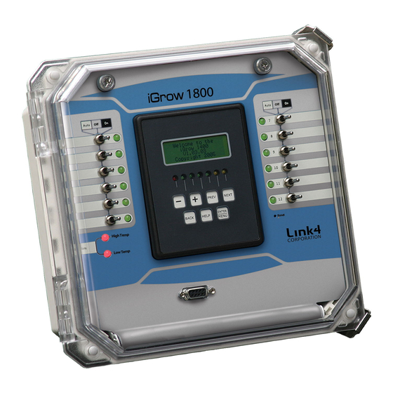
Figure 4.3 Front View of iGrow 1600/1800 Note: There are convenient white spaces provided next to each of the switches to allow for easy equipment labeling. iGrow 1800 Installation Guide Page12 Link4 (714) 524-0004... -
Page 17: Opening The Igrow 1800
1. First, open the clear hinged door by unlatching the two pull latches. 2. Now, loosen the two thumb screws until the iGrow 1800 ‘s front panel comes out. 3. The front panel has a unique design that allows it to swing downward. It can be stopped at two positions: fully downward 180 deg or at 90 deg. -
Page 18: Internal Layout
Making any additional holes in the top, sides, or back of the enclosure can result in water condensation inside the unit, causing damage to the controller. Failure to install to Link4’s specification will void the warranty. In preparation for the control wiring you should decide the iGrow 1800 output assignments and control strategy. -
Page 19: Power Supply Installation
8. Do the same and connect the 12V power lead (RED) to the 12 V terminal using a #0 flat drive screwdriver. 9. Now, if you want you can plug in the power to navigate through the iGrow 1800 or you can continue to install different outputs or inputs, but if you continue, remember to keep the power supply unplugged. - Page 20 Figure 4.7 Wiring the Power Supply iGrow 1800 Installation Guide Page16 Link4 (714) 524-0004...
-
Page 21: Output Installation
Figure 4.9. The board mounted relays are intended as “pilot” relays. For most loads you will want the iGrow 1800 outputs to control a load relay or contactor that is connected to the motor. However, in some cases such as irrigation valves that are 24 VAC, you can drive them directly assuming that you are wiring only one or two valves per relay. - Page 22 Figure 4.8 Output Wiring Example, Wet Contact iGrow 1800 Installation Guide Page18 Link4 (714) 524-0004...
- Page 23 Figure 4.9 Output Wiring Example, Dry Contact iGrow 1800 Installation Guide Page19 Link4 (714) 524-0004...
- Page 24 Figure 4.10 Output Wiring Example, Combination Wet and Dry Contact iGrow 1800 Installation Guide Page20 Link4 (714) 524-0004...
-
Page 25: Hardware Interlock Jumpers
If you want to manually override a vent, curtain or two speed fan, put both switches in the Off position prior to switching On one of the switches. iGrow 1800 Installation Guide Page21 Link4 (714) 524-0004... - Page 26 Figure 4.11 Output Wiring Example, Wet Interlocked Pair iGrow 1800 Installation Guide Page22 Link4 (714) 524-0004...
- Page 27 Figure 4.12 Output Wiring Example, Dry Interlocked Pair iGrow 1800 Installation Guide Page23 Link4 (714) 524-0004...
-
Page 28: Indoor Air Temperature And Humidity Sensor
4. You may extend the sensor cable as needed, but make sure to use an adapter and wire approved by Link4 to make any extensions (the wire and adapter can be purchased from Link4). Any extension wire must be shielded and stranded 24AWG type wire. - Page 29 Figure 4.13 Wiring Indoor Temp/Humidity Sensor iGrow 1800 Installation Guide Page25 Link4 (714) 524-0004...
-
Page 30: Light Sensor
Light Sensor Link4 offers two types of light sensors; Solar and Quantum. The Solar Light Sensor is sensitive to the visible light spectrum, whereas the Quantum version limits the light measurement to the 400 to 700 nanometer band where photosynthesis takes place (PAR). Whichever type you’ve chosen, the installation only varies slightly. - Page 31 Figure 4.14a Wiring Solar Light Sensor iGrow 1800 Installation Guide Page27 Link4 (714) 524-0004...
- Page 32 Figure 4.14b Wiring Quantum Light Sensor iGrow 1800 Installation Guide Page28 Link4 (714) 524-0004...
-
Page 33: Wind Direction And Wind Speed (Anemometer)
4. You may extend the sensor cable to a maximum length of 150, but make sure to use an adapter and wire approved by Link4 to make any extensions (the wire and adapter can be purchased from Link4). 5. Carefully insert the cable through the right most watertight fittings at the bottom of the enclosure. It is easy to strip insulation and/or break wires when pulling cable. - Page 34 1800 Installation Guide Page30 Link4 (714) 524-0004...
-
Page 35: Rain Sensor (Tipping Bucket)
4. You may extend the sensor cable as needed, but make sure to use an adapter and wire approved by Link4 to make any extensions (the wire and adapter can be purchased from Link4). 5. Carefully insert the cable through the right most watertight fittings at the bottom of the enclosure. - Page 36 Figure 4.16 Wiring Rain Sensor iGrow 1800 Installation Guide Page32 Link4 (714) 524-0004...
-
Page 37: Precipitation Sensor (Fast Response)
4. You may extend the sensor cable as needed, but make sure to use an adapter and wire approved by Link4 to make any extensions (the wire and adapter can be purchased from Link4). 5. Carefully insert the cable through the right most watertight fittings at the bottom of the enclosure. - Page 38 Figure 4.16a Wiring Precipitation Sensor iGrow 1800 Installation Guide Page34 Link4 (714) 524-0004...
-
Page 39: Outdoor Air Temperature Sensor
4. You may extend the sensor cable as needed, but make sure to use an adapter and wire approved by Link4 to make any extensions (the wire and adapter can be purchased from Link4). 5. Carefully insert the cable through the right most watertight fittings at the bottom of the enclosure. It is easy to strip insulation and/or break wires when pulling cable. - Page 40 1800 Installation Guide Page36 Link4 (714) 524-0004...
-
Page 41: Co 2 Sensor
4. You may extend the sensor cable as needed, but make sure to use an adapter and wire approved by Link4 to make any extensions (the wire and adapter can be purchased from Link4). 5. Carefully insert the cable through the right most watertight fittings at the bottom of the enclosure. - Page 42 Figure 4.18 Wiring CO Sensor iGrow 1800 Installation Guide Page38 Link4 (714) 524-0004...
-
Page 43: Bottom Heat Probes
4. You may extend the sensor cable as needed, but make sure to use an adapter and wire approved by Link4 to make any extensions (the wire and adapter can be purchased from Link4). 5. Carefully insert the cable through the right most watertight fittings at the bottom of the enclosure. It is easy to strip insulation and/or break wires when pulling cable. - Page 44 Figure 4.19 Wiring Bottom Heat Probe iGrow 1800 Installation Guide Page40 Link4 (714) 524-0004...
-
Page 45: Wiring Sensaphone
3. Run the free end of the cable to the controller unit. 4. You may extend the cable as needed, but make sure to use an adapter and wire approved by Link4 to make any extensions (the wire and adapter can be purchased from Link4). - Page 46 Figure 4.20 Wiring Sensaphone iGrow 1800 Installation Guide Page42 Link4 (714) 524-0004...
-
Page 47: Expansion Units & Multi-Zone Network
It sets the time & date for all iGrow1800s in the network Wiring - Plan for the first installed iGrow 1800™ to be the Site Master. Once all units are installed in their proper locations and all sensors tested, you are ready to connect the serial cable Regardless of which units will be Zone Masters or Expansion units, all units must be wired together in a serial fashion as shown in figure 4.21. - Page 48 Figure 4.21 Wiring Serial Network iGrow 1800 Installation Guide Page44 Link4 (714) 524-0004...
- Page 49 Connecting to a PC To connect your iGrow1600/1800 to a PC, please see Figure 4.22 Figure 4.22 Connecting to a PC iGrow 1800 Installation Guide Page45 Link4 (714) 524-0004...
-
Page 50: Programming Your Igrow1800
Programming your iGrow 1800 Before You Begin Programming Before the iGrow 1800™ is programmed, it is recommended that the following steps are followed: Hardware is properly installed and tested with manual switches. All toggle switches have been restored back to the OFF state. -
Page 51: Status Screens And Programming Screens
Status Screens Welcome Screen Upon power up or a hardware reset (see Reset Controller for more information), the iGrow 1800™ will briefly display the Welcome screen below. After 5 seconds, the iGrow 1800™ will automatically display the Main Status screen. -
Page 52: Main Status Screen
Section), the DH1 status indicator can cycle between DH1 and dh1, indicating that the dehumidification process is on and off, respectively. The last line displays the current time, day of the week and date at the bottom of the screen. iGrow 1800 Installation Guide Page48 Link4 (714) 524-0004... - Page 53 1800 Installation Guide Page49 Link4 (714) 524-0004...
-
Page 54: Sensor Status Display
You can have up to 5 temperature probes attached to your iGrow1800. By mapping your Input Settings, you can assign each probe to whichever Temp Probe Reading (Temp1, Temp2, etc.) that you want. iGrow 1800 Installation Guide Page50 Link4 (714) 524-0004... -
Page 55: Equipment Status
Avg Min Max OutT This screen displays the average, min, and max of InT (Inside Temperature), Hum (Humidity), and OutT (Outdoor Temp) from yesterday. Yesterday is defined as 5:00AM (yesterday) to 4:59AM (today). iGrow 1800 Installation Guide Page51 Link4 (714) 524-0004... -
Page 56: Programming Screens
Setup Deadbands Setup Location Outputs Control VPD Settings Cyclic Lighting Setup Inputs Setup Accumulators Input Multipliers Calibrate Inputs Time/Date & History System Units Communications Fallback Settings Advanced Settings Smart Cool Factors Clear History iGrow 1800 Installation Guide Page52 Link4 (714) 524-0004... -
Page 57: Cool/Heating Stages
This is the number of degrees that the bottom heat temperature must rise above the bottom heat temperature setpoint or threshold before the heat valve switches off. Typical values might be 1 degree F or less. Setup Location iGrow 1800 Installation Guide Page53 Link4 (714) 524-0004... -
Page 58: Outputs Control
34 N Longitude 118 W The iGrow 1800™ has an internal astronomical clock. By knowing the actual coordinates, sunrise and sunset times can be precisely calculated. Go to www.heavens-above.com to find coordinates for your precise location. If a negative longitude is given you are west, and if a negative latitude is given you are south. - Page 59 In this Sequential mode the overall cycle time is equal to the Start Delay + Sum of all light channel On Times + Finish Delay. During the Start Delay and Finish Delay times, all the lights are off so this is in effect the Off Time. iGrow 1800 Installation Guide Page55 Link4 (714) 524-0004...
- Page 60 In the Concurrent mode, all the channels will come on at the same time. Typically, the Start Delay will be set to 0:00 and the Finish Delay will become the Off Time. See Diagram below: iGrow 1800 Installation Guide Page56...
-
Page 61: Setup Inputs (Sensor Mapping)
Setup Inputs is where you tell your iGrow1600/1800™ what sensors you are using (this is also called sensor mapping). The screen above shows the typical sensor mapping for each sensor. If you don’t have a particular sensor then leave the setting as None. iGrow 1800 Installation Guide Page57 Link4 (714) 524-0004... - Page 62 The software value can be modified through the Calibration Inputs screen below. The Backup Sensor is an optional way to tell the iGrow 1800™ which sensor it should default to in the case of a failure on the InTemp temperature sensor.
-
Page 63: Calibrate Inputs
This option lets you choose how often the controller will log sensor and equipment history information. In this case it saves log history every minute, but can be changed to different lengths of time. If you put 00:00, then it will save information every second. iGrow 1800 Installation Guide Page59 Link4 (714) 524-0004... -
Page 64: System Units
Main Status screen) to save your changes. • Local setpoints are the setpoints on the Zone Master itself • Remote setpoints are the setpoints of the Site Master Unit iGrow 1800 Installation Guide Page60 Link4 (714) 524-0004... -
Page 65: Fallback Settings
Note: Once you setup the Site Master, Zone Master(s) and Expansion Unit(s), you should label the front panel on each unit for easier reference in the future. Fallback Settings Fallback Sensor Enabled High Alarm Disabled Force to NORM Sensor iGrow 1800 Installation Guide Page61 Link4 (714) 524-0004... -
Page 66: Advanced Settings
In case of a Fallback failure scenario, or if Fallback is Disabled, the third level of safety is to force the iGrow 1800 into any stage automatically. In the example screen above, the iGrow 1800 would engage whatever equipment you have assigned to be ON under NORM conditions. - Page 67 Time the iGrow1800 will wait to switch from one equipment to the next Error Report This is for diagnostic purposes and it is advisable to contact Link4’s technical support for more details. Comm Diag Scrn By toggling this field to Show, a status screen will become visible that allows you to see if this iGrow is...
- Page 68 Loud Vent This applies to a system with Variable Frequency Drive (VFD) fans and vents. When the Loud Vent option is enabled, there will be no zone temperature/stage change updates while the iGrow 1800 Installation Guide Page64 Link4 (714) 524-0004...
-
Page 69: Clear History
Note: Smart Cool Factors are settings related to how quickly your greenhouse heats up and cools down. The iGrow 1800 allows you to adjust the Smart Cool Factors, but it is NOT RECOMMENDED TO CHANGE THE DEFAULT SETTINGS. To use Smart Cool, you should only adjust the 1-10 values found in the Smart Cool Settings panel. -
Page 70: Setpoint/Time Period Programming
Astronomic Adjustment based on the latitude and longitude entries that you made as shown in the Setup Location portion of this manual. By pressing the + key at the Start Time entry, you will get the following: Press + once = SRise Press + twice = SSet iGrow 1800 Installation Guide Page66 Link4 (714) 524-0004... - Page 71 For example, if the outdoor temperature falls below x ºF, you may want to boost the heat temp setpoint by y degrees. iGrow 1800 Installation Guide Page67 Link4 (714) 524-0004...
- Page 72 Drive to Average will adjust the night setpoints so as to maintain an overall daily average target temperature. Influence Factor Drive to Average Selecting Drive to Average brings you to the following screen iGrow 1800 Installation Guide Page68 Link4 (714) 524-0004...
-
Page 73: Programming Equipment
Smart Cool Settings Setpoint Alarms Auxiliary Controls Expansion Settings Heat Demand Cool Demand After you press the Enter/Menu button you will get the following screen, if this is the first time programming this channel. iGrow 1800 Installation Guide Page69 Link4 (714) 524-0004... - Page 74 VOut – VOut is a variable voltage or current output for equipments such as variable speed fans. This option only appears if you have installed the optional iMOD (Multi-Output Device) expansion board. iGrow 1800 Installation Guide Page70 Link4 (714) 524-0004...
-
Page 75: On/Off Equipment
This second screen can be programmed for various applications which we will discuss below. ExFan OnOff No Pump AC Override Disabled For now we will leave the default, No Pump and leave the Active Cooling (AC) Override Disabled. iGrow 1800 Installation Guide Page71 Link4 (714) 524-0004... -
Page 76: Irrigation Programming
Mode. Pressing the + or – keys cycles you through the mode choices. There are six choices defined as follows: Scheduled This mode is like a time clock where you set the start time, run time and days of the week. Accumulated Light iGrow 1800 Installation Guide Page72 Link4 (714) 524-0004... - Page 77 Scheduled Days Scheduled mode allows the iGrow 1800™ to turn the Irrigation channel on for a duration equal to OnTime at up to six start times per day. Use Off to indicate unused time slot. The third screen allows for enabling or disabling scheduled irrigation for an entire day.
- Page 78 6000 W/m2h 55°F 3500 W/m2h 85°F Max Off 8:00 hh:mm S2 = 3.5 kW/m2 at 55°F The crosshairs represent the irrigation trigger point. This location will change as the actual temperature changes iGrow 1800 Installation Guide Page74 Link4 (714) 524-0004...
- Page 79 Sunrise or Sunset. You can cycle through the three options by pressing the + key when the cursor is over the at. The Cycle Time is the combination of the On time and the Off time added together. Trigger Irrigation iGrow 1800 Installation Guide Page75 Link4 (714) 524-0004...
- Page 80 09:00A 07:00P Trigger The iGrow 1800™ enables the external trigger only between the Start and End times. These two time values can be astronomically adjusted with respect to either sunrise or sunset. Soil Trigger Irrigation The Soil Trigger irrigation option is designed to turn on your irrigation valve(s) from an input threshold being reached.
- Page 81 Max Off 00:00 hh:mm The third and final screen is where you select the VPD threshold for turning on the irrigation valve. The threshold is an accumulated pressure measurement input as in HG-Hr . iGrow 1800 Installation Guide Page77 Link4 (714) 524-0004...
-
Page 82: Co2 Equipment
09:00A 07:00P The iGrow 1800™ can also be used to regulate the amount of CO inside the greenhouse by controlling CO pumps or injectors. This mode is active between the Start and End times. You have the option of controlling the Start and End times based on a fixed time window or a relative time window. -
Page 83: Light (Hid) Equipment
First you will program the light level below which the lights will be turned ON. Then you will program the level at which they will be turned off. The final parameter is the Time Delay. If the sun were to appear momentarily, you iGrow 1800 Installation Guide Page79... - Page 84 A “0” means the lights won’t come on for that entire day, a “1” means they will. Once you’ve pressed the Enter button, move the cursor with the Next or Prev keys. You toggle between the 0 and the 1 with the + key. Cyclic Light control Light Select Operational Mode: Cyclic iGrow 1800 Installation Guide Page80 Link4 (714) 524-0004...
- Page 85 0. If your threshold is not reached by the Turn On Time (shown as 3 PM in the screen), then the light will turn on and remain on until either the Light Threshold is reached or the Day End time is reached. MZone (Micro-Zone) for ON/OFF Equipment iGrow 1800 Installation Guide Page81 Link4 (714) 524-0004...
- Page 86 The iGrow 1800™ can be used to monitor and control up to five (5) independent heating or cooling “Micro- Zones”. What is a Micro-Zone? A Micro-Zone is a region or compartment within a greenhouse that has a different temperature setpoint. Typical uses for Micro-Zones would be bench heating, corridor heating, or any other area in the greenhouse with separate heating or cooling equipment.
-
Page 87: Pump Control
When you have a mixvalve type heating system, it is often necessary for the controller to manage the system pump(s). The iGrow 1800™ can control up to 5 Pumps, each one being activated when the mixvalve tied to it opens beyond the Minimum threshold. - Page 88 Similar to the Light override, you can also override the nutrient setpoint if the greenhouse temperature goes above the threshold you set. Pump2 Pump ON TIME 0sec OFF TIME 5sec ON/OFF TIME iGrow 1800 Installation Guide Page84 Link4 (714) 524-0004...
-
Page 89: Vent (Proportional) Programming
Wind Overrides Wind overrides limits are important for safe and effective vent operation. Of course, a weather station (or Link4 anemometer) must already be installed to use this feature. First you have to set Dir, which is the direction that the vent faces when open. - Page 90 Position Sensor The iGrow 1800 offers the ability to read true vent position if you’ve wired a vent position sensor to your iGrow1800. This field sets which Position Sensor to look at (that you have defined in your Menu Mapping).
-
Page 91: Curtain Programming
In programming your curtain for shading you will first set a close and open time. It is during this window of time that you permit or enable the curtain to be controlled for shading purposes. 09/10 H1Top Curt SHADING Close __at__ 7:00A Open 6:00P iGrow 1800 Installation Guide Page87 Link4 (714) 524-0004... - Page 92 Curtains are often used as a thermal blanket during the night. We call this energy control. On the first screen you set the Close and Open time window. As above, you have the option of adjusting the Close and Open times for Sunset and Sunrise. iGrow 1800 Installation Guide Page88 Link4 (714) 524-0004...
-
Page 93: Mixing Valves
Since you can have up to 5 temp probes connected to your iGrow1600/1800 be sure to set this to the correct one. Use the + or – buttons to select the correct probe. iGrow 1800 Installation Guide Page89... - Page 94 Mixvalve. In this example, if the return water temperature is below 105°F then the mixvalve will only open 5% until the return temperature reaches the low temperature setpoint of the supply water temperature. iGrow 1800 Installation Guide Page90 Link4 (714) 524-0004...
- Page 95 Be very careful when increasing this number. Disable Disable stops the zone feedback loop used by the PID control. iGrow 1800 Installation Guide Page91 Link4 (714) 524-0004...
-
Page 96: Pzone (Micro-Zone) For Proportional Equipment
PID controls. If you feel a change is necessary and are not sure how to proceed contact your local distributor, or Link4 directly, for assistance. Note: You can also disable the zone temperature control loop. This is useful if you want to set a fixed water temperature. - Page 97 For PID control of the PZone the two following pages must be activated. To activate these pages go to the System Setup screen and then the Advanced Settings menu and set MixValve Param from Hide to Show. iGrow 1800 Installation Guide Page93...
- Page 98 Note: The iGrow1600/1800’s default settings for PID should be suitable for most any installation, and therefore should not be modified without a good understanding of PID controls. If you feel a change is necessary and are not sure how to proceed contact your local distributor, or Link4 directly, for assistance. 07/08...
-
Page 99: Vout Variable Voltage/Current Output
Generic PID Controller (G PID) The iGrow 1800 supports two types of Generic PID controllers: Timed and Pulsed. The timed version requires two output channels and the first channel must be on an odd numbered output. The pulsed version requires only one output and can be set on any channel. - Page 100 Min is the heat demand percentage that you want the minimum output level to occur at. The value to the right of Min sets the current output that occurs at the min percentage. VFan1 VOut Offset Cal 0.00 Gain 1.00 Offset Cal Gain Cal iGrow 1800 Installation Guide Page96 Link4 (714) 524-0004...
-
Page 101: Dehumidify/Humidify
DHLT is the dehumidification state that is engaged when the outside temperature is below a user set value on the next screen (in the example, when the outside temperature is less than 35.0ºF). H or humidify stage is engaged when zone’s humidity is below the ‘Low’ Humidity Setpoint iGrow 1800 Installation Guide Page97 Link4 (714) 524-0004... -
Page 102: Stage Overrides
Stage overrides are useful for testing purposes, where you can force the iGrow1600/1800 into any of the heating or cooling stages. They are also useful for fumigation, where there are spraying cycles the require everything to be closed and then exhaust cycle where air exchange takes place. iGrow 1800 Installation Guide Page98 Link4 (714) 524-0004... -
Page 103: Equipment Overrides
This programming feature allows you to manually override your greenhouse equipment for specified periods of time, either once or daily. Select the Channel Pressing the + or - to find the Channel you wish to override. iGrow 1800 Installation Guide Page99 Link4 (714) 524-0004... -
Page 104: Smart Cool Settings
Pressing the + key when the upper right hand field is highlighted, toggles you between the “Enable” and “Disable” Smart Cool option. If you toggle to the “Enable” option your greenhouse will now function under “Smart Cool”. Smart Cool Setting (1 to 10) iGrow 1800 Installation Guide Page100 Link4 (714) 524-0004... - Page 105 This change will occur gradually. Similarly, as the outside temperature goes above the inside setpoint temperature, the upstage time is reduced and the downstage time is increased. iGrow 1800 Installation Guide Page101 Link4 (714) 524-0004...
-
Page 106: Setpoint Alarms
The Time Value that must be met in order to trigger the alarm. A value of 99 disables the alarm. If the value is zero, then the alarm will occur immediately when the temp setting is met. Note: It is highly recommended you use the optional Link4 Sensaphone to call your user preset phone numbers in case of an alarm being triggered. -
Page 107: Expansion Settings
Output Channel 3 will turn on. Channel 3 will then remain active for 10 minutes or until the temperature rises above 59°F. This is useful to prevent cycling of equipment. Expansion Settings Expansion Settings Enabled CH15 Voltage CH16 Voltage Expansion Settings AnalogIn1 Voltage AnalogIn2 Voltage iGrow 1800 Installation Guide Page103 Link4 (714) 524-0004... -
Page 108: Heat Demand
OLight Factor is a percentage of the outdoor light influence on determining heat demand. 0% represents no influence, while 100% represents maximum influence. Wind Factor Wind Factor is a percentage of wind’s influence on determining heat demand. 0% represents no influence, while 100% represents maximum influence iGrow 1800 Installation Guide Page104 Link4 (714) 524-0004... -
Page 109: Cool Demand
When Cool Demand fall below this percentage, the greenhouse will enter passive cooling. Note - When the iGrow first starts, if cool demand is less than the active cool setting, the greenhouse will be in passive cooling. iGrow 1800 Installation Guide Page105 Link4 (714) 524-0004... -
Page 110: Appendix - Advanced Auxiliary Controls
cccccccccccccccccccccccccccccc... - Page 111 Appendix iGrow 1800™ User Manual Supplement Advanced Auxiliary Controls User’s Manual October 2015 Edition - Version 1.0...
- Page 112 Getting Started with Auxiliary Controls ..................109 Typical Conditional Statement ......................112 Example of Conditional Statement Priorities ................116 2 OPERATOR CONDITIONAL STATEMENT ..................119 Using Variables in Control Statements ..................122 iGrow 1800 Advanced Aux Controls Page 107 of 131 Link4 (714) 524-0004...
-
Page 113: What Are Advance Auxiliary Controls
What are Advance Auxiliary Controls? Link4’s iGrow 1800 is an industry leading advance climate control system. Out of the box it has many built-in equipment logic to optimize your ability to easily control and shape the environment as desired to optimize plant growth, yield, and quality while minimize inputs such as labor, energy consumption, water, nutrient, etc. - Page 114 Locate the Zone Settings control box in the lower left. Select “Aux Controls”. This will bring up the Advanced Aux Controls window. On the iGrow 1800, there will always be a Zone Master control unit in a zone. Sometimes, there could other “expansion” units (up to 3).
- Page 115 (if x condition then result y). Select Edit to customize the logic on this statement to suit your control needs. iGrow 1800 Advanced Aux Controls Page 110 of 131 Link4 (714) 524-0004...
-
Page 116: Typical Conditional Statement
The action hold time is the time that the ACTION will continue to be performed even though the conditional statement is no longer met (FALSE). USER COMMENT: Useful comments for user to describe the intended use of the conditional statement. iGrow 1800 Advanced Aux Controls Page 111 of 131 Link4 (714) 524-0004... - Page 117 First, select the operands, by clicking on the None button. The operands are grouped by functions. For inside temperature, go to the Sensor group. Then select Inside Temperature. Next select the “greater” operator ( > ) iGrow 1800 Advanced Aux Controls Page 112 of 131 Link4 (714) 524-0004...
- Page 118 Select “Number/Value” and enter in 87.5. Note the degree Farenheit is inserted automatically since the AAC knows that you are comparing with the Inside Temperature reading. iGrow 1800 Advanced Aux Controls Page 113 of 131 Link4 (714) 524-0004...
- Page 119 As with the operands, the Target Equipment are grouped by functions. In this case, select Equipment and select Curt. This will set the Curtain as the target of this statement. iGrow 1800 Advanced Aux Controls Page 114 of 131 Link4 (714) 524-0004...
- Page 120 AACs. Click Save to save the statement. You could add more statements. However, it is NOT saved until you click the Update button. iGrow 1800 Advanced Aux Controls Page 115 of 131 Link4 (714) 524-0004...
-
Page 121: Example Of Conditional Statement Priorities
(> 1000 W/m2), the Curtain will close regardless of what the Inside Temperature is. However, what if you don’t want this? What if you want the Curtain to open up when it’s too warm inside, regardless of the light level? iGrow 1800 Advanced Aux Controls Page 116 of 131 Link4 (714) 524-0004... - Page 122 Then the new ACCs will look like this: Click Update to save. This will cause the Curtain open up when it’s too warm inside, regardless of light level. iGrow 1800 Advanced Aux Controls Page 117 of 131 Link4 (714) 524-0004...
- Page 123 1800 Advanced Aux Controls Page 118 of 131 Link4 (714) 524-0004...
-
Page 124: Operator Conditional Statement
Continuing from above examples, and add a new control statement: As usual, add an operand, however this time chose the number operand first. Then choose the less than operator iGrow 1800 Advanced Aux Controls Page 119 of 131 Link4 (714) 524-0004... - Page 125 As you can see, a place holder for the second operator is automatically presented. Click on it and select the less than operator. Now add in the 90% for the third operand Then the 10 minute Condition Hold Time iGrow 1800 Advanced Aux Controls Page 120 of 131 Link4 (714) 524-0004...
- Page 126 Then set the Target Equipment and Value If done properly, you should get the conditional statement #3 as shown below: Click Update to save. iGrow 1800 Advanced Aux Controls Page 121 of 131 Link4 (714) 524-0004...
-
Page 127: Using Variables In Control Statements
> 70F, you want to set an alarm. Again, it’s best to try to do this on your own first, then consult the following figures. iGrow 1800 Advanced Aux Controls Page 122 of 131 Link4 (714) 524-0004... - Page 128 First, let’s say the pump is on output #12: First create a variable and call it Main Pipe Water Sensor. Go to the Zone Master Variable tab in the AACs. Name the variable appropriately, with comments. iGrow 1800 Advanced Aux Controls Page 123 of 131 Link4 (714) 524-0004...
- Page 129 Before the variable name can be used, you need to click Update. Exit the AAC panel and come back in again. iGrow 1800 Advanced Aux Controls Page 124 of 131 Link4 (714) 524-0004...
- Page 130 Now use the familiar process to create a new conditional statement #4: iGrow 1800 Advanced Aux Controls Page 125 of 131 Link4 (714) 524-0004...
- Page 131 Then set the value to 1, in the event that Digital Input 1 = ON for 1 minute: Now that we have created statement to set the variable, we can start using it in other statements: Add statement #5, select the variable as the operand: iGrow 1800 Advanced Aux Controls Page 126 of 131 Link4 (714) 524-0004...
- Page 132 It’s worth noting that statement #5 is an example of Zero Operator Statement. We did not enter any operator in the process. Now we use the variable to turn on some HAF (horizontal airflow fans): iGrow 1800 Advanced Aux Controls Page 127 of 131 Link4 (714) 524-0004...
- Page 133 Setting the alarm based on a combination of water present and water temperature is a bit more complex. First, detect if the water is present: Then choose the AND operator iGrow 1800 Advanced Aux Controls Page 128 of 131 Link4 (714) 524-0004...
- Page 134 Now build the temperature conditional statement: Now set the action to turn the alarms on: iGrow 1800 Advanced Aux Controls Page 129 of 131 Link4 (714) 524-0004...
- Page 135 The completed statements should look like below: Click Update to save. Now, as example of debugging, there is actually a problem with the above construction. Can you find it? iGrow 1800 Advanced Aux Controls Page 130 of 131 Link4 (714) 524-0004...
- Page 136 Now, when there’s no water, the variable will be set to 0. Without #5, this variable goes to 1 to indicate water present, but still stay as 1 eventhough the sensor detects that the water is gone. iGrow 1800 Advanced Aux Controls Page 131 of 131...
Need help?
Do you have a question about the iGrow 1800 and is the answer not in the manual?
Questions and answers