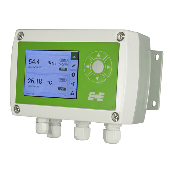
E+E Elektronik EE310 Operating Manual
Humidity/temperature transmitter
Hide thumbs
Also See for EE310:
- Operation manual (36 pages) ,
- Operation manual (44 pages) ,
- User manual (48 pages)
Table of Contents
Advertisement
Quick Links
Download this manual
See also:
Operating Manual
Advertisement
Table of Contents

Related Manuals for E+E Elektronik EE310


Summary of Contents for E+E Elektronik EE310
- Page 1 Operation manual EE310 Humidity/Temperature Transmitter BA_EE310_e // V1.5 // Technical data subject to change // 194474...
-
Page 2: Fcc Notice
E+E Elektronik® Ges.m.b.H. provides no warranty of any kind for this publication and accepts no liability for improper use of the products described. This publication might contain technical inaccuracies or typographical errors. The content is revised regularly and is not subject to change management. The manufacturer reserves the right to modify or change its described products at any time. -
Page 3: Table Of Contents
6.2 Cleaning the sensing head / filter replacement ...................25 Sensor replacement ............................25 RH / T adjustment and calibration .......................26 Scope of supply ..........................27 Replacement parts / Accessories ....................27 Technical data ............................28 10 Appendix ............................29 10.1 Appendix A ..............................29 Operating instructions for EE310 Humidity / Temperature Transmitter... -
Page 4: General
1.2.2. Alarm module with voltages >50 V (option AM2) The optional alarm module is isolated from the low-voltage side of EE310 by a special partition; this must remain fitted at all times in the bottom part of the enclosure. The EE310 enclosure must be tightly closed during operation. An open enclosure corresponds to IP00 and exposes components carrying dangerous voltage. -
Page 5: Product Description
Product Description EE310 is optimised for reliable measurement in demanding industrial applications. In addition to highly accurate measurement of relative humidity (RH) and temperature (T), the transmitter also calculates parameters such as dew point, absolute humidity and mixing ratio. Various models are available including wall, duct and remote probe. The remote probe can be used up to 180 °C... -
Page 6: Models
Space for optional modules Fig. 2 Modular enclosure Models EE310 is available for wall or duct mount as well as with various remote probes. The remote probes can be employed up to 180 °C and 20 bar (356 °F) (300 psi) T1: Wall mounting T5: Remote probe up to 180 °C... -
Page 7: Installation
• Mount the two DIN rail brackets (to be ordered separately, see chapter 8 Replacement parts / Accessories) onto the back side of the enclosure. • Snap in the enclosure onto the DIN rail Fig. 5 DIN rail installation Operating instructions for EE310 Humidity / Temperature Transmitter... -
Page 8: Electrical Connection
Check output scale after changing between voltage and current output. 3.2.2 Plug options Option E4 GND Output OUT 2 OUT 1 power supply + analogue output Option E5 GND RS485 (shielded) n.c. RS485 B (=D-) Operating instructions for EE310 Humidity / Temperature Transmitter n.c. RS485 A M16x1.5 (=D+) - Page 9 E+E Service. National regulations for installation shall be observed. External diameter of the cable for Modbus RTU female plug: 4 - 6 mm (0.16 - 0.24”) Maximal wire cross section for connecting cable: 0.5 mm² (AWG 21) Operating instructions for EE310 Humidity / Temperature Transmitter...
-
Page 10: Probe Mounting
T working range probe: -40...+80 °C (-40...176 °F) electronics -40...+60 °C (-40...140 °F) -20...+50 °C (with display) (-4...122 °F) The probe shall be horizontal or point downwards. Fig. 9 Mounting of model EE310-T2 Operating instructions for EE310 Humidity / Temperature Transmitter... -
Page 11: T5: Remote Probe Up To 180 °C (356 °F)
3.3“ condense water the probe shall be avoided hanging probe probe into separation wall Fig. 10 Mounting the remote probe of EE310-T5 Operating instructions for EE310 Humidity / Temperature Transmitter... -
Page 12: T10: Pressure Tight Probe Up To 20 Bar (300 Psi)
(±72 °F) operation. Replace the metal sealing ring (see Fig. 12 Installation of the EE310-T10 probe directly into the process) by a new one every time before re-installing the probe. Probe installation steps • Close both valves. -
Page 13: Installation Of The Probe With Ball Valve Set
(0.55”) stop valve stop valve Fig. 12 Installation of the EE310-T10 probe directly into the process Installation of the probe with ball valve set The ball valve set allows for installation and removal of the probe without process interruption. For mounting into a duct, the ball valve shall be installed perpendicular to the flow direction. - Page 14 • After the probe has been pushed out of the process up to the stop, close the ball valve. • Remove the probe from the ball valve. Observe the correct positioning of the sealing element 1 before reinstalling the probe. Operating instructions for EE310 Humidity / Temperature Transmitter...
-
Page 15: Optional Modules
Example hysteresis mode % / RH Switching point 2 Hysteresis 2 Switching point 1 Hysteresis 1 open Terminal 1-2 / 4-5 closed open Terminal 2-3 / 5-6 closed Fig. 16 Example window mode Operating instructions for EE310 Humidity / Temperature Transmitter... - Page 16 Dew point [K] Hysteresis Frost point [K] Volume concentr. [ppm] Standard Normal state Inverted Standard Error indication Normal state Inverted * Menu only available with connected alarm module during EE310 start-up Operating instructions for EE310 Humidity / Temperature Transmitter...
-
Page 17: Power Supply Module (Option Am3)
Power supply module (option AM3) This module allows the EE310 to be powered with 100...240 V AC (50/60 Hz), 2 V A. Fig. 18 Power supply module (option AM3) Plug connections for option AM3 see chapter 3.2.2 Plug options. The AM3 option includes a 1.25 A fuse on the 100-240 V side. This fuse may not be replaced by the user, but only by the E+E Service. - Page 18 None Parity Even Stop bits value value Address * Menu only available with connected Modbus RTU module during EE310 start-up. Data transmission Factory settings Selectable values Baud rate 9600 300, 600, 1200, 2400, 4800, 9600, 19200, 38400, 57600, 76800 Data bits...
-
Page 19: Pluggable Probe (Option Pc4)
Pluggable probe (option PC4) EE310-T5 and EE310-T10 transmitters are optionally available with pluggable sensing probe, which is attached to the EE310 enclosure by a push-pull plug. If the probe or the probe cable gets damaged it is possible to easily replace the probe without humidity and temperature adjustment. -
Page 20: Operation
Status LEDs are located at the USB port 3.5” TFT Colour Display (optional) The EE310 display includes a data logger and push buttons for full configuration of the device. Upon start-up of an EE310 with display, the data logger and the configuration menu will be initialised during the first 5 seconds. Chart + data logger Configuration menu Status information Buzzer ON / OFF Error indication / information Fig. 23 Display with push buttons Operating instructions for EE310 Humidity / Temperature Transmitter... -
Page 21: Chart + Data Logger
Water activity [aw] Saturation [%] Axis 2 Scale minimum value Water content [ppm] Wet bulb temp. [K] Dew point [K] Scale maximum value Frost point [K] Volume concentr. [ppm] Delete saved values Operating instructions for EE310 Humidity / Temperature Transmitter... - Page 22 Each point in the graph represents a logged value. The points are connected by a linear interpolation. One point The data logging continues even when the data memory is full; new data is stored while the oldest data is deleted (first in first out memory). The last 20.000 logged values are available in the internal memory. The logged data can be downloaded with EE-PCS Product Configuration Software as .csv file by choosing the measurands and the time period. Operating instructions for EE310 Humidity / Temperature Transmitter...
-
Page 23: Configuration Menu
- language | date, time | parameters | password protection Status status and device information * Menu only available with connected corresponding modules. Status information The status information shows all actual EE310 settings. Fig. 25 Status information Buzzer ON / OFF Buzzer ON... -
Page 24: Maintenance
LED 1 (blue): analogue output is set to voltage. LED 2 (orange): analogue output is set to current. LED 3 (flashing green): supply voltage applied (microprocessor is active). LED 4 (red): constant lit: error category 1 flashes: error category 2 Operating instructions for EE310 Humidity / Temperature Transmitter... -
Page 25: Solving Typical Problems
Since the performance of the instrument after the sensor exchange depends on the overall accuracy of the adjustment procedure, it is strongly recommended to return the device to E+E for sensor replacement. Operating instructions for EE310 Humidity / Temperature Transmitter... -
Page 26: Rh / T Adjustment And Calibration
(comparison with a reference) or adjustment (bringing the device in line with a reference). Calibration and adjustment at E+E Elektronik Calibration and/or adjustment can be performed in the E+E Elektronik calibration laboratory. For information on the E+E capabilities in ISO or accredited calibration please see www.eplusecal.com. -
Page 27: Scope Of Supply
Mating plug RKC 5/7 AM3 / E4 / E7 / E12 Mating plug RSC 5/7 (2 pcs. for option E12) E5 / E7 / E12 *) Other languages can be downloaded at www.epluse.com/EE310 Tab. 4 Scope of supply Replacement parts / Accessories see data sheet “Accessories”... -
Page 28: Technical Data
The accuracy was calculated in accordance with EA-4/02 and with regard to GUM (Guide to the Expression of Uncertainty in Measurement). 3) Appropriate for outdoor use, wet location, degree of pollution 2, overvoltage category II, altitude up to 3000 m (9843 ft). Operating instructions for EE310 Humidity / Temperature Transmitter... -
Page 29: 10 Appendix
Water activity [aw] Saturation [%] Axis 2 Scale minimum value Water content [ppm] Wet bulb temp. [K] Dew point [K] Scale maximum value Frost point [K] Volume concentr. [ppm] Delete saved values Operating instructions for EE310 Humidity / Temperature Transmitter... -
Page 30: Display Settings
Reference value Offset Current measured value Reference Rel. humidity Reference value value value low 2 point adjustment Reference value Current measured Temperature high value Calibration status Reset to factory calibration Operating instructions for EE310 Humidity / Temperature Transmitter... - Page 31 Measuring system US units Capacity C76 Humidity coefficient Capacity offset Working pressure Capacity gain Parameters Probe replacement Resistance R0 Temperature coefficient TK Resistance Offset Password protection Activate Code Buzzer Status Status page Device info Operating instructions for EE310 Humidity / Temperature Transmitter...
- Page 32 Frost point [K] Volume concentr. [ppm] Standard Normal state Inverted Standard Error indication Normal state Inverted Modbus settings Baudrate value None Parity Even Stop bits value value Address Fig. 30 Configuration menu Operating instructions for EE310 Humidity / Temperature Transmitter...
- Page 33 11 Notes ......................................................................................................................................................................................................................................................................................................................................................................................................................................................................................................................................................................................................................................................................................................................................................................................................................................................................................................................................................Operating instructions for EE310 Humidity / Temperature Transmitter...
- Page 34 ......................................................................................................................................................................................................................................................................................................................................................................................................................................................................................................................................................................................................................................................................................................................................................................................................................................................................................................................................................Operating instructions for EE310 Humidity / Temperature Transmitter...
- Page 35 ......................................................................................................................................................................................................................................................................................................................................................................................................................................................................................................................................................................................................................................................................................................................................................................................................................................................................................................................................................Operating instructions for EE310 Humidity / Temperature Transmitter...
- Page 36 COMPANY HEADQUARTERS TECHNICAL OFFICES E+E ELEKTRONIK Ges.m.b.H. E+E CHINA www.epluse.com www.epluse.cn E+E ITALY Langwiesen 7 BEIJING www.epluse.it A-4209 Engerwitzdorf Tel: +86 10 84992361 Tel: +39 02 2707 8636 Austria info@epluse.cn info@epluse.it Tel: +43 7235 605 0 SHANGHAI Fax: +43 7235 605 8 Tel: +86 21 61176129 info@epluse.com...
Need help?
Do you have a question about the EE310 and is the answer not in the manual?
Questions and answers