
Related Manuals for Renogy Wanderer 30A


Summary of Contents for Renogy Wanderer 30A
- Page 1 The Traveler Series: Wanderer RENOGY 30A PWM Charge Controller Manual 2775 E. Philadelphia St., Ontario, CA 91761 Version: 2.5 1-800-330-8678...
-
Page 2: Important Safety Instructions
Important Safety Instructions Please save these instructions. This manual contains important safety, installation, and operating instructions for the charge controller. The following symbols are used throughout the manual: WARNING: Indicates a potentially dangerous condition. Use extreme caution when performing this task. CAUTION: Indicates a critical procedure for safe and proper operation of the controller NOTE:... - Page 3 Battery Safety • Do let the positive (+) and negative (-) terminals of the battery touch each other. • Use only sealed lead-acid, flooded, or gel batteries which must be deep cycle. • Explosive battery gases may be present while charging. Be certain there is enough ventilation to release the gases.
-
Page 4: Table Of Contents
Table of Contents General Information......................5 Optional Components ...................... 7 Identification of Parts ....................... 7 Installation ........................8 Mounting Recommendations ..................8 Wiring .......................... 9 Operation ........................11 Setting Battery Type ....................11 LED Indicators ....................... 12 System Status Troubleshooting ..................13 Maintenance ........................ -
Page 5: General Information
General Information The Wanderer is an advanced charge controller for off-grid solar applications. Integrating highly efficient PWM charging, this controller increases battery life and improved system performance. It is exclusively designed for 12V battery banks. The controller is embedded with self-diagnostics and electronic protection functions that prevent damages from installation mistakes or system faults. - Page 6 Bulk Charge: This algorithm is used for day to day charging. It uses 100% of available solar power to recharge the battery and is equivalent to constant current. Boost Charge: When the battery has charged to the Boost voltage set-point, it undergoes an absorption stage which is equivalent to constant voltage regulation to prevent heating and excessive gassing in the battery.
-
Page 7: Optional Components
Optional Components *The Wanderer is shipped with by itself with no additional components. Optional components that require a separate purchase: Remote Temperature Sensor (TS-R): Measures the temperature at the battery and uses this data for very accurate temperature compensation. The sensor is supplied with a 6.6ft cable length that connects to the charge controller. -
Page 8: Installation
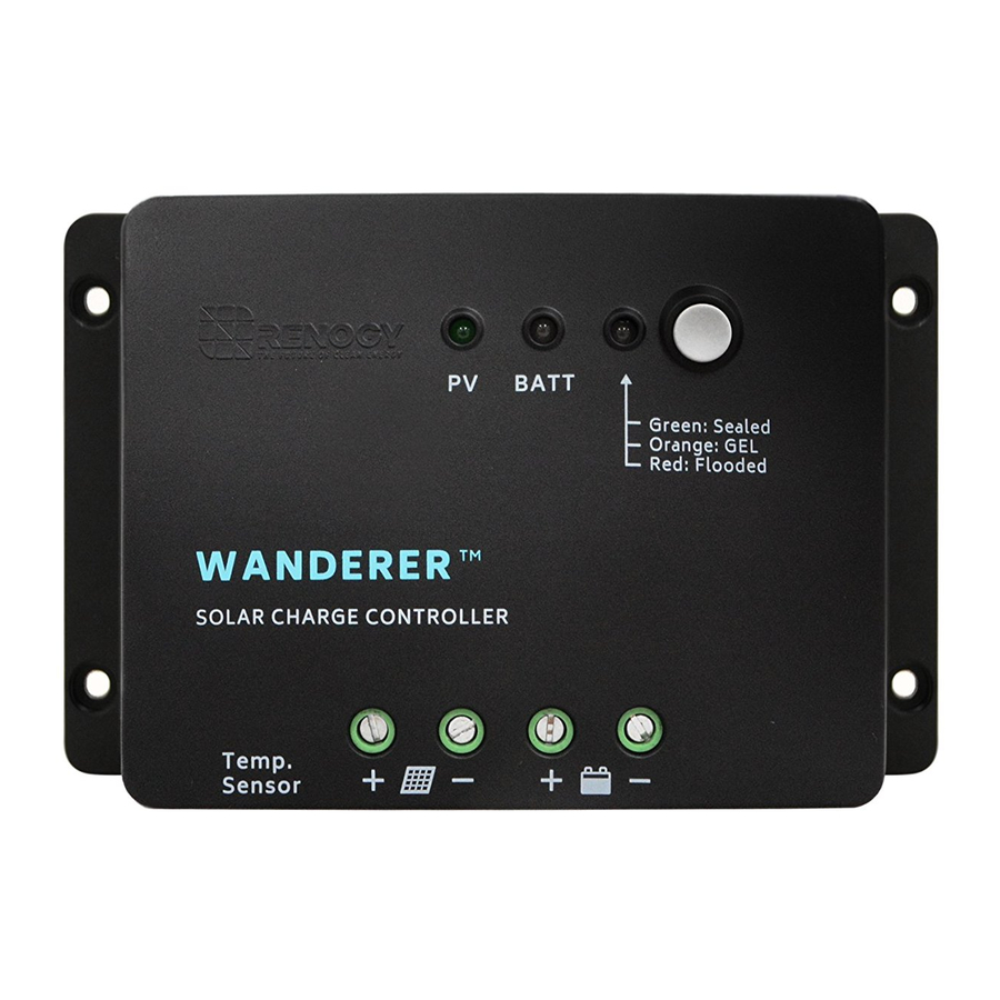
Key Parts 1. Battery Select Button 2. Battery Select Indicator 3. Battery Indicator 4. PV Indicator 5. Remote Temperature Sensor Adapter (Requires separate purchase) 6. PV Terminals 7. Battery Terminals Installation WARNING: Connect battery terminal wires to the charge controller FIRST then connect the solar panel(s) to the charge controller. -
Page 9: Wiring
Wiring 1. Unscrew battery terminals and connect battery connections... - Page 10 2. Unscrew PV terminals and connect PV connections...
-
Page 11: Operation
3. Insert temperature sensor block terminal and connect wires (POLARITY SENSITIVITY DOES NOT MATTER) Operation After connecting the battery to the charge controller, the controller will turn on automatically. Operation of this controller is very simply. Users set the battery type, and leave the rest of the work to the charge controller. -
Page 12: Led Indicators
coded) and simply leave the controller alone until the flashing stops (this should take approximately 10 seconds). This indicates the parameter has been set. NOTE: If the LED lights do not flash, hold the gray button for 7 seconds again, release, and immediately press the gray button again to enable the flashing Set Battery Type Sealed... -
Page 13: System Status Troubleshooting
System Status Troubleshooting Description Troubleshoot Use a multi-meter to verify the rated battery voltage. Disconnect any loads connected to the battery to allow it to Battery is low-voltage charge. Use a multi-meter to check the voltage of the battery. Make sure the battery voltage is not exceeding the rated Battery is over-voltage specification of the charge controller. -
Page 14: Maintenance
Maintenance For best controller performance, it is recommended that these tasks be performed from time to time. 1. Check that controller is mounted in a clean, dry, and ventilated area. 2. Check wiring going into the charge controller and make sure there is no wire damage or wear. -
Page 15: Technical Specifications
Technical Specifications Electrical Specifications Description Parameter Nominal Voltage 12 VDC Rated Charge Current Max. PV Input Voltage 25 VDC Self-Consumption <10mA High Voltage Disconnect Over-Voltage Reconnect Under Voltage Warning ≤15V Charging Limit Voltage Sealed:14.6V; Flooded: 14.8V; Gel: NO Equalization Voltage Sealed: 14.4V;... -
Page 16: Mechanical Specification
163.83 x 109.62 x 44.7mm Dimensions 6.45 x 4.31 x 1.76in IP20 Enclosure Dimensions Renogy reserves the right to change the contents of this manual without notice. For the most up to date manual, visit our download page at www.renogy.com Revision: 9/19/2017...
Need help?
Do you have a question about the Wanderer 30A and is the answer not in the manual?
Questions and answers