Table of Contents
Advertisement
SERVICE MANUAL
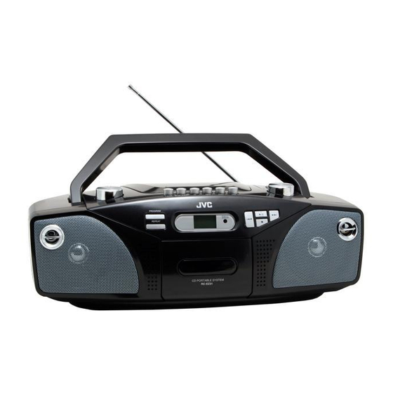
CD PORTABLE SYSTEM
RC-EZ31A
No service part is available for this model.
Based on One to One exchange policy.
Safety precaution ............................................................................ 2
Preventing static electricity ............................................................. 3
Disassembly procedure ................................................................... 4
Flow of function operation until TOC read ...................................... 5
Voltage charts ................................................................................. 6
Block diagram ................................................................................. 8
Wiring connection ........................................................................... 9
Schematic diagrams ...................................................................... 11
Illustration of packing and parts list ............................................... 18
COPYRIGHT © 2006 JVC ASIA PTE LTD
SERVICE POLICY
Contents
No: 28225
JAN. 2006
Advertisement
Table of Contents

Related Manuals for JVC RC-EZ31A


Summary of Contents for JVC RC-EZ31A
-
Page 1: Table Of Contents
Flow of function operation until TOC read ........5 Voltage charts ................. 6 Block diagram ................. 8 Wiring connection ................9 Schematic diagrams ..............11 Illustration of packing and parts list ..........18 COPYRIGHT © 2006 JVC ASIA PTE LTD No: 28225 JAN. 2006... -
Page 2: Safety Precaution
RC-EZ31 Safety Precautions XL-SV320SL/SV305GD XL-SV308BU 1. This design of this product contains special hardware and many circuits and components specially for safety purposes. For continued protection, no changes should be made ti the original design unless authorised in writing by the manufacturer. Replacement parts must be identical to those used in the original circuits. -
Page 3: Preventing Static Electricity
RC-EZ31 Preventing static electricity Electrostatic discharge (ESD), which occurs when static electricity stored in the body, fabric, etc. is discharged, can destroy the laser diode in the traverse unit (optical pcikup). Take care to prevent this when performing repairs. 1.1. Grounding to prevent damage by static electricity Static electricity in the work area can destroy the optical pickup (laser diode) in devicessuch as DVD players. -
Page 4: Disassembly Procedure
RC-EZ31 Disassembly Procedure XL-SV320SL/SV305GD XL-SV308BU Remove the back cabinet Screw A 1. Open battery cover and remove 3 screws on the bottom cabinet. (Screw A) 2. Remove 5 screws on back (Screw B) Screw B Remove the top panel 1. Remove 3 screws to take Screw C out the top panel with the board. -
Page 5: Flow Of Function Operation Until Toc Read
RC-EZ31 Flow of functional operation until TOC read Check Point Slider turns REST Power Key Check that the voltage at the pin SW ON. 63 of IC902 is OV (a moment)? Automatic tuning of TE offset Check that the voltage at the Laser ON pin1 of IC902 + side is + 5V? Detection of disc... -
Page 6: Voltage Charts
RC-EZ31 Voltage Charts XL-SV320SL/SV305GD XL-SV308BU IC902 LC78601RE CD PLAY IC No. pin NO: Votage(v) 0.10 2.47 1.71 0.02 1.52 4.95 2.22 0.02 2.50 2.26 0.02 2.67 0.05 0.05 11.31 0.02 4.94 2.51 2.51 0.02 pin NO: Votage(v) 4.93 0.02 0.02 4.95 4.91 0.02... - Page 7 RC-EZ31 IC301 UTC8227 TUNER IC No. pin NO: Votage(v) 12.00 3.56 11.90 0.00 0.57 0.00 0.00 0.57 3.95 12.22 3.64 13.30 IC301 UTC8227 CASS PLAY IC No. pin NO: Votage(v) 12.00 4.00 11.80 0.00 0.57 0.00 0.00 0.57 4.30 10.00 4.00 13.30 IC301 UTC8227 CD PLAY IC No.
-
Page 8: Block Diagram
RC-EZ31 Block Diagram XL-SV320SL/SV305GD XL-SV308BU... -
Page 9: Wiring Connection
RC-EZ31 Wiring Connections (US/UX version) - Page 10 RC-EZ31 Wiring Connections (A version) XL-SV320SL/SV305GD XL-SV308BU...
-
Page 11: Schematic Diagrams
RC-EZ31 Schematic Diagrams Main Circuit (US/UX Version) - Page 12 RC-EZ31 XL-SV320SL/SV305GD Main Circuit (A Version) XL-SV308BU...
- Page 13 RC-EZ31 Tuner Circuit (US/UX Version)
- Page 14 RC-EZ31 XL-SV320SL/SV305GD Tuner Circuit (A Version) XL-SV308BU...
- Page 15 RC-EZ31 Cass Circuit...
- Page 16 RC-EZ31 CD Circuit XL-SV320SL/SV305GD XL-SV308BU...
- Page 17 RC-EZ31 Control Circuit...
-
Page 18: Illustration Of Packing And Parts List
Power Cord Set 151-230230-002 151-230230-002 159-110220-009/ Conversion Plug 159-110220-019(#Alt) Poly Bag 676-040130-044 Main Unit 678-255175-040 Poly Bag Instruction Manual JVC:LVT1524-001A&LVT1524-002A 676-070100-040 Poly Bag P.10 Remote Control Unit RM-SRCEZ31A P.11 Poly Bag 891-EZ3111-010 P.12 Gift Box(G/B) P.13 G/B Bar Code Label... - Page 19 Part No. Poly Form(Left) 874-310000-000 Poly Form(Right) 874-310000-000 Power Cord Set 151-240230-202 Poly Bag 676-040130-044 Main Unit Poly Bag 678-255175-040 JVC: LVT1524-003A Instruction Manual Poly Bag 676-070100-040 Remote Control Unit RM-SRCEZ31A P.10 Poly Bag P.11 G/B Bar Code Label 612-080352-000 P.12...
- Page 20 JVC Asia Pte Ltd 101 Thomson Road, #28-04 United Squares, Singapore 307591 (No: 28225) Printed in Singapore 200601(L)