Advertisement
Quick Links
SERVICE MANUAL
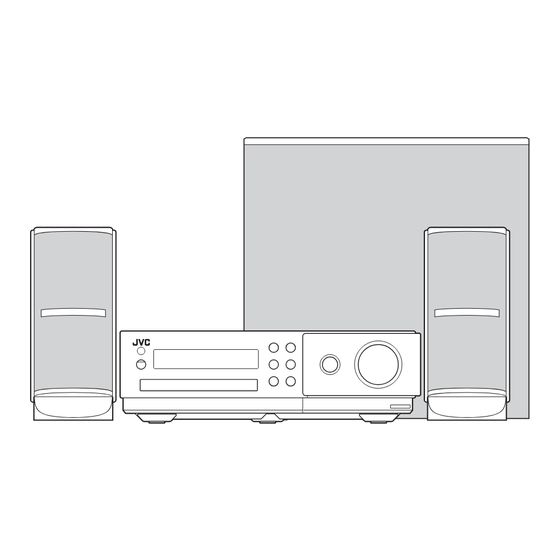
COMPACT COMPONENT SYSTEM
4 S ERVICE MANUAL
2009
MB695<Rev.001>
NX-F30B, NX-F30E, NX-F30EN,
NX-F40B, NX-F40E, NX-F40EN
COPYRIGHT © 2009 Victor Company of Japan, Limited
Lead free solder used in the board (material : Sn-Ag-Cu, melting point : 219 Centigrade)
Lead free solder used in the board (material : Sn-Cu, melting point : 230 Centigrade)
1
PRECAUTION. . . . . . . . . . . . . . . . . . . . . . . . . . . . . . . . . . . . . . . . . . . . . . . . . . . . . . . . . . . . . . . . . . . . . . . . . 1-3
2
SPECIFIC SERVICE INSTRUCTIONS . . . . . . . . . . . . . . . . . . . . . . . . . . . . . . . . . . . . . . . . . . . . . . . . . . . . . . 1-6
3
DISASSEMBLY . . . . . . . . . . . . . . . . . . . . . . . . . . . . . . . . . . . . . . . . . . . . . . . . . . . . . . . . . . . . . . . . . . . . . . . 1-6
4
ADJUSTMENT . . . . . . . . . . . . . . . . . . . . . . . . . . . . . . . . . . . . . . . . . . . . . . . . . . . . . . . . . . . . . . . . . . . . . . . 1-14
5
TROUBLESHOOTING . . . . . . . . . . . . . . . . . . . . . . . . . . . . . . . . . . . . . . . . . . . . . . . . . . . . . . . . . . . . . . . . . 1-15
SP-NXF40F
SP-NXF30F
TABLE OF CONTENTS
COPYRIGHT © 2009 Victor Company of Japan, Limited
SP-NXF30W
CA-NXF40
CA-NXF30
SP-NXF40F
SP-NXF30F
No.MB695<Rev.001>
2009/4
Advertisement

Related Manuals for JVC NX-F30B


Summary of Contents for JVC NX-F30B
-
Page 1: Table Of Contents
SERVICE MANUAL COMPACT COMPONENT SYSTEM MB695<Rev.001> 2009 4 S ERVICE MANUAL NX-F30B, NX-F30E, NX-F30EN, NX-F40B, NX-F40E, NX-F40EN SP-NXF30W SP-NXF40F CA-NXF40 SP-NXF40F SP-NXF30F CA-NXF30 SP-NXF30F COPYRIGHT © 2009 Victor Company of Japan, Limited Lead free solder used in the board (material : Sn-Ag-Cu, melting point : 219 Centigrade) - Page 2 SPECIFICATION Main unit (CA-NXF40/CA-NXF30) Tuner FM frequency 87.50 MHz - 108.00 MHz Terminal (front of the main unit) USB digital input terminal × 1 Audio output headphone terminal × 1 16 Ω - 1 kΩ Impedance Terminal (rear of the main unit) Audio output speaker terminals ×...
-
Page 3: Precaution
SECTION 1 PRECAUTION Safety Precautions (1) This design of this product contains special hardware and voltmeter. many circuits and components specially for safety purpos- Move the resistor connection to each exposed metal es. For continued protection, no changes should be made part, particularly any exposed metal part having a return to the original design unless authorized in writing by the path to the chassis, and measure the AC voltage across... - Page 4 Preventing static electricity Electrostatic discharge (ESD), which occurs when static electricity stored in the body, fabric, etc. is discharged, can destroy the laser diode in the traverse unit (optical pickup). Take care to prevent this when performing repairs. 1.5.1 Grounding to prevent damage by static electricity Static electricity in the work area can destroy the optical pickup (laser diode) in devices such as laser products.
- Page 5 Important for laser products 1.CLASS 1 LASER PRODUCT 5.CAUTION : If safety switches malfunction, the laser is able to function. 2.CAUTION : (For U.S.A.) Visible and/or invisible class II laser radiation 6.CAUTION : Use of controls, adjustments or performance of when open.
-
Page 6: Specific Service Instructions
SECTION 2 SPECIFIC SERVICE INSTRUCTIONS This service manual does not describe SPECIFIC SERVICE INSTRUCTIONS. SECTION 3 DISASSEMBLY Main body (Used figure are NX-F30E) hook 3.1.1 Removing the Top cover (See Fig.1 to 3) (1) Remove the six screws A attaching the Top and Right cov- er. - Page 7 (4) Disengage one hook a engaged bottom side of the Front (4) Remove the nine screws E attaching the Top chassis. (see panel. (See Fig.4) Fig.9) (5) Disengage two hooks b engaged both side of the Front panel. (See Fig.6) Fig.9 (5) Remove the four screws F attaching the both side of the hook...
- Page 8 3.1.5 Removing the Main board (See Fig.12, 13) 3.1.6 Removing the Rear panel (See Fig.14) (1) Disconnect the connector wire from FAN connected to con- (1) Remove the four screws K and one screw L attaching the nector CN461 of the Main board. (See Fig.12) Rear panel.
- Page 9 3.1.9 Removing the Front jack board (See Fig.17) (1) Remove the three screws Q attaching the Front jack board. Fig.17 3.1.10 Removing the Front board (See Fig.18) (1) Remove the six screws R attaching the Front board. Fig.18 (No.MB695<Rev.001>)1-9...
- Page 10 DVD mechanism assembly (3) Remove the four screws C attaching the CB holder and take out it. (See Fig.3) 3.2.1 Removing the traverse mechanism (See Fig.1 to 6) (1) Remove the two screws A attaching the tramecha holder DVD module board from top side of DVD mechanism assembly.
- Page 11 (5) Solder the solder part of DVD pick up. (See Fig.5) Solder short land section Fig.5 (6) Disconnect the card wire from CN101 CN201 on the Spring holder DVD module board. (See Fig. 6) Caution: Fig.8 • Solder the short land section on the DVD pickup be- (3) Remove the read screw from traverse mechanism assem- fore disconnecting the card wire from the connector on bly.
- Page 12 (5) Take out the pickup assembly from traverse mechanism 3.2.4 Removing the spindle motor assembly (See Fig.13) chassis by order. (See Fig.11) (1) Remove the three screws H attaching the spindle motor from spindle motor board. order 2 order 3 order 1 Spindle motor Fig.13...
- Page 13 3.2.5 Removing the tray assembly (See Fig.14 & 15) (3) Remove the two screws L attaching the shaft guide from (1) Remove the two screws J attaching the clamper base. top side. (See Fig.15) (See Fig.14) Caution: (2) Remove the one screw K attaching the shaft guide from When attach the tray assembly, boss of loading sub as- bottom side.
-
Page 14: Adjustment
SECTION 4 ADJUSTMENT ATTENTION IN SERVICE OF DVD SECTION (1) When pickup, Flash ROM, DVD module board was changed, initialize EEPROM by all means (2) When full initialization was executed, execute learning with a DVD test disc by all means. Test disc: VT-501, VT-502 Learning method: It is adjusted automatically by normal playback of a DVD disc. -
Page 15: Troubleshooting
* Indication of ShutDown cause : AA:BB:CC Shut Down Factor, AA : 0x00 = Reset Safety kind, BB : 0xA4 = PWR_THERMO Safety Detection level : 0 = LOW 0x02 = Remote control POWER key 0xA5 = AMP_THERMO 1 = HIGH 0x03 = Front Panel POWER key 0x77 = AMP_PRT 0x05 = SLEEP trigger... - Page 16 Victor Company of Japan, Limited Audio/Video Systems Division 10-1,1chome,Ohwatari-machi,Maebashi-city,371-8543,Japan (No.MB695<Rev.001>) Printed in Japan...
Need help?
Do you have a question about the NX-F30B and is the answer not in the manual?
Questions and answers