Advertisement
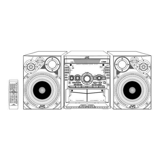
SERVICE MANUAL
COMPACT COMPONENT SYSTEM
3
2004
MB207
FM MODE
VIDEO INTRO
ON SCREEN
PREV.
SET
ENTER
PBC
STILL
KEY CONTROL
DISC
1
DISC
2
DISC
REPEAT PROGRAM RANDOM
SOUND
TAPE-A
REC
TURBO
START/STOP
SOUND
MODE
KARAOKE
MPX
ACTIVE
FADE
BASS EX.
ECHO
MUTING
REMOTE CONTROL
COMPACT
DIGITAL VIDEO
1
PRECAUTION. . . . . . . . . . . . . . . . . . . . . . . . . . . . . . . . . . . . . . . . . . . . . . . . . . . . . . . . . . . . . . . . . . . . . . . . . 1-3
2
SPECIFIC SERVICE INSTRUCTIONS . . . . . . . . . . . . . . . . . . . . . . . . . . . . . . . . . . . . . . . . . . . . . . . . . . . . . . 1-5
3
DISASSEMBLY . . . . . . . . . . . . . . . . . . . . . . . . . . . . . . . . . . . . . . . . . . . . . . . . . . . . . . . . . . . . . . . . . . . . . . . 1-6
4
ADJUSTMENT . . . . . . . . . . . . . . . . . . . . . . . . . . . . . . . . . . . . . . . . . . . . . . . . . . . . . . . . . . . . . . . . . . . . . . . 1-30
5
TROUBLESHOOTING . . . . . . . . . . . . . . . . . . . . . . . . . . . . . . . . . . . . . . . . . . . . . . . . . . . . . . . . . . . . . . . . . 1-34
MX-SK1
STANDBY/ON
SLEEP
AUX
FM/AM
HIGHLIGHT
NEXT
RETURN
3
DISC
PROGRAM
CANCEL
TAPE-B
VOLUME
SP-MXSK1
COMPACT
DIGITAL AUDIO
TABLE OF CONTENTS
COPYRIGHT © 2004 VICTOR COMPANY OF JAPAN, LIMITED
M X - S K 3
COMPACT
DIGITAL VIDEO
DISC
SELECT
ACTIVE
BASS EX.
PHONES
SELECT
EJECT
EJECT
SP-MXSK1
CA-MXSK1
EE --------- Russian Federation
Area suffix
No.MB207
2004/4
Advertisement

Related Manuals for JVC MX-SK1


Summary of Contents for JVC MX-SK1
-
Page 1: Table Of Contents
SERVICE MANUAL COMPACT COMPONENT SYSTEM MB207 2004 MX-SK1 M X - S K 3 COMPACT DIGITAL VIDEO DISC SELECT ACTIVE BASS EX. PHONES STANDBY/ON SLEEP SELECT FM MODE FM/AM VIDEO INTRO ON SCREEN HIGHLIGHT PREV. NEXT RETURN ENTER STILL KEY CONTROL... - Page 2 SPECIFICATION Amplifier section Output Power MAIN SPEAKERS 64 W per channel min. RMS both channels driven into 6 Ω at 1 kHz with no more than 0.9% total harmonic distortion. Audio input sensitivity/Impedance 400 mV/50 kΩ (Measured at 1 kHz with tape record- 3 mV/10 kΩ...
-
Page 3: Precaution
SECTION 1 PRECAUTION Safety Precautions (1) This design of this product contains special hardware and voltmeter. many circuits and components specially for safety purpos- Move the resistor connection to each exposed metal es. For continued protection, no changes should be made part, particularly any exposed metal part having a return to the original design unless authorized in writing by the path to the chassis, and measure the AC voltage across... - Page 4 Preventing static electricity Electrostatic discharge (ESD), which occurs when static electricity stored in the body, fabric, etc. is discharged, can destroy the laser diode in the traverse unit (optical pickup). Take care to prevent this when performing repairs. 1.5.1 Grounding to prevent damage by static electricity Static electricity in the work area can destroy the optical pickup (laser diode) in devices such as CD players.
-
Page 5: Specific Service Instructions
SECTION 2 SPECIFIC SERVICE INSTRUCTIONS This service manual does not describe SPECIFIC SERVICE INSTRUCTIONS. (No.MB207)1-5... -
Page 6: Disassembly
SECTION 3 DISASSEMBLY Main body 3.1.1 Removing the metal cover (See Fig.1~3) (1) Remove the six screws A on the back of the main body. (2) Remove the four screws B on each side of the body. (3) Remove the metal cover from the body by lifting the rear part of the cover. - Page 7 3.1.2 Removing the CD fitting (See Fig.4~6) • Prior to performing the following procedure, remove the metal CD tray cover. ATTENTION : Be sure to remove the CD tray fitting before removing the CD changer unit. (1) Press the STANDBY button. Press the OPEN/CLOSE but- ton to eject the CD trey.
- Page 8 3.1.3 Removing the CD fitting (See Fig.5~7) • How to eject the CD trey without turning on power. (1) Turn the loading pulley gear marked b from the back of the CD changer unit as shown in Fig.7 and draw the CD tray toward the front.
- Page 9 3.1.5 Removing the CD board (See Fig.11~13) • Prior to performing the following procedure, remove the metal CD changer unit cover and the CD changer unit. CD board Caution : Before disconnecting the card wire extending from the CD pickup, make sure to solder the short-circuit point on the CD pickup(Fig.12 and 13).
- Page 10 3.1.6 Removing the front panel assembly (See Fig.14~16) • Prior to performing the following procedure, remove the metal Front panel assembly cover and the CD changer unit. (1) Disconnect the card wire from the connector CN315, Main board CN316 CN316 CN870 on the main board.
- Page 11 3.1.7 Removing the tuner pack assembly (See Fig.17~18) • Prior to performing the following procedure, remove the metal cover and the CD changer unit. (1) Disconnect the card wire from the connector on the Rear panel tuner pack assembly on the right side of the body. (2) Remove the two screws H on the rear panel on the back of the body.
- Page 12 3.1.8 Removing the AUX & surround board (See Fig.19, 20) • Prior to performing the following procedure, remove the metal cover and the CD changer unit. (1) Disconnect the card wire from the connector CN411, Rear panel CN711 on the on the AUX & surround board on the right side of the body.
- Page 13 3.1.9 Removing the rear panel (See Fig.21~25) • Prior to performing the following procedure, remove the metal cover and the CD changer unit. Rear panel (1) Disconnect the wire from the connector on the tuner pack assembly on the right side of the body. (2) Disconnect the wire from the connector CN411, CN711 the AUX surround board.
- Page 14 3.1.10 Removing the main board / speaker board (See Fig. 26~29) • Prior to performing the following procedure, remove the metal Main board Heat sink cover and the CD changer unit, the rear panel. (1) Disconnect the card wire from the connector CN315, CN316 and CN870 on the main board.
- Page 15 3.1.11 Removing the power transformer assembly (See Fig.30~32) • Prior to performing the following procedure, remove the metal CN214 cover, and the CD changer unit, the rear panel, the speaker board. Power transfomer board (1) Disconnect the wire from connector CN21 on the power transformer board.
- Page 16 Front panel assembly • Prior to performing the following procedure, remove the metal cover, the CD changer unit and the front panel assembly. 3.2.1 Removing cassette mechanism assembly (See Fig.33,34) (1) Remove the eight screws D' attaching the cassette mech- Front panel assembly anism assembly.
- Page 17 3.2.3 Removing the switch board (See Fig.35,36) • Prior to performing the following procedure, remove the LCD Front panel assembly board. (1) Pull out the MIC level knob from the front of the front panel assembly. (2) Remove the two screws D' attaching the two wires on the bottom of the front panel assembly.
- Page 18 3.2.4 Removing the volume board (See Fig.37,38) • Prior to performing the following procedure, remove the LCD Front panel assembly board and the switch board. (1) Pull out the volume knob from the front of the front panel assembly. (2) Remove the nut from the front panel assembly. (3) Release the volume board from the tab and remove.
- Page 19 CD changer unit • Prior to performing the following procedure, remove the CD changer unit. 3.3.1 Removing the CD tray (See Fig.39~45) (1) Turn the loading pulley gear on the under side of the CD CD Tray changer unit in the direction of the arrow and draw the CD tray toward the front until it stops.
- Page 20 CD tray Connector Tray motor Sensor board Fig.44 CD tray Fig.43 Spacer Fig.45 1-20 (No.MB207)
- Page 21 3.3.2 Removing the sensor board / tray motor (See Fig.44~47) • Prior to performing the following procedure, remove the CD Turn table tray. (1) Release the two tabs attaching the sensor board on the un- der side of the DC tray. (2) Disconnect the wire from connector on the sensor board.
- Page 22 3.3.3 Removing the belt / motor board / switch board (See Fig. 48~50) • Prior to performing the following procedure, remove the CD tray. (1) Detach the belt from the pulley on the upper side of the CD changer unit (Do not stain the belt with grease). (2) Release the three tabs q and the three tabs r upward on the backside of the CD changer unit.
- Page 23 3.3.4 Removing the CD mechanism holder assembly (mechanism included) (See Fig.51~53) (1) On the bottom of the CD changer unit, turn the loading pul- ley gear in the direction of the arrow and move the CD mechanism holder assembly as shown in Fig. 52. (2) Pull outward the two stoppers setting the shafts on both sides of the CD mechanism holder assembly, and remove the CD mechanism holder assembly in the direction of the...
- Page 24 3.3.5 Remove the CD mechanism assembly (See Fig.54,55) • Prior to performing the following procedure, remove the CD mechanism holder assembly. CD mechanism (1) Remove the four screws G' attaching the CD mechanism assembly. (2) Remove the four insulators. Caution: When reassembling, attach the insulator to the correct posi- tion.
- Page 25 Cassette mechanism assembly 3.4.1 Removing the R/P & E head (See Fig. 1 to Fig. 3) (1) While shifting the trigger arms seen on the right side of the Cassette mechanism head mount in the arrow direction, turn the flywheel ( R ) in counterclockwise direction until the head mount has gone out with a click (See Fig.
- Page 26 3.4.2 Reassembling the playback / recording & eraser head (See Fig. 4 to Fig. 6) (1) Keep the direction lever of head mount assembly to left side (head direction is forward direction). (2) Fix the head mount assembly boss O', P', Q', U' and V' to mechanism sub assembly hole P, V and ditch O, U and Q (See Fig.
- Page 27 3.4.3 Removing the head amplifier & mechanism control board (See Fig. 7) (1) Remove the cassette mechanism assembly Head amp. & mechanism (2) After turning over the cassette mechanism assembly, control board remove the three screws 1 retaining the head amplifier & mechanism control board.
- Page 28 3.4.5 Removing the capstan motor (See Fig. 11) (1) Remove the two screws 3 from the capstan motor, and then remove the joint bracket. Capstan motor Joint bracket Fig.11 3.4.6 Removing the flywheel (See Fig. 12, Fig. 13) (1) Remove the head amplifier & mechanism control board. (2) Remove the capstan motor assembly.
- Page 29 3.4.8 Reassembling the control cam (See Fig. 15 to Fig. 17) (1) Shift to left side (forward direction) the head mount assembly, hole K’ of control cam into the hollow K of the mechanism sub assembly. Control cam (hole) Fig.15 Mechanism sub assembly (top side) Fig.16...
-
Page 30: Adjustment
SECTION 4 ADJUSTMENT Measurement instruments required for adjustment (1) Low frequency oscillator, Radio input signal This oscillator should have a capacity to output 0dBs to AM modulation frequency : 400Hz 600ohm at an oscillation frequency of 50Hz-20kHz. Modulation factor : 30% (2) Attenuator impedance : 600ohm FM modulation frequency : 400Hz (3) Electronic voltmeter... - Page 31 Arrangement of adjusting positions Cassette mechanism section (Mechanism A section) Cassette mechanism section (Back side) Head azimuth Head azimuth adjusting screw adjusting screw (Reverse side) (Forward side) Head azimuth Head azimuth adjusting screw Playback, recording and eraser adjusting screw Playback (Forward side) heads or playback head (Reverse side)
- Page 32 Tape recorder section Measurement Standard Adjusting Items Measurement method values positions conditions Adjust the head Maximum Confirmation Test tape 1.Playback the test tape VT710 (10kHz). azimuth screw of head angle :VT710 (10kHz) 2.With the playback mechanism or recording & output only when the Measurement playback mechanism, adjust the head azimuth...
- Page 33 Electrical performance Standard Adjusting Measurement Items Measurement method values positions conditions Adjustment of 1.With the recording and playback mechanism, AC-225 *Mode : Forward or recording bias load the test tapes(AC-225 to TYP ),and set the :4.20 A reverse mode :VR101 current mechanism to the recording and *Recording mode...
-
Page 34: Troubleshooting
SECTION 5 TROUBLESHOOTING This service manual does not describe TROUBLESHOOTING. 1-34 (No.MB207) - Page 35 (No.MB207)1-35...
- Page 36 VICTOR COMPANY OF JAPAN, LIMITED AV & MULTIMEDIA COMPANY AUDIO/VIDEO SYSTEMS CATEGORY 10-1,1chome,Ohwatari-machi,Maebashi-city,371-8543,Japan (No.MB207) Printed in Japan...