Dynon Avionics EFIS-D100 User Manual
Electronic flight information system
Hide thumbs
Also See for EFIS-D100:
- Installation manual (104 pages) ,
- Pilot's user manual (64 pages) ,
- Installation manual (45 pages)

Related Manuals for Dynon Avionics EFIS-D100


Summary of Contents for Dynon Avionics EFIS-D100
- Page 1 EFI S-D100 Electronic Flight I nformation System Pilot’s User Guide P/N 100477-000, Revision H For use with firmware version 5.4 August, 2010 Dynon Avionics This product is not approved for installation in type certificated aircraft...
-
Page 2: Copyright
Contact I nformation Dynon Avionics, Inc. 19825 141 Place NE Woodinville, WA 98072 Phone: (425) 402-0433 - 7:00 AM – 5:00 PM (Pacific Time) Monday - Friday Fax: (425) 984-1751 Dynon Avionics offers online sales, extensive support, and continually-updated information on its products via its Internet sites: ... -
Page 3: Limited Warranty
Units that have been found to have been taken apart may not be eligible for repair under warranty. Additionally, once a Dynon Avionics unit is opened up, it will require calibration and verification at our Woodinville, WA offices before it can be considered airworthy. EFIS-D100 Pilot’s User Guide... -
Page 4: Table Of Contents
OEM Installations................................1-1 Warning .....................................1-2 About this Guide................................1-2 Product Overview EFIS-D100 Hardware ................................2-1 ADAHRS Operation................................2-3 Product Operation Front Panel Layout ................................3-1 Display....................................3-2 Menus ....................................3-6 Available Pages EFIS Main pages ................................4-2 HSI Page....................................4-9 Times Page ..................................4-10 Lists Pages ..................................4-11 EFIS-D100 Pilot’s User Guide... - Page 5 HSI Display Basics ................................6-2 Navigation Radio Overlay ..............................6-4 GPS Overlay ..................................6-7 HSI Menu Structure................................6-9 Autopilot Operation Introduction and Resources .............................. 7-1 EFIS AP Indicators ................................7-2 AP Modes ..................................7-5 AP Control Methods ................................. 7-9 EFIS-D100 Pilot’s User Guide...
- Page 6 Disengage/Control Wheel Steering (CWS) Pushbutton ....................7-15 Optional Preflight Checklist ............................7-17 Alerts Alarm Indicators ................................8-1 Multiple Alarms.................................8-3 DSAB Alerts..................................8-3 Appendix Appendix A: Serial Data Output............................9-1 Appendix B: PC Support Program ............................9-3 Appendix C: Troubleshooting ............................9-3 Appendix D: EFIS-D100 Specifications..........................9-8 EFIS-D100 Pilot’s User Guide...
-
Page 7: Introduction
OEM I nstallations If your EFIS-D100 is installed by an OEM distributor, you may find that you are unable to access some menus and settings. Some Dynon distributors customize various areas of the EFIS-D100 firmware to maintain a consistent pilot experience and minimize integration issues across a large number of installations. -
Page 8: Warning
About this Guide This guide serves two purposes. The first is to help you configure and get acquainted with the EFIS-D100‘s many functions. The second is to give you quick access to vital information. For detailed technical and installation information, please refer to the EFIS-D100 Installation Guide. - Page 9 Any text following this icon describes functionality that is possible when multiple Dynon Avionics products are networked together via the Dynon Smart Avionics Bus (DSAB). Any text following this icon refers to a setting or situation which merits particularly close attention. EFIS-D100 Pilot’s User Guide...
-
Page 10: Product Overview
2. PRODUCT OVERVI EW This section provides a general overview of the various parts of the EFIS-D100 as well as a theory of operation. The information in this section serves as a reference only and helps familiarize you with the inner workings of the unit. It should not be used for diagnostic or reparative work. - Page 11 For more information on DSAB-specific alerts, refer to the DSAB Alerts section on page 8-3. OUTPUTS The EFIS-D100 has an output to drive an external customer-supplied audible device for AOA (if installed) and altitude alerts. A serial output is also provided for serial altitude encoder data. An optional Serial-to-Gray Code Converter is available for connection to Mode C Gray Code transponders.
-
Page 12: Adahrs Operation
GPS horizontal navigation, altitude hold), and allow you to engage and disengage the Autopilot. When an HS34 is configured to control the EFIS-D100, its VALUE knob changes values when in various EFIS menus. When no menus are displayed the HS34 can adjust the barometer or altitude bug. The HS34’s HEADING and COURSE knobs affect their respective parameters on the HSI page. - Page 13 GPS source acts as a substitute. When in this mode the instrument continues to provide accurate attitude. *If a GPS is present upon the loss of airspeed, the EFIS-D100 uses the GPS ground speed in its attitude calculation. When in this mode, a magenta GPS ASSIST message is displayed over the horizon and the ground speed is displayed below the IAS indicator (as shown at right).
- Page 14 COMPASS ACCURACY AND AUTOPILOT PERFORMANCE If you are using your EFIS-D100 to control Dynon’s Autopilot, it is critical that the magnetic heading be as accurate as possible for comfortable operation in HDG mode and radio-based VOR/NAV mode. The aircraft’s compass must be installed correctly, calibrated, and operating well in all attitudes.
-
Page 15: Product Operation
3. PRODUCT OPERATI ON After reading this section, you will be familiar with the basics of how to use your EFIS-D100. For details regarding specific procedures (e.g., adjusting display brightness, changing the altimeter setting, setting the clock, etc.) please refer to the EFIS Operation section. - Page 16 Product Operation Display The EFIS-D100 display is the most obvious and commonly used output of the device. It is capable of displaying EFIS, HSI, and/or engine data simultaneously. SCREENS AND PAGES The terms in the following bulleted list are used in this section and are defined as follows: ...
-
Page 17: Display
The SCREEN LIST Menu uses icons to illustrate the layout for each screen configuration. EFIS/EMS EFIS/AUX EFIS/FUEL EFIS/TIMES EFIS/HSI (in default screen rotation) EMS/EFIS EMS/AUX EMS/TIMES EMS/FUEL EMS/HSI EFIS (default EFIS-D100 boot-up screen; in default rotation) EFIS/EMS EMS/EFIS HSI/EMS EFIS-D100 Pilot’s User Guide... - Page 18 If you configurations. wish to access screens that are not in your rotation, use the SCREEN LIST as described above. EFIS-D100 Pilot’s User Guide...
- Page 19 Press SETUP, then press ORDER to display the menu used to change the screen order. Scroll through the pre-defined screens using the DOWN▼/UP▲ buttons. Press the MV DN▼ EFIS-D100 Pilot’s User Guide...
-
Page 20: Menus
Likewise, press the MV UP▲ button to move the selected screen up in the screen list. Menus All interaction with the EFIS-D100 is accomplished through the use of its menu system. The menu system is accessed and navigated via the six buttons located on the front of the unit. - Page 21 MENU►. Pressing the button switches the menu to display the right page’s menu, and the label switches to read ◄MENU. The arrow on this button always points to the side of the screen whose menu is displayed when pressing the button. EFIS-D100 Pilot’s User Guide...
- Page 22 “EFIS > INFO > LEFT” indicates entering the EFIS menu, pressing MORE, then pressing INFO, and then pressing LEFT to enter the left info item menu. Note that the MORE button is not included in the sequence, since pressing MORE reveals more options in the same level of the menu system. EFIS-D100 Pilot’s User Guide...
-
Page 23: Available Pages
Note: EMS-based pages use data that is obtained from Dynon’s EMS products. You may only display these pages on your EFIS-D100 if you own a Dynon EMS-based product, and the two units are connected via DSAB. Refer to the EFIS-D100 Installation Manual for details regarding proper connection between Dynon products and other devices in your system. -
Page 24: Efi S Main Pages
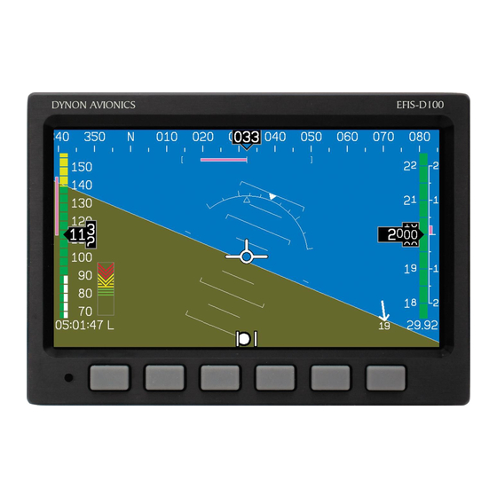
Available Pages EFI S Main pages Available in 1/3, 2/3 and full formats The EFIS-D100 default screen rotation includes only 2/3 EFIS pages combined with the various EMS and HSI pages described below. However, you may also choose screen configurations that use 1/3 and full-screen pages. - Page 25 Unlike a mechanical artificial horizon, the EFIS-D100’s horizon has no roll or pitch limitation. The horizon line stays parallel to the Earth’s horizon line regardless of attitude. The parallel lines above and below the horizon line are the pitch indicator lines, with each line indicating 5 degrees of pitch.
- Page 26 Like a conventional gyro-stabilized magnetic compass, magnetic heading reacts immediately to turn rate so that heading changes are reflected immediately. It then uses magnetometer data over the long term to ensure that it remains correct. Additionally, heading is corrected for attitude so that it is accurate as you pitch and roll. EFIS-D100 Pilot’s User Guide...
- Page 27 4000 ft/min, the VSI bar is scaled to indicate a 6-second trend only up to 1000 ft/min. When set to display 1000 ft/min, the VSI bar is scaled to indicate a 12-second trend up to 500 ft/min. EFIS-D100 Pilot’s User Guide...
- Page 28 Located in the lower right corner of the EFIS page, the elevator trim indicator displays the relative trim of the elevator in graphic form. The elevator trim indicator can only be displayed on the EFIS-D100 if an elevator trim sensor is properly connected to one of the 3 EMS GP inputs (on a DSAB-connected EMS device), and is properly configured in the EMS setup.
- Page 29 AOA changes with configuration. Because of this, a stall could occur anywhere inside the yellow range, but will occur at the same point every time given a specific configuration. Refer to the EFIS-D100 Installation Guide for more information on calibrating the AOA indicator.
- Page 30 Local time (L), Zulu time (Z), or a timer (T). If a GPS is connected to your Dynon network and is outputting time information, the Zulu time of all connected products is auto-set to that reported by the GPS. EFIS-D100 Pilot’s User Guide...
-
Page 31: Hsi Page
HSI Page Available in 1/3 format Your EFIS-D100 can function as a Horizontal Situation Indicator (HSI) when it is receiving data from Dynon’s HS34 (connected to a NAV radio), an external GPS, or Garmin SL30 Nav radio. The HSI information is overlaid on a directional gyro (DG) representation of the EFIS's stabilized magnetic heading information. -
Page 32: Times Page
The ENGINE TIMERS section is native to the EMS and will not appear on the EFIS-D100 unless a Dynon EMS product is properly connected and running. The tach timer keeps track of engine time (normalized to the user- configured cruise RPM). -
Page 33: Lists Pages
14 lines of text and 40 characters per line. Checklists/data panels must be defined and uploaded to the EFIS-D100 as described by the Dynon Product Support Program, available at downloads.dynonavionics.com. Reference the help file that accompanies this software for more information. -
Page 34: Efis Operation
POWER – Pow er on/ off When the EFIS-D100 is turned off but still has a power source via one of the three power inputs, press the far left button to turn the unit on. Likewise, once the unit is on and no menus are displayed, push and hold the leftmost button to turn it off. -
Page 35: Bugs - Setting Bug Markers
TRK depending on the autopilot’s mode of operation. Press the TOGGLE button to turn on or off the heading or track bug display on the horizontal heading tape. Note that this affects the display of the heading bug on the HSI page as well. EFIS-D100 Pilot’s User Guide... - Page 36 DEC- and INC+ to change the selected digit. Press the SYNC button to synchronize the airspeed bug to your current indicated a irspeed. If you have the airspeed bug displayed, the marker moves up or down the airspeed tape as you change its value. EFIS-D100 Pilot’s User Guide...
- Page 37 500 feet from the target altitude. The target altitude is considered captured when altitude is withi 150 feet of the target. Flying more than 200 feet away from the target triggers a short audio alert and alternates the bug in EFIS-D100 Pilot’s User Guide...
-
Page 38: Lists - Using Checklists And Data Panels
The Dynon Support Program allows you to enter your own checklists or select from included data panels. These checklists and data panels can then be uploaded to your EFIS-D100 for quick access from the main menu or from your screen rotation. Data panels and checklists can be included beneath 5 user-configurable categories and each category can contain up to 5 checklists or data panels. - Page 39 2/3 of the screen displays the checklist while the left side displays a 1/3 format EFIS page. See the Dynon Support Program for more detailed information on entering checklists and data panels. It can be downloaded from our website at downloads.dynonavionics.com. EFIS-D100 Pilot’s User Guide...
-
Page 40: Setup - Setting Preferences
Zulu times independently. Once you have set Zulu time, you should never need to change it, as it is independent of daylight saving time. When connected to a GPS which is outputting time information, Zulu time is synchronized to the GPS and cannot be set on the EFIS-D100. EFIS-D100 Pilot’s User Guide... - Page 41 SEL► moves the highlight to the next set of digits. The order of selection is 1. Local hours, 2. Local minutes (adjustable only as ½-hour offsets from Zulu minutes), 3. Zulu hours, 4. Zulu minutes. When connected to a GPS, you are not permitted to adjust the Zulu time on the EFIS-D100 ...
- Page 42 EFIS presentation. When set to “2”, the r scale moves with the horizon, while the pointer stays fixed on the screen, like most mechanical attitude instrument presentations. EFIS-D100 Pilot’s User Guide...
- Page 43 Toggles the display of the ground track indicator on the heading tape. The track indicator is a magenta arrow and is only displayed when the EFIS-D100 is receiv valid GPS data from an external source. If the GTRK button status displays “Y” and no ground track arrow is displayed, the EFIS-D100 cannot detect your GPS, or the GPS does not yet have a satellite lock.
-
Page 44: Info - Informational Items
Toggles the display of a “V”-shaped course pointer on the heading tape. Li ke the CDI, this can only be displayed when the EFIS-D100 is receiving a valid co urse from the NAV source selected on the HSI page. If the CRS button status di splays “Y”... - Page 45 The top row, labeled MX, is the maximum positive g-force experienced by the EFIS-D100 since reset. The middle row, labeled CR, is the current g-force experienced by the EFIS-D100. The bottom row, labeled MN, is the minimum g-force experienced by the EFIS- 0 since reset.
-
Page 46: Dim - Changing Screen Brightness
In the EFIS > DIM menu, press BRITR or DRKR to change the brightness of the display. It is not possible to turn the screen completely black. Note that if power to the EFIS-D100 is cycled, the screen is reset to full brightness. -
Page 47: Timer - Setting And Using A Timer
The UP/DN button toggles the menu and timer between an up timer and a down timer. When switching to an up timer, the timer set value resets, allowing the up timer to count up from 0:0 0:00. To reset the timer, press the UP/DN button twice. 5-14 EFIS-D100 Pilot’s User Guide... -
Page 48: Oatset - Setting Temperature Offset
DATLOG – Logging and retrieving data The EFIS-D100 provides two options for logging data. You may configure the EFIS-D100 to log data to its internal memory for later retrieval or you may record streaming data serial output to an external device (such as a laptop computer) in real-time from the EFIS serial port (as documented on page 9-2). - Page 49 2 hours of cumulative data can be recorded; with a 10-second interval, at least 20 hours; with a 30-second interval, at least 60 hours, and with a 60-second interval, at least 120 hours. When the EFIS-D100 internal storage fills up, new records overwrite the oldest records.
-
Page 50: Hsi Operation
30 Nav/Comm radio via a serial connection (Nav data), a Garmin GNS-430/530 GPS/Nav/Comm (GPS data), or any GPS that outputs in either NMEA-0183 or aviation format. Please refer to the EFIS-D100 Installation Guide for instructions on how to connect these devices to your Dynon network. Also, ensure your GPS device is configured to output magnetic heading since all calculations and displays are done in reference to the local magnetic heading. -
Page 51: Hsi Display Basics
TO/FROM flag on a mechanical CDI. Do not rely on any indications on this page except for the DG and TAS when this flag is set. "VOR" in green text. This means the radio is tuned to a standard VOR station and is giving a valid TO or FROM indication. EFIS-D100 Pilot’s User Guide... - Page 52 2. Digital heading indicator. The number in this box is the current magnetic heading of the aircraft in degrees from 001 to 360. The accuracy of this data depends on the accuracy of the h eading calibration for your EFIS-D100. 3. Directional Gyro (DG). The ring of tick marks and numbers acts as a traditional directional gyro.
-
Page 53: Navigation Radio Overlay
VOR or a localizer. If the NAV radio indicates that you are no currently tuned to an active frequency, this indicator is not displayed. The direction of thi s course is set EFIS-D100 Pilot’s User Guide... - Page 54 5. Glideslope Indicator. This appears only when tuned to an ILS. It displays deviation as 0.5 degrees when deflected full scale. This does not have an indicator on it unless the glideslope is va lid as defined by the glideslope flag. EFIS-D100 Pilot’s User Guide...
- Page 55 The HS34 adds the ability to display information from a marker beacon receiver. If you have marker beacon receiver connected and configured (as described in the EFIS-D100 Installation Guide), the “O,” “M,” and “I” indications are displayed on the HSI page. If configured, the HS34 plays the appropriate Morse Code tones on its audio output.
-
Page 56: Gps Overlay
CDI indicator found in basic aircraft, the CDI needle on an HSI rotates with the DG and course indicator. By turning the aircraft towards the CDI needle so the CDI needle is "on top" of the course line you reduce your deviat ion. EFIS-D100 Pilot’s User Guide... - Page 57 The three options are "E" for enroute (5 n.m. full scale), "T" for terminal (1 n.m. full scale), and "A" for approach (0.3 n.m. full scale). The current scale name and full scale range is indicated on the screen. EFIS-D100 Pilot’s User Guide...
-
Page 58: Hsi Menu Structure
NAV1, NAV2, etc, if you have multiple units connected. The NAV SRC button on the HS34 only works when the HSI page is displayed on the DSAB master. If it is pressed when no HSI is displayed, it has no effect. EFIS-D100 Pilot’s User Guide... - Page 59 This is true when you are in most GPS modes. CALE (GPS mode) - This is used to cycle through the three GPS scale modes. The scale button only exists if the source you are connected to is not providing scale information. 6-10 EFIS-D100 Pilot’s User Guide...
-
Page 60: Autopilot Operation
This section guides you through the indicators and operation of Dynon’s EFIS-based Autopilot (AP) system. This section assumes that the AP has already been installed, configured, and tuned according to the EFIS-D100 Installation Guide. Additionally, it assumes that you are already familiar with the operation of the EFIS-D100 menu system, documented throughout this guide. -
Page 61: Efis Ap Indicators
EFI S AP I ndicators When 1 or more servos are installed and configured, the EFIS-D100‘s EFIS presentation includes some new indicators, described below. If these indicators do not appear on the EFIS page, the AP installation procedure must be performed per the AP Installation and Configuration chapter of the EFIS-D100 Installation Guide. - Page 62 S tatus: ARINC GPS Steering Horizontal Navigation Mode GST (Magenta Text) Status: Radio-based VOR Horizontal Navigation Mode VOR (Green Text) Status: Radio-based LOC Horizontal Navigation Mode LOC ( Green Text) Status: Altitude Hold Mode; AP uses Altitude B ug as target altitude EFIS-D100 Pilot’s User Guide...
- Page 63 If an error in the Pitch servo is detected, the AP reports an error in the Pitch servo, but continues operation of the Roll servo. If, while f lying in GPS NAV mode, the user cancels the active waypoint or the GPS sends malformed navigation data, the AP fails over to TRK mode. EFIS-D100 Pilot’s User Guide...
-
Page 64: Ap Modes
EFIS > SETUP > AP > ROLL SERVO menu. The AP will not exceed the maximum bank angle, set in that menu. See the EFIS-D100 Installation Guide for detailed information on configuring these parameters. - Page 65 When the AP is engaged in GPS Navigation Mode, it takes its instruction from the GPS unit’s horizontal navigation information. The AP’s goal in the roll axis is to center the CDI, flying you to the active waypoint on the desired course. EFIS-D100 Pilot’s User Guide...
- Page 66 GPS is selected as the HSI page’s NAVSRC and is outputting ARINC roll steering commands. NAV/GPSS mode is indicated by the annunciation 'GST' i the AP LAT:LON status. Note that GPSS is always used when the GPS provides roll steering commands. EFIS-D100 Pilot’s User Guide...
- Page 67 In the example at right, the indicator appears until the pilot trims the aircraft nose up until neutral trim. During turbulence and small bumps the trim indicator may flash on and off. Do not take action based on the trim indicator until it remains on for several seconds. EFIS-D100 Pilot’s User Guide...
-
Page 68: Ap Control Methods
(NAV). When the roll axis of the AP is engaged (by pressing button 3, the lateral engage button), it flies in the mode set in this menu. Pressing this button brings up another menu where you can select the armed AP mode. As soon as you select a mode, the AP menu is immediately displayed again. EFIS-D100 Pilot’s User Guide... - Page 69 180: Puts the AP into 180 Mode TRK (or HDG, if no GPS available) and ALT modes, and sets the heading bug to 180º from the current ground track. While in 180 Mode, the 180 button is highlighted, and the AP Status Indicator displays “180” in the roll axis position. 7-10 EFIS-D100 Pilot’s User Guide...
-
Page 70: Ap74 Autopilot Control
HDG, TRK, or NAV modes upon pressing the AP button. Read Pre-select Configuration on page 7-14 for more details on configuring this behavior for your needs. If no mode is armed, pressing the AP button engages the AP in HDG mode only. EFIS-D100 Pilot’s User Guide 7-11... - Page 71 GPS ground track upon pressing the TRK button. Read Pre-select Configuration on page 7-14 for more details on configuring this behavior for your needs. The heading/track bug can always be adjusted while the AP is engaged. 7-12 EFIS-D100 Pilot’s User Guide...
- Page 72 The first push of the VALUE knob activates the FIRST ACTION mode (ALT, HDG or BARO) and displays a “pop- up” window indicating the current mode and value. Rotating the knob within 5 seconds changes the value of the EFIS-D100 Pilot’s User Guide 7-13...
- Page 73 AP74, the ALT bug is synchronized to the current altitude. When the autopilot is engaged, the bug settings are not modified. This allows you to enter a desired heading and/or altitude prior to engaging the 7-14 EFIS-D100 Pilot’s User Guide...
-
Page 74: Disengage/Control Wheel Steering (Cws) Pushbutton
If configured in the EFIS > SETUP > AP > BUTTON CONFIG menu, the button can also serve as a control wheel steering mechanism, as described below. EFIS-D100 Pilot’s User Guide 7-15... - Page 75 Last Heading and/or Altitude (LAST HDG/ALT) - the AP is engaged and returns to the selected Heading and/or Altitude Hold Heading and/or Altitude (HOLD HDG/ALT) - the AP is engaged and changes the selected Heading and/or Altitude to match the current Heading and/or Altitude. 7-16 EFIS-D100 Pilot’s User Guide...
-
Page 76: Optional Preflight Checklist
1. With the circuit breaker for the servos powered OFF, test the controls for proper operation of the control surfaces. The controls should feel normal; the servos should add little resistance. The EFIS-D100 should display an alert regarding DSAB connectivity. Additionally, the AP Status display should show AP:ERR:ERR. -
Page 77: Alerts Alarm Indicators
Note that alarms may not be acknowledged during the initial two seconds of the first alarm. In an alarm condition, the EFIS-D100 does not alert you audibly. The audio out connection on the EFIS-D100 is for AOA and autopilot alerts only. If you have a Dynon EMS-based product installed, connected to both your EFIS-D100 and cockpit audio system, EMS-based alarms will still sound an audible alarm. - Page 78 When acknowledging a voice alert from the HS34 or AP74, the full text of the current alarm is read before it is silenced; no other queued alarms will be announced after that. EFIS-D100 Pilot’s User Guide...
-
Page 79: Multiple Alarms
This error indicates that a unit that was expected to be on the DSAB network was not found. For example, if – in a system consisting of a FlightDEK-D180, EFIS-D100, and an HS34 – all three units are not present, this error appears. - Page 80 If the HS34 is not communicating on DSAB properly, both the NAV and GPS lights are illuminated. During normal system operation both lights will never be illuminated simultaneously; dual illumination indicates a communication failure. Additionally, if the DSAB network fails in flight “DSAB ERROR” will be annunciated via HS34’s the audio output. EFIS-D100 Pilot’s User Guide...
-
Page 81: Appendix
The EFIS-D100 has one RS232 serial port which outputs EFIS data. Technical information on the installation and connection to these serial ports can be found in the EFIS-D100 Installation Guide. To log EFIS data, you must connect the serial port to a PC. This serial data can be logged using any standard serial terminal program such as HyperTerminal®. - Page 82 Description Notes Char Hour 00 to 23, current Zulu time hour according to EFIS-D100’s internal clock. Minute 00 to 59, current Zulu time minute according to EFIS-D100’s internal clock. Second 00 to 59, current Zulu time second according to EFIS-D100’s internal clock.
-
Page 83: Appendix B: Pc Support Program
Appendix C: Troubleshooting See the EFIS-D100 Installation Guide Appendix for a variety of troubleshooting tips and solutions. You may also reach us and other active users at our online support forums located at: forum.dynonavionics.com. - Page 84 EFIS-D100’s firmware version number ready when you contact us. To locate your product’s firmware version, refer to the Check firmware version section on page 5-11. See the following list of alert messages displayed by the EFIS-D100. The list provides information about what they mean and what to do about them.
- Page 85 Note that this alert only appears when airspeed is non-zero; using the EFIS-D100 on the bench will not trigger this alert. TEMPERATURE When the unit is turned on after having been off...
- Page 86 EDC-D10A connected. Attempt the connection within the first few seconds of operation. Note that the EFIS-D100 does not have internal magnetic sensors and thus requires the EDC- D10A be connected. EFIS-D100 Pilot’s User Guide...
- Page 87 D100 and the EDC-D10A as well as that of the some reason. Either the EDC-D10A has become OAT sensor. disconnected, or the OAT sensor itself has become disconnected from the EDC-D10A. EFIS-D100 Pilot’s User Guide...
-
Page 88: Appendix D: Efis-D100 Specifications
Power Power: 12 watts typical; 17 watts maximum Connections Wiring: D-25 male Type: AMLCD, TFT (Thin Film Transistor) Backlight: 400 nits or 800 nits Screen Size: 7.0” diagonal (178 mm) Resolution: 854 x 480 color pixels EFIS-D100 Pilot’s User Guide... - Page 89 Appendix 1 - Audio Alarm 1 - RS-232 bidirectional PC communication Inputs/Outputs 1 - RS-232 data input (GPS, SL30, etc.) 1 - Dynon Smart Avionics Bus (DSAB) EFIS-D100 Pilot’s User Guide...
Need help?
Do you have a question about the EFIS-D100 and is the answer not in the manual?
Questions and answers