Table of Contents
Advertisement
PRINT
®
S-Series
TM
DOT - Private Use Lift
Operator Manual
08/02/05
32DSSP03.B
©1992-05 RICON CORPORATION
All Rights Reserved
U.S. Patent Nos: 4,534,450; 5,308,215; 5,445,488; 5,605,431; 5,944,473
®
Australian Patent No: 661127; 687,066
Canadian Patent No: 1,245,603; 2,168,761
Other U.S. and foreign patents pending.
Printed in the United States of America
Advertisement
Table of Contents

Related Manuals for Ricon S2003

Summary of Contents for Ricon S2003
- Page 1 ® S-Series DOT - Private Use Lift Operator Manual 08/02/05 32DSSP03.B ©1992-05 RICON CORPORATION All Rights Reserved U.S. Patent Nos: 4,534,450; 5,308,215; 5,445,488; 5,605,431; 5,944,473 ® Australian Patent No: 661127; 687,066 Canadian Patent No: 1,245,603; 2,168,761 Other U.S. and foreign patents pending.
- Page 2 This RICON product must be installed and serviced by RICON authorized dealers. The owner must refer to this manual for operating in- structions, then retain it for future reference by RICON authorized dealers that perform maintenance. “DOT – Private Use Lift” verifies that this plat- form lift meets only the private use lift require- ments of FMVSS no.
- Page 3 REVISION RECORD PAGES DESCRIPTION OF CHANGE 32DSSP03. 1-1, 2-2, Listed weight has changed to 600lbs. 5669 1-4, 2-4 Changed pendant type to universal (p/n 14727). Changed Max Load decal to 600lb (26183). END OF LIST 32DSSP03.B...
-
Page 4: Table Of Contents
TABLE OF CONTENTS Chapter: Page INTRODUCTION................... 1-1 A. PRODUCT SUPPORT ................1-1 B. PRODUCT WARRANTY ................1-2 C. SHIPMENT INFORMATION ................1-3 D. GENERAL SAFETY PRECAUTIONS ............1-3 MAJOR LIFT COMPONENTS ..............1-4 PLATFORM OPERATING VOLUME.............1-6 II. OPERATING INSTRUCTIONS..............2-1 A. SAFETY PRECAUTIONS ................2-1 B. DAILY SAFETY CHECK................2-2 C. - Page 5 This page intentionally left blank. 32DSSP03.B...
-
Page 6: Introduction
Ricon recommended cleaning, lubrication, and inspection instruc- tions given in Chapter III, “Maintenance”. A. PRODUCT SUPPORT If there are questions about this manual, or additional copies are needed, please contact Ricon Product Support at one of the following locations: Ricon Corporation 7900 Nelson Road Panorama City, Ca 91402 .................. -
Page 7: Product Warranty
Repair or replace lift power train parts for a period of five years from date of purchase. A list of parts covered can be obtained from your Ricon authorized dealer or Ricon Product Support. If you need to return a product: Return this Ricon product to the installing dealer. Please give advance notice, and allow time for repairs. -
Page 8: Shipment Information
Be sure installation kit contains all items listed on kit packing list. Please report any miss- ing items immediately to Ricon Product Support. The warranty and owner registration cards must be completed and returned to Ricon within 20 days to validate warranty. This information can also be entered in the table located on the first page of this manual. -
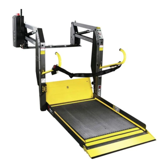
Page 9: Major Lift Components
E. MAJOR LIFT COMPONENTS The references used throughout this manual are illustrated in Figure 1-1 and defined in Table 1- 1. Refer to the Service Manual, Chapter IV, “Parts Diagrams and Lists” for more details. STOW DEPLOY DOWN LIFT WITH SPLIT-PLATFORM FIGURE 1-1: PRIVATE USE WHEELCHAIR LIFT COMPONENTS 1 - 4 32DSSP03.B... - Page 10 TABLE 1-1: S-SERIES PRIVATE USE LIFT COMPONENT TERMS NAME DESCRIPTION 1, 2, Left, right, front, Position references when installed lift is viewed from outside of vehicle. 3, 4 back Bridgeplate Senses if weight is present on the lowered bridgeplate. load sensor Hydraulic (left and right) Telescoping single-acting cylinders convert cylinder...
-
Page 11: Platform Operating Volume
UNOBSTRUCTED PLATFORM OPERATING VOLUME FIGURE 1-2: PLATFORM OPERATING VOLUME TABLE 1-2: S-SERIES OPERATING VOLUME DIMENSIONS, inches (mm’s) MODEL S1231 30 (762) 42 (1,067) 30 (762) S2003 30 (762) 51 (1,295) 30 (762) S2005 32 (813) 51 (1,295) 30 (762) S5003... -
Page 12: Operating Instructions
II. S-SERIES PRIVATE USE LIFT OPERATING INSTRUCTIONS his chapter contains safety precautions, daily safety check instructions, control and indicator descriptions, and operating instructions for the RICON S-Series Private Use wheelchair lift. This chapter must be thoroughly understood by operator before using lift. -
Page 13: Daily Safety Check
Do not load an oversize wheelchair into vehicle if it is too large to pivot freely inside vehicle. Read and understand these safety precautions. Review them periodically and ask other opera- tors to read them as well. Contact a Ricon authorized dealer or Ricon Product Support if there are questions. -
Page 14: Platform Motions
C. PLATFORM MOTIONS TABLE 2-1: PLATFORM MOTIONS MOVEMENT DESCRIPTION Platform unfolds, or deploys, out of vehicle from stowed po- sition to floor level position. If equipped with a power door DEPLOY operator, the doors automatically open before lift deploys. Platform lowers from vehicle floor level position towards ground level. -
Page 15: Controls And Indicators
D. CONTROLS AND INDICATORS WARNING THE LIFT IS ALLOWED TO OPERATE ONLY WHEN THE VEHICLE MANU- FACTURER INTERLOCK CIRCUITRY IS ACTIVATED. IF NECESSARY, REFER TO VEHICLE OPERATOR MANUAL FOR INTERLOCK INSTRUCTIONS. DO NOT ATTEMPT TO OPERATE LIFT WITH INTERLOCK BYPASSED. CONTROL PENDANT Refer to Figure 2-5. -
Page 16: Control Switch
CONTROL SWITCH Refer to Figure 2-6. An alternate lift control switch is located on the left side platform armrest. The spring-loaded switch lever can be used by the passenger to control UP and DOWN motions of the platform. To move platform downward push and hold switch lever forward, and to move platform upward pull and hold lever back. -
Page 17: Bridgeplate Load Sensor
Refer to Figure 2-7. The Control System Circuit Breaker is located on the hydraulic pump as- sembly. In case of a control system short circuit, circuit breaker button will “pop-out”. If pressing and releasing button does not reset power, do not press and hold. Contact a Ricon authorized dealer for repair. -
Page 18: Threshold Safety System
THRESHOLD SAFETY WARNING SYSTEM Refer to Figure 2-9 for the location of threshold warning system components. The lift incorpo- rates two light beams that detect when a passenger (or object, such as a wheelchair) is in the vicinity of the baseplate (threshold area). The beams are enabled when the platform is one inch, or more, below the vehicle floor. -
Page 19: Lift Cycle Counter
LIFT CYCLE COUNTER Refer to Figure 2-11. The cycle counter is located inside the hydraulic pump housing and visible through a slot on the rear side. The counter advances each time the platform moves through a complete cycle, which consists of the platform moving from the vehicle floor to the ground and back to the floor. -
Page 20: Normal Lift Operation
DO NOT EXCEED RATED LOAD CAPACITY OF 600 POUNDS (273 KGS). PRIOR TO USE, INSPECT WHEELCHAIR LIFT FOR PROPER FUNCTION, REQUIRED MAINTE- NANCE, OR DAMAGE. IF A PROBLEM EXISTS, DO NOT USE LIFT AND CONTACT A RICON AU- THORIZED DEALER FOR REPAIR. -
Page 21: Exiting Vehicle
CAUTION Be certain wheelchair is clearly within perimeter of platform and does not interfere with operation of rollstop. RAISE PLATFORM - Push and hold UP button until platform rises and stops automati- cally at floor level. Release wheelchair brakes and carefully enter vehicle. Refer to “Stowing Platform”... -
Page 22: Manual Operation
MANUAL OPERATION The lift can be operated manually if the lift is not functioning or the primary electrical power source is absent. Ricon recommends that manual operation be used only for exiting passen- gers from vehicle. Preparation: Be certain vehicle is on a level area and away from traffic. Allow space for platform movement plus space to exit from platform. - Page 23 CAUTION Do not open pump release valve more than ¼ turn. Opening valve further may cause it to disengage from pump body, which will disable manual pump. FIGURE 2-13: OPEN RELEASE VALVE Refer to Figure 2-13. Open release valve by turning it 1/4 turn counter-clockwise and platform will begin to lower.
-
Page 24: Lower Platform
2. LOWER PLATFORM CAUTION Do not open pump release valve more than ¼ turn. Opening valve further may cause it to disengage from pump body, which will disable manual pump. Refer to Figure 2-13. Turn valve 1/4 turn counter-clockwise to begin lowering plat- form. - Page 25 This page intentionally left blank. 32DSSP03.B 2 - 14...
-
Page 26: Maintenance
Additional maintenance information is available in the S-Series Private Use service manual, part number 32DSSP04. This manual is available from Ricon in printed hard copy, or at the Ricon website in PDF format. The website is located at www.riconcorp.com. At the website, click on “Technical Documents”, “I agree”, and then “Service Manuals”. - Page 27 32DSSP04 following directions on con- tainer. Remove excess grease from surrounding areas. CAUTION A Ricon authorized dealer must perform the annual safety check. ANNUAL SAFETY CHECK (or 3600 cycles of operation) Check hydraulic cylinder for evidence of leaks.
-
Page 28: Decal Part Numbers And Locations
PART OF SERIAL MANUAL OPERATION DECAL (LOCATED ON NUMBER DECAL (ONLY RICON INNER SIDE OF HYDRAULIC REPLACEABLE) CYLINDER; ONLY RICON REPLACEABLE) CORPORATION 7900 Nelson Road, Panorama City, CA 91402 mfg. date: Made in U.S.A. CORPORATION 12450 Montague St., Pacoima, CA 91331 mfg. - Page 29 This page intentionally left blank. 32DSSP03.B 3 - 4...
Need help?
Do you have a question about the S2003 and is the answer not in the manual?
Questions and answers