Basler DECS-250 Instruction Manual
Digital excitation
Hide thumbs
Also See for DECS-250:
- Instruction manual (352 pages) ,
- Instruction manual (8 pages) ,
- Instruction manual (374 pages)
Table of Contents
Advertisement
Quick Links
Download this manual
See also:
Instruction Manual
DIGITAL EXCITATION CONTROL SYSTEM
CALL US TODAY
CALL US TODAY
1-888-POWER-58
1-888-POWER-58
INSTRUCTION MANUAL
FOR
DECS-250
REQUEST A QUOTE
REQUEST A QUOTE
parts@genpowerusa.com
parts@genpowerusa.com
Publication: 9440300990
Revision: G
08/14
www.genpowerusa.com
www.genpowerusa.com
SHOP ONLINE
SHOP ONLINE
Advertisement
Table of Contents

Related Manuals for Basler DECS-250


Summary of Contents for Basler DECS-250
- Page 1 INSTRUCTION MANUAL DIGITAL EXCITATION CONTROL SYSTEM DECS-250 Publication: 9440300990 Revision: G 08/14 CALL US TODAY CALL US TODAY REQUEST A QUOTE REQUEST A QUOTE SHOP ONLINE SHOP ONLINE 1-888-POWER-58 1-888-POWER-58 parts@genpowerusa.com parts@genpowerusa.com www.genpowerusa.com www.genpowerusa.com...
- Page 2 CALL US TODAY CALL US TODAY REQUEST A QUOTE REQUEST A QUOTE SHOP ONLINE SHOP ONLINE 1-888-POWER-58 1-888-POWER-58 parts@genpowerusa.com parts@genpowerusa.com www.genpowerusa.com www.genpowerusa.com...
- Page 3 9440300990 Rev G Preface This instruction manual provides information about the installation and operation of the DECS-250 Digital Excitation Control System. To accomplish this, the following information is provided: • General Information • Human-Machine Interface • Functional Description • Installation •...
- Page 4 For a complete copy of GNU GENERAL PUBLIC LICENSE Version 2, June 1991 or GNU LESSER GENERAL PUBLIC LICENSE Version 2.1, February 1999 refer to www.gnu.org or contact Basler Electric. You, as a Basler Electric Company customer, agree to abide by the terms and conditions of GNU GENERAL PUBLIC LICENSE Version 2, June 1991 or GNU LESSER GENERAL PUBLIC LICENSE Version 2.1, February 1999, and as such hold...
-
Page 5: Table Of Contents
Frequency Protection ..........................43 Power Protection ............................. 44 Field Protection ............................47 Sync-Check Protection ..........................51 Generator Frequency Less Than 10 Hertz ....................52 Configurable Protection ........................... 52 DECS-250 Preface CALL US TODAY CALL US TODAY REQUEST A QUOTE REQUEST A QUOTE... - Page 6 ® BESTCOMSPlus Software ........................121 General Description ..........................121 Installation ............................. 122 ® Activation of the DECS-250 Plugin for BESTCOMSPlus ..............122 Menu Bars ............................. 126 Settings Explorer ........................... 128 Metering Explorer ..........................129 Settings File Management ........................129 Automatic Metering Export ........................131 Firmware Updates ..........................
- Page 7 Modbus Modes of Operation ......................... 196 Detailed Message Query and Response for RTU Transmission Mode ..........199 Data Formats ............................202 Secure DECS-250 Login via Modbus ....................204 Modbus Parameters ..........................205 PROFIBUS Communication ........................237 Data Types ............................237 Setup ..............................
- Page 8 Specifications ............................321 Installation ............................. 323 Communications ............................ 330 Functional Description ........................... 330 Metering ..............................332 Maintenance ............................332 Revision History ............................333 Preface DECS-250 CALL US TODAY CALL US TODAY REQUEST A QUOTE REQUEST A QUOTE SHOP ONLINE SHOP ONLINE 1-888-POWER-58 1-888-POWER-58 parts@genpowerusa.com...
-
Page 9: Introduction
9440300990 Rev G Introduction DECS-250 Digital Excitation Control Systems offer precise excitation control and machine protection in a compact package. DECS-250 adaptability to many applications is assured through configurable contact inputs and outputs, flexible communication capabilities, and programmable logic implemented with the ®... -
Page 10: Application
Excitation power is supplied from the DECS-250 by means of a filtered, switching power module that uses pulse-width modulation. It is capable of supplying 15 Adc continuously at a nominal voltage of 32, 63, or 125 Vdc. -
Page 11: Storage
Figure 1. DECS-250 Style Chart Storage If a DECS-250 will not be placed in service right away, store it in the original shipping carton in a moisture- and dust-free environment. The temperature of the storage environment must be within the range of –40 to 85°C (–40 to 185°F). - Page 12 9440300990 Rev G Introduction DECS-250 CALL US TODAY CALL US TODAY REQUEST A QUOTE REQUEST A QUOTE SHOP ONLINE SHOP ONLINE 1-888-POWER-58 1-888-POWER-58 parts@genpowerusa.com parts@genpowerusa.com www.genpowerusa.com www.genpowerusa.com...
-
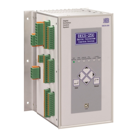
Page 13: Controls And Indicators
(LCD). Front Panel Illustration and Description DECS-250 controls and indicators are illustrated in Figure 2 and described in Table 1. The locators and descriptions of Table 1 correspond to the locators shown in Figure 2. Figure 2. Front Panel Controls and Indicators... -
Page 14: Menu Navigation
“bumpless” transfer when changing active modes. Menu Navigation The DECS-250 provides local access to DECS-250 settings and metering values through a menu structure displayed on the front panel LCD. An overview of the menu structure is illustrated in Figure 3. -
Page 15: Adjusting Settings
LCD backlight when no pushbutton activity is seen for the duration of the LCD Backlight Timeout setting Language Language modules are available for the DECS-250. Once a language module is implemented it can be enabled via the Language Selection setting CALL US TODAY... - Page 16 Screen Scrolling The display can be set to automatically scroll through a user-selected list of metered values. This feature is enabled and disabled with the Enable Scroll setting . The rate at which scrolling occurs is configured with the Scroll Time Delay setting Figure 4.
-
Page 17: Power Inputs
During DECS-250 power-up, the optional ICRM prevents damage to the DECS-250 by limiting inrush current to a safe level. When operating power is applied to the DECS-250, the ICRM limits the inrush current by adding a high level of resistance between the DECS-250 and the power source. Once the inrush current subsides, the series resistance diminishes quickly to allow nominal, steady-state current flow. - Page 18 CALL US TODAY CALL US TODAY REQUEST A QUOTE REQUEST A QUOTE SHOP ONLINE SHOP ONLINE 1-888-POWER-58 1-888-POWER-58 parts@genpowerusa.com parts@genpowerusa.com www.genpowerusa.com www.genpowerusa.com...
-
Page 19: Power Stage
F+ and F–. DECS-250 power stage operating power accepts single- or three-phase ac power from a transformer or PMG. DC power from the station batteries or the armature of a dc exciter is also acceptable. Power Stage operating power is applied at terminals A, B, and C. - Page 20 CALL US TODAY CALL US TODAY REQUEST A QUOTE REQUEST A QUOTE SHOP ONLINE SHOP ONLINE 1-888-POWER-58 1-888-POWER-58 parts@genpowerusa.com parts@genpowerusa.com www.genpowerusa.com www.genpowerusa.com...
-
Page 21: Voltage And Current Sensing
DECS-250 terminals CTB+ and CTB–. The DECS-250 is compatible with CTs having 5 Aac or 1 Aac nominal secondary ratings. The DECS-250 uses this secondary rating, along with the CT nominal primary ratings to interpret the sensed current and calculate system parameters. - Page 22 Cross-current compensation (reactive differential) mode allows two or more paralleled generators to share a common load. As shown in Figure 7, each generator is controlled by a DECS-250 using the DECS-250 cross-current compensation input (terminals CCCT+ and CCCT–) and a dedicated, external current transformer (CT) to sense generator current.
-
Page 23: Bus Voltage
These features are discussed in the Synchronizer chapter of this manual. Three-phase bus sensing voltage is applied to DECS-250 terminals B1, B2, and B3. This sensing voltage is typically applied through a user-supplied voltage transformer, but may be applied directly. - Page 24 CALL US TODAY CALL US TODAY REQUEST A QUOTE REQUEST A QUOTE SHOP ONLINE SHOP ONLINE 1-888-POWER-58 1-888-POWER-58 parts@genpowerusa.com parts@genpowerusa.com www.genpowerusa.com www.genpowerusa.com...
-
Page 25: Synchronizer
Two modes of generator synchronization are available: phase lock loop and anticipatory . In either mode, the DECS-250 matches the voltage, phase angle, and frequency of the generator with the bus and then connects the generator to the bus by closing the generator breaker. Anticipatory mode has the added capability of compensating for the breaker closing time. - Page 26 DECS-250 metered slip angle reads –30°. Equation 1, below, illustrates the DECS-250 slip angle calculation. This means that the generator angle is lagging behind the bus angle by 30° due to transformer phase shift. To compensate for this phase shift, the angle compensation setting should contain a value of 330°.
-
Page 27: Voltage Matching
Figure 12. Breaker Failure When a close command is issued to the breaker, the DECS-250 monitors the breaker status and annunciates a breaker failure if the breaker does not close within the time defined by the breaker close wait delay . -
Page 28: Generator And Bus Condition Detection
HMI Navigation Path: Settings, Sync/Voltage Matching, Bus Condition Detection The DECS-250 monitors the voltage and frequency of the generator and bus for determining when a breaker closure is appropriate. Generator and bus condition detection settings are illustrated in Figure 13. - Page 29 Bus Condition A dead bus is recognized by the DECS-250 when the bus voltage decreases below the dead bus threshold for the duration of the dead bus activation delay...
- Page 30 Figure 13. Generator and Bus Condition Detection Settings Dead Gen Threshold: Adjustable from 0 to 600,000 Vac in 1 Vac increments. Dead Gen Activation Delay: Adjustable from 0.1 to 600 s in 0.1 s increments. Gen Failed Activation Delay: Adjustable from 0.1 to 600 s in 0.1 s increments. Generator Stability Overvoltage Pickup and Dropout: Adjustable from 10 to 600,000 Vac in 1 Vac increments.
-
Page 31: Generator Governor Control
During synchronization, the DECS-250 adjusts the generator voltage and frequency by issuing speed correction signals to the speed governor. Correction signals are issued in the form of DECS-250 output contact closures. These correction signals may be either continuous or proportional . - Page 32 CALL US TODAY CALL US TODAY REQUEST A QUOTE REQUEST A QUOTE SHOP ONLINE SHOP ONLINE 1-888-POWER-58 1-888-POWER-58 parts@genpowerusa.com parts@genpowerusa.com www.genpowerusa.com www.genpowerusa.com...
-
Page 33: Regulation
WECC testing requirements. FVR mode can also be used to smooth the transfer from the active 250 to a secondary DECS. When operating in FVR mode, the DECS-250 regulates the level of field voltage it supplies to the field based on the FVR setpoint . - Page 34 Max (% of rated): Adjustable from 0 to 150% in 0.1% increments. Traverse Rate: Adjustable from 10 to 200 seconds in 1 second increments. When operating in var mode, the DECS-250 regulates the reactive power (var) output of the generator based on the var setpoint .
-
Page 35: Pre-Position Setpoints
Power Factor When operating in Power Factor (PF) mode, the DECS-250 controls the var output of the generator to maintain the Power Factor setpoint as the kW load on the generator varies. The setting range of the PF setpoint is determined by the PF – Leading and PF –... -
Page 36: Transient Boost
The transient excitation boosting function improves response to successive faults by providing increased excitation support. When a simultaneous line current increase and line voltage decrease occurs, the DECS-250 compensates by elevating the voltage setpoint above the nominal setpoint. When the line voltage recovers, the voltage setpoint is restored to the nominal value. -
Page 37: Operation With Paralleled Generators
A Load Share ID setting identifies the DECS-250 as a load sharing unit in the network. Checking a Load Sharing Unit number box allows any DECS-250 load sharing units on the network with that Load Share ID number to share load with the currently connected DECS-250. - Page 38 , line drop compensation can be used to maintain voltage at a load located at a distance from the generator. The DECS-250 achieves this by measuring the line current and calculating the voltage for a specific point on the line. Line drop compensation is applied to both the real and reactive portion of the generator line current.
-
Page 39: Autotracking
Navigation Path: Settings Explorer, Operating Settings, Autotracking HMI Navigation Path: Settings, Operating Settings, Autotracking. Internal regulation mode setpoint tracking is a standard feature on the DECS-250. External setpoint tracking is optional (style xx2xxxx). Autotracking settings are illustrated in Figure 20. -
Page 40: Setpoint Configure
Setpoint Configure When the Auto Save setting is enabled, the DECS-250 automatically saves the active setpoint in one- minute intervals. Otherwise, the setpoint which was last sent to the DECS-250 is retained. Figure 21 illustrates the Setpoint Configure screen. Figure 21. Setpoint Configure Setting... -
Page 41: Auxiliary Control
Minimum and maximum setpoint limits are observed when the With Limit box is checked. Auxiliary Control Gains When a current input type is selected, the input current is converted internally by the DECS-250 into a voltage signal in the range of –10 to +10 Vdc. The DECS-250 uses the following equation when 20.0... -
Page 42: Summing Type
In AVR mode, the auxiliary control signal is multiplied by the AVR gain setting . The result defines the setpoint change as a percentage of the rated generator voltage. For example, applying +10 Vdc with an AVR gain of 1.0 raises the AVR setpoint 10% of rated generator voltage. This example also applies to the following modes. -
Page 43: Contact Inputs And Outputs
Navigation Path: Settings Explorer, Programmable Inputs, Contact Inputs HMI Navigation Path: Not available through HMI. Sixteen contact inputs are provided for initiating DECS-250 actions. Two of the contact inputs are fixed- function inputs: Start and Stop. The remaining 14 contact inputs are programmable. An additional 10 contact inputs are available with the optional Contact Expansion Module (CEM-2020). -
Page 44: Contact Outputs
Navigation Path: Settings Explorer, Programmable Outputs, Contact Outputs HMI Navigation Path: Not available through HMI. DECS-250 contact outputs consist of a dedicated watchdog output and 11 programmable outputs. An additional 18 contact outputs are available with the optional Contact Expansion Module (CEM-2020H). - Page 45 Figure 24. Contact Output Label Text Label Text: Enter a string of up to 64 alphanumeric characters. See Terminals and Connectors for an illustration of the programmable output terminals. Contact output electrical ratings are listed in Specifications. CALL US TODAY CALL US TODAY REQUEST A QUOTE REQUEST A QUOTE...
- Page 46 CALL US TODAY CALL US TODAY REQUEST A QUOTE REQUEST A QUOTE SHOP ONLINE SHOP ONLINE 1-888-POWER-58 1-888-POWER-58 parts@genpowerusa.com parts@genpowerusa.com www.genpowerusa.com www.genpowerusa.com...
-
Page 47: Protection
Several volts per hertz settings enable the DECS-250 to provide flexible generator and generator step-up transformer overexcitation protection. An inverse square timing characteristic is provided through the... - Page 48 Figure 25. V/Hz Characteristic – Time Shown on Vertical Axis Figure 26. V/Hz Characteristic – Time Shown on Horizontal Axis CALL US TODAY CALL US TODAY REQUEST A QUOTE REQUEST A QUOTE SHOP ONLINE SHOP ONLINE 1-888-POWER-58 1-888-POWER-58 parts@genpowerusa.com parts@genpowerusa.com www.genpowerusa.com www.genpowerusa.com...
- Page 49 Figure 27. Overexcitation Protection Settings Definite Time Pickup: Adjustable from 0 or 0.5 to 6.00 in increments of 0.01. Definite Time Delay: Adjustable from 0.05 to 600 seconds in increments of 0.001 seconds. Inverse Time Pickup: Adjustable from 0 or 0.5 to 6.00 in increments of 0.01. Time Dial: Adjustable from 0.0 to 9.9 in increments of 0.1.
- Page 50 The generator voltage is monitored for a loss of sensing (LOS) condition. LOS protection settings are illustrated in Figure 30. In the DECS-250, a loss of sensing event is calculated using sequence components. A loss of sensing event occurs when the positive sequence voltage drops below the balanced...
-
Page 51: Frequency Protection
Figure 30. Loss of Sensing Protection Settings Voltage Balanced Level: Adjustable from 0 to 100% in 0.1% increments. Voltage Unbalanced Level: Adjustable from 0 to 100% in 0.1% increments. Time Delay: Adjustable from 0 to 30 seconds in 0.1 second increments. Transfer to Manual: Select Disabled or Enabled. -
Page 52: Power Protection
Underfrequency An underfrequency condition occurs when the frequency of the generator voltage decreases below the 81U pickup threshold for the duration of the 81U time delay setting . A voltage inhibit setting , expressed as a percentage of the rated generator voltage, can be implemented to prevent an underfrequency trip from occurring during startup when the generator voltage is rising toward the nominal level. - Page 53 See Figure 34 for details. Motor Protection The DECS-250 compares the real power (kW) flowing into the motor with the reactive power (kvar) being supplied. Operation of synchronous motors drawing reactive power from the system can result in overheating in parts of the rotor that do not normally carry current.
- Page 54 Figure 34. Generator Capability Curve vs. 40Q Response Pickup and Trip A loss of excitation condition exists when the level of absorbed vars exceeds the loss of excitation (40Q) threshold for the duration of the 40Q time delay . A time delay setting of zero makes the loss of excitation element instantaneous with no intentional time delay.
-
Page 55: Field Protection
Field Protection BESTCOMSPlus Navigation Path: Settings Explorer, Protection, Field HMI Navigation Path: Settings, Protection, Field Field protection provided by the DECS-250 includes field overvoltage, field overcurrent, an exciter diode monitor, and power input failure. Field Overvoltage A field overvoltage condition occurs when the field voltage exceeds the field overvoltage threshold... - Page 56 0.36 × ���� �������� ( ������ − 1 ���������� ���������� Equation 6. Inverse Field Overcurrent Reset Where: Time = maximum time to reset in seconds reset = time dial setting <0.1, 20> = multiple of pickup <1.03, 205> reset Primary and secondary setting groups provide additional control for two distinct machine operating conditions.
- Page 57 An open exciter diode may not be detected if the generator frequency and operating power frequency are the same and the DECS-250 operating power is supplied by a single-phase source. Three-phase operating power is recommended for reliable open diode detection.
- Page 58 Setting the Pickup Level—Number of Generator Poles Unknown The DECS-250 can detect shorted diode conditions when the number of generator poles is not known. To provide this protection, disable open diode protection, set the pole ratio at zero, and enable shorted diode protection.
-
Page 59: Sync-Check Protection
25 status virtual output asserts. This virtual output can be configured (in BESTlogicPlus) to assert a DECS-250 contact output. This contact output can, in turn, enable the closure of a breaker tying the generator to the bus. -
Page 60: Generator Frequency Less Than 10 Hertz
® Navigation Path: Settings Explorer, Protection, Configurable Protection HMI Navigation Path: Settings, Protection, Configurable Protection The DECS-250 has eight configurable protection elements which can be used to supplement the standard DECS-250 protection. BESTCOMSPlus ® configurable protection settings are illustrated in Figure 41. To... - Page 61 RTD Input 1, 2, 3, 4, 5, 6, 7, or 8 • Thermocouple 1 or 2 Protection can be always enabled or enabled only when the DECS-250 is enabled and supplying excitation . When protection is enabled only in Start mode, an arming time delay can be used to delay protection following the start of excitation.
- Page 62 Figure 41. Configurable Protection Settings Label Text: Accepts a maximum of 16 alphanumeric characters. Param Selection: Select Gen VAB, Gen VBC, Gen VCA, Gen V Average, Bus Freq, Bus VAB, Bus VBC, Bus VCA, Gen Freq, Gen PF, KWH, kvarh, Gen IA, Gen IB, Gen IC, Gen I Average, KW Total, KVA Total, kvar Total, EDM Ripple, Exciter Field Voltage, Exciter Field Current, Auxilary Input Voltage, Auxilary Input Current (mA), Setpoint Position, Tracking Error, Negative Sequence Voltage, Negative Sequence Current, Positive Sequence Voltage,Positive Sequence Current, PSS Output, Analog Input 1, Analog...
-
Page 63: Limiters
When the excitation level exceeds the high level setting, the DECS-250 acts to limit the excitation to the value of the high-level setting. If this level of excitation persists for the duration of the high time setting, the DECS-250 acts to limit the excitation to the value of the low-level setting. - Page 64 DECS-250. The generator is permitted to operate indefinitely with this level of excitation. When the excitation level exceeds the low-level setting for the duration of the medium time setting, the DECS-250 acts to limit the excitation to the value of the low-level setting.
- Page 65 Summing Point OEL Online Medium Level: Adjustable from 0 to 20 Adc in increments of 0.01 Adc. Summing Point OEL Online Medium Time: Adjustable from 0 to 120 s in 1 s increments. Summing Point OEL Online High Level: Adjustable from 0 to 30 Adc for the DECS-250. The setting increment is 0.01 Adc.
- Page 66 Figure 46. Inverse Time Characteristic for Takeover OEL Primary and secondary setting groups provide additional control for two distinct machine operating conditions. Each mode of takeover OEL operation (offline and online) has a low-level , high-level , and time dial setting.
-
Page 67: Underexcitation Limiter
Figure 47. Takeover OEL Settings Takeover OEL Low Level: Adjustable from 0 to 15 Adc in increments of 0.01 Adc. Takeover OEL High Level: Adjustable range varies depending on value of Low Level setting. Takeover OEL Time Dial: Adjustable from 0.1 to 20 in increments of 0.1. Reset Method: Select Inverse, Integrating, or Instantaneous. - Page 68 A user-defined curve can have a maximum of five points . This curve allows the user to match a specific generator characteristic by specifying the coordinates of the intended leading reactive power (kvar) limit at the appropriate real power (kW) level. The levels entered for the user-defined curve are defined for operation at the rated generator voltage.
-
Page 69: Stator Current Limiter
, the DECS-250 annunciates the elevated level. If this condition persists for the duration of the High SCL Time setting, the DECS-250 acts to limit the current to the low-level SCL Setting. The generator is permitted to operate indefinitely at or below the low- level threshold. -
Page 70: Var Limiter
VA rating for the machine. A delay setting establishes a time delay between when the var threshold is exceeded and the DECS-250 acts to limit the var flow. Var limiter settings are illustrated in Figure 52. -
Page 71: Limiter Scaling
HMI Navigation Path: Settings, Operating Settings, Limiters, Scaling Automatic adjustment (scaling) of the overexcitation limiter and stator current limiter is possible through the DECS-250 auxiliary control input. Limiter scaling settings are illustrated in Figure 53. OEL and SCL scaling may be independently enabled and disabled . - Page 72 The adjustment range of the corner frequency and slope settings enables the DECS-250 to precisely match the operating characteristics of the prime mover and the loads being applied to the generator. Corner Frequency 100 % P0004-34.vsd 12-03-01 Nominal...
- Page 73 threshold for volts per hertz limiting, the low limiter setting establishes the minimum threshold for volts per hertz limiting, and the time limiter setting establishes the time delay for limiting. Figure 56. Underfrequency/Volts per Hertz Limiter Settings Limiter Mode: Select UF Limiter or V/Hz Limiter. Underfrequency Limiter Corner Frequency: Adjustable from 40 to 75 Hz in 0.1 Hz increments.
- Page 74 CALL US TODAY CALL US TODAY REQUEST A QUOTE REQUEST A QUOTE SHOP ONLINE SHOP ONLINE 1-888-POWER-58 1-888-POWER-58 parts@genpowerusa.com parts@genpowerusa.com www.genpowerusa.com www.genpowerusa.com...
-
Page 75: Metering
The DECS-250 provides comprehensive metering of internal and system conditions. These capabilities include extensive parameter metering, status indication, reporting, and real-time metering analysis. Metering Explorer DECS-250 metering is accessed through the metering explorer menu on the front panel HMI or the BESTCOMSPlus ®... -
Page 76: Metered Parameters
Dragging the blue square anywhere other than one of the arrow/tab boxes places the selected metering screen as a floating window. Metered Parameters DECS-250 metering categories include generator, power, bus, field, power system stabilizer (PSS), and generator synchronization parameters. Generator BESTCOMSPlus ®... - Page 77 Figure 59. Power Primary-Values Figure 60. Energy ® BESTCOMSPlus Navigation Path: Metering Explorer, Bus HMI Navigation Path: Metering Explorer, Bus Metered bus parameters include the voltage across phases A and B (Vab), phases B and C (Vbc), phases A and C (Vca), and the average bus voltage. The frequency of the bus voltage is also metered. Primary- and per-unit values are available.
- Page 78 Field BESTCOMSPlus Navigation Path: Metering Explorer, Field HMI Navigation Path: Metering Explorer, DECS Output Metered field parameters include the field voltage (Vfd), current (Ifd), and exciter diode ripple. The exciter diode ripple is reported by the exciter diode monitor (EDM) and is reported as a percentage of the induced ripple in the exciter field current.
- Page 79 ® Navigation Path: Metering Explorer, Aux Input HMI Navigation Path: Metering Explorer, Aux Input The control signal applied at the DECS-250 auxiliary control input is indicated on the Aux Input metering screen (Figure 65). As configured in BESTCOMSPlus ® , a dc voltage or dc current signal may be applied.
- Page 80 PF are displayed, as well as Alarm status, PSS status, and Null Balance status. Figure 67. Control Panel Start/Stop Mode: Two indicators show the start/stop mode of the DECS-250. When a mode is active, its corresponding indicator changes from gray to green. To select the DECS-250 Start status, click the Start button.
- Page 81 Setpoint Pre-position: A control button and indicator is provided for the three setpoint pre-positions. Clicking the Set 1 button adjusts the excitation setpoint to the Pre-position 1 value and changes the Pre- position 1 indicator to green. Pre-positions 2 and 3 are selected by clicking either the Set 2 or Set 3 button.
-
Page 82: Status Indication
Figure 68. Metering Summary Screen Status Indication Status indication is provided for DECS-250 system functions, inputs, outputs, configurable protection, alarms, and the real-time clock. System Status BESTCOMSPlus ® Navigation Path: Metering Explorer, Status, System Status HMI Navigation Path: Metering Explorer, Status, System Status When any of the system functions illustrated in Figure 69 are active, the corresponding indicator changes from gray to green. - Page 83 Annunciation is also provided for the optional Analog Expansion Module (AEM-2020) inputs. DECS-250 Contact Inputs Status indication for the DECS-250’s 16 contact sensing inputs is provided on the BESTCOMSPlus™ contact inputs screen illustrated in Figure 70. An indicator changes from gray to red when a closed contact is sensed at the corresponding input.
- Page 84 Module (AEM-2020) analog outputs. DECS-250 Contact Outputs Status indication for the DECS-250’s Watchdog and 11 contact outputs is provided on the BESTCOMSPlus contact outputs screen illustrated in Figure 71. An indicator changes from gray to green when the corresponding output changes state (Watchdog output) or closes (Output 1 through 11).
- Page 85 Figure 71. DECS-250 Contact Outputs Status Indication Screen Configurable Protection BESTCOMSPlus ® Navigation Path: Metering Explorer, Status, Configurable Protection HMI Navigation Path: Metering Explorer, Status, Configurable Protection Trip status for the eight configurable, supplemental protection elements is annunciated on the BESTCOMSPlus configurable protection screen (Figure 72).
- Page 86 Figure 73. DECS-250 Alarm Annunciation and Reset Screen 27P Protection AEM Input 8 Out of Range 32 Protection AEM Input 8 Threshold 1 Trip AEM Input 8 Threshold 2 Trip 59P Protection AEM Input 8 Threshold 3 Trip 81O Protection...
- Page 87 Configurable Protection 8 Threshold 2 Trip RTD Input 2 Threshold 3 Trip Configurable Protection 8 Threshold 3 Trip RTD Input 2 Threshold 4 Trip Configurable Protection 8 Threshold 4 Trip RTD Input 3 Out of Range Duplicate AEM RTD Input 3 Threshold 1 Trip Duplicate CEM RTD Input 3 Threshold 2 Trip Ethernet Link Lost...
- Page 88 . Customize the reporting style of each alarm by choosing Disabled, Latching, or Non-Latching. Latching alarms are stored in nonvolatile memory and are retained even when control power to the DECS-250 is lost. Active alarms are shown on the front panel LCD and in BESTCOMSPlus ®...
- Page 89 ® Real-Time Clock screen (Figure 76). Manual adjustment of the DECS-250 clock is made by clicking the Edit button. This displays a window where the DECS-250 time and date can be adjusted manually or according to the connected PC clock’s date and time.
-
Page 90: Auto Export Metering
Found under the Tools menu, the auto export metering function is an automated method for saving multiple metering data files at specific intervals over a period of time while connected to a DECS-250. The user specifies the Number of Exports and the Interval between each export. Enter a base filename for the metering data and a folder in which to save. -
Page 91: Event Recorder
HMI Navigation Path: Metering Explorer, Reports, Sequence of Events A sequence of events recorder monitors the internal and external status of the DECS-250. Events are scanned at four millisecond intervals with 1,023 events stored per record. All changes of state that occur during each scan are time- and date-stamped. - Page 92 Data logging may be triggered by mode triggers, logic triggers, level triggers, or manually through BESTCOMSPlus. Mode Triggers Mode triggers initiate data logging as a result of an internal or external DECS-250 status change. A data log can be triggered by any of the following status changes: •...
- Page 93 • Limiter active • Voltage matching enabled or disabled • Primary or secondary DECS selected • PSS enabled or disabled • Auto Sync enabled or disabled • FCR or FVR mode selected • Droop mode enabled or disabled • Network Load Share enabled or disabled •...
- Page 94 selected to trigger a data log. Each parameter has a level trigger enable setting which configures triggering of a data log when the parameter increases above the upper threshold setting or decreases below the lower threshold setting. The parameters available to trigger a data log are listed below. The lower and upper threshold of each parameter has a setting range of –2 to +2 with an increment of 0.01.
-
Page 95: Trending
® Navigation Path: Settings Explorer, Report Configuration, Trending HMI Navigation Path: Settings, Configuration Settings, Trending The trend log records the activity of DECS-250 parameters over an extended period of time. When enabled , up to six selectable parameters can be monitored over a user-defined duration ranging from one to 720 hours. - Page 96 Figure 82. Trend Log Setup Trending Enable: Select Enabled or Disabled. Trending Log Parameters: Select NO Level Trigger, Vab: PhA-PhB L-L Voltage {p.u}, Vbc: PhB-PhC L-L Voltage {p.u}, Vca: PhC-PhA L-L Voltage {p.u}, Vbus: Bus Voltage {p.u}, Ia : Phase A Current {p.u}, Ib: Phase B Current {p.u}, Ic: Phase C Current {p.u}, Vavg: Avg L-L Voltage {p.u}, Iavg: Avg Line Current {p.u}, Iaux: Cross Current Input {p.u}, Vfd: Field Voltage {p.u}, Ifd: Field Current {p.u}, Vaux: Aux Voltage Input {p.u}, kW: Real Power {p.u.}, kvar: Reactive Power {p.u.}, kVA: Total Power {p.u.}, PF: Power...
-
Page 97: Power System Stabilizer
Power System Stabilizer The optional (style xPxxxxx), integrated power system stabilizer (PSS) is an IEEE type PSS2A, dual- input, “integral of accelerating power” stabilizer that provides supplementary damping for low-frequency, local-mode oscillations and power system oscillations. PSS features include user-selectable, speed-only sensing, two- or three-wattmeter power measurement, optional frequency-based operation, and generator and motor control modes. - Page 98 Test signal input of comp frequency Disable Mechanical ω Frequency Frequency Σ Σ Σ Low-Pass Power Ramp ω Washout Filter Washout Filter COMP Filter Low-Pass Tracking Filter Enable SSW 0 Filter Power Test signal input of electric power Input Scalar SSW 1 Power Power...
- Page 99 However, this may not be the case during low frequency transients, due to the voltage drop across the machine reactance. To compensate for this effect, the DECS-250 first calculates the terminal voltages and currents. It then adds the voltage drop across the quadrature reactance to the terminal voltages to obtain internal machine voltages.
- Page 100 SSW 1 / 2H Enable Washed Out Power Power 1+ sT 1+ sT 1+ sT Disable P0026-14 PSS Power Input Signal Figure 85. Generator Electrical Power Signal After high-pass filtering, the electrical power signal is integrated and scaled, combining the generator inertia constant (2H) with the speed signal.
- Page 101 SSW 2 SSW 3 Derived Stabilizing Speed Signal Deviation Washed Out Speed P0026-19 12-09-04 Washed Out Power Figure 87. Stabilizing Signal Selection Torsional Filters Two torsional filters, shown in Figure 88, are available after the stabilizing signal and before the phase compensation blocks.
- Page 102 The logic limiter compares the signal from the washout filter with the logic limiter upper and lower limit settings. If the counter reaches the set delay time , the time constant for the washout filter changes from the normal time constant to the limit time constant. When the signal returns to within the specified limits, the counter resets and the washout filter time constant changes back to the normal time constant.
- Page 103 generator voltage exceeds the terminal voltage setpoint . The terminal voltage limiter is enabled and disabled by software switch SSW 8 . The limit setpoint is normally selected such that the limiter will eliminate any contribution from the PSS before the timed overvoltage or volts per hertz protection operates.
- Page 104 Figure 94. PSS Parameter Settings CALL US TODAY CALL US TODAY REQUEST A QUOTE REQUEST A QUOTE SHOP ONLINE SHOP ONLINE 1-888-POWER-58 1-888-POWER-58 parts@genpowerusa.com parts@genpowerusa.com www.genpowerusa.com www.genpowerusa.com...
- Page 105 Figure 95. PSS Output Limiter Settings PSS Control: Select Check box to enable. Supervisory Function Power-On Threshold: Adjustable from 0 to 1 in 0.01 increments. Supervisory Function Power Hysteresis: Adjustable from 0 to 1 in 0.01 increments. Setting Group Logic: Check box to enable. Power Level Threshold: Adjustable from 0 to 1 in 0.01 increments.
- Page 106 Torsional Filter 1 Software Switch SSW 4: Select Disabled or Enabled. Torsional Filter 2 Software Switch SSW 5: Select Disabled or Enabled. Torsional Filter Zeta Numerator: Adjustable from 0 to 1 in 0.01 increments. Torsional Filter Zeta Denominator: Adjustable from 0 to 1 in 0.01 increments. Torsional Filter Frequency Response Parameter (Wn): Adjustable from 10 to 150 in 0.05 increments.
-
Page 107: Stability Tuning
Proportional, Integral, Derivative. The word proportional indicates that the response of the DECS-250 output is proportional or relative to the amount of change observed. Integral means that the DECS-250 output is proportional to the amount of time that a change is observed. Integral action eliminates offset. - Page 108 Figure 96. AVR Stability Settings Gain Option: Select T'do=1.0 Te=0.17, T'do=1.5 Te=0.25, T'do=2.0 Te=0.33, T'do=2.5 Te=0.42, T'do=3.0 Te=0.50, T'do=3.5 Te=0.58, T'do=4.0 Te=0.67, T'do=4.5 Te=0.75, T'do=5.0 Te=0.83, T'do=5.5 Te=0.92, T'do=6.0 Te=1.00, T'do=6.5 Te=1.08, T'do=7.0 Te=1.17, T'do=7.5 Te=1.25, T'do=8.0 Te=1.33, T'do=8.5 Te=1.42, T'do=9.0 Te=1.50, T'do=9.5 Te=1.58, T'do=10.0 Te=1.67, T'do=10.5 Te=1.75, or Custom.
- Page 109 Figure 97. PID Calculator Kp – Proportional Gain: Read-only, calculated gain value. Ki – Integral Gain: Read-only, calculated gain value. Kd – Derivative Gain: Read-only, calculated gain value. T’do – Gen. Time Constant: Select a value within the range of 1 to 15 seconds. Te –...
- Page 110 Figure 98. Auto Tuning Window PID Design Mode: Set to either Pole Zero Cancellation or Pole Placement. Power Input Mode: Set to either PMG External or Shunt. Start Auto Tune Button: Begins the auto tuning process. Save PID Gains Button: Saves the calculated PID gains. The File menu contains options for importing, exporting, and printing a graph (.gph) file.
-
Page 111: Fcr And Fvr Modes
BESTCOMSPlus FCR stability settings and FVR stability settings are illustrated in Figure 101. FCR Mode Stability Settings The DECS-250 bases its field current output upon the following settings. The proportional gain (Kp) is multiplied by the error between the field current setpoint and the actual field current value. -
Page 112: Other Modes And Functions
HMI Navigation Path: Settings, Operating Settings, Gains, Other Gains Settings for stability tuning of the Var and Power Factor modes are provided in the DECS-250 along with settings for stability tuning of limiters, the voltage matching function, and main field voltage response. - Page 113 PID algorithm for the reactive power limiter function. Voltage Matching The integral gain (Ki) adjusts the rate at which the DECS-250 matches the generator voltage to the bus voltage. CALL US TODAY CALL US TODAY...
- Page 114 Figure 102. Other Mode and Function Gain Settings Var Ki – Integral Gain: Adjustable from 0 to 1,000 in 0.001 increments. Var Kg – Loop Gain: Adjustable from 0 to 1,000 in 0.001 increments. PF Ki – Integral Gain: Adjustable from 0 to 1,000 in 0.001 increments. PF Kg –...
-
Page 115: Mounting
Mounting As delivered, the DECS-250 is configured for projection (wall) mounting. Front panel mounting is possible with an optional escutcheon plate mounting kit (DECS-250 P/N 9440311100). Mounting Considerations DECS-250 heat sink orientation necessitates vertical mounting for maximum cooling. Any other mounting angle will reduce heat dissipation and possibly lead to premature failure of critical components. - Page 116 Figure 103. Overall and Projection Mounting Dimensions CALL US TODAY CALL US TODAY REQUEST A QUOTE REQUEST A QUOTE SHOP ONLINE SHOP ONLINE 1-888-POWER-58 1-888-POWER-58 parts@genpowerusa.com parts@genpowerusa.com www.genpowerusa.com www.genpowerusa.com...
- Page 117 Figure 104. DECS-250 Escutcheon Plate Dimensions CALL US TODAY CALL US TODAY REQUEST A QUOTE REQUEST A QUOTE SHOP ONLINE SHOP ONLINE 1-888-POWER-58 1-888-POWER-58 parts@genpowerusa.com parts@genpowerusa.com www.genpowerusa.com www.genpowerusa.com...
- Page 118 Figure 105. Panel Cutting and Drilling Dimensions for DECS-250 Panel Mounting CALL US TODAY CALL US TODAY REQUEST A QUOTE REQUEST A QUOTE SHOP ONLINE SHOP ONLINE 1-888-POWER-58 1-888-POWER-58 parts@genpowerusa.com parts@genpowerusa.com www.genpowerusa.com www.genpowerusa.com...
-
Page 119: Terminals And Connectors
Terminals and Connectors DECS-250 terminals and connectors are located on the left side panel, front panel, and right side panel. DECS-250 terminals consist of single-row, multiple-pin headers that mate with removable connectors wired by the user. DECS-250 connectors vary according to their function and the specified options. - Page 120 START CTA − STOP CTB + IN 1 CTB − CTC + IN 2 CTC − IN 3 CCCT + IN 4 CCCT − IN 5 -- - IN 6 BATT + BATT − WTCHD1 IN 7 WTCHD WTCHD2 IN 8 RLY 1 RLY 1 IN 9...
- Page 121 Description These terminals accept three-phase operating power for the excitation power stage of the DECS-250. A ground for the operating power connections is provided at terminal GND. Excitation power is supplied to the field through the terminals labeled F+ and F–.
- Page 122 IRIG -- - IRIG Figure 107. Right Side Connectors and Terminals CALL US TODAY CALL US TODAY REQUEST A QUOTE REQUEST A QUOTE SHOP ONLINE SHOP ONLINE 1-888-POWER-58 1-888-POWER-58 parts@genpowerusa.com parts@genpowerusa.com www.genpowerusa.com www.genpowerusa.com...
-
Page 123: Terminal Types
(not shown). Terminal Types Spring terminals are supplied on DECS-250 controllers with a style number of xxxSxxx. These removable connectors secure each wire with a spring-loaded contact. Compression terminals are supplied for the operating power terminals (locator A), field power output terminals (locator B), and current sensing terminals (locator C) when a style number of xxxCxxx is specified. - Page 124 CALL US TODAY CALL US TODAY REQUEST A QUOTE REQUEST A QUOTE SHOP ONLINE SHOP ONLINE 1-888-POWER-58 1-888-POWER-58 parts@genpowerusa.com parts@genpowerusa.com www.genpowerusa.com www.genpowerusa.com...
-
Page 125: Typical Connections
Typical Connections Typical connection diagrams are provided in this chapter as a guide when wiring the DECS-250 for communication, contact inputs, contact outputs, sensing, and operating power. Typical connections for applications which use three-phase wye generator voltage sensing are illustrated in Figure 108. - Page 126 Figure 108. Typical DECS-250 Connections CALL US TODAY CALL US TODAY REQUEST A QUOTE REQUEST A QUOTE SHOP ONLINE SHOP ONLINE 1-888-POWER-58 1-888-POWER-58 parts@genpowerusa.com parts@genpowerusa.com www.genpowerusa.com www.genpowerusa.com...
- Page 127 Figure 109. Typical DECS-250 PMG Connections CALL US TODAY CALL US TODAY REQUEST A QUOTE REQUEST A QUOTE SHOP ONLINE SHOP ONLINE 1-888-POWER-58 1-888-POWER-58 parts@genpowerusa.com parts@genpowerusa.com www.genpowerusa.com www.genpowerusa.com...
- Page 128 CALL US TODAY CALL US TODAY REQUEST A QUOTE REQUEST A QUOTE SHOP ONLINE SHOP ONLINE 1-888-POWER-58 1-888-POWER-58 parts@genpowerusa.com parts@genpowerusa.com www.genpowerusa.com www.genpowerusa.com...
-
Page 129: Bestcomsplus
DECS-250 is brought into BESTCOMSPlus by downloading settings and logic from the DECS-250. This gives the user the option of developing a custom setting file by modifying the default logic scheme or by building a unique scheme from scratch. -
Page 130: Installation
BESTCOMSPlus. Manual activation is useful if you want to create a settings file prior to receiving your digital excitation system. Note that if a DECS-250 is not connected, you will not be able to configure certain Ethernet settings. Ethernet settings can be changed only when an active USB or Ethernet connection is present. - Page 131 Windows will notify you when installation is complete. Connect a USB cable between the PC and your DECS-250. Apply operating power (per style chart in the Introduction section) to the DECS-250 at rear terminals A, B, and C. Wait until the boot sequence is complete.
- Page 132 The BESTCOMSPlus ® platform window opens. Select New Connection from the Communication pull- down menu and select DECS-250. See Figure 113. The DECS-250 plugin is activated automatically after connecting to a DECS-250. Figure 113. Communication Pull-Down Menu The DECS-250 Connection screen shown in Figure 114 appears. Select USB Connection and click Connect.
- Page 133 Manual activation of the DECS-250 plugin is required only if your initial use of BESTCOMSPlus ® will be on a PC that is not connected to a DECS-250. Manual activation is described in the following paragraphs. Requesting an Activation Key When initially running the DECS-250 plugin, the Activate Device Plugin pop-up appears. You must contact Basler Electric for an activation key before you can activate the DECS-250 plugin.
-
Page 134: Menu Bars
Select DECS-250 from the Device pull-down menu. Enter your Email Address and Activation Key provided by Basler Electric. If you received an email containing the Activation Key, you can select all of the text in the email and copy it to the Windows clipboard using normal Windows techniques. The Get Data button extracts the Device, Email Address, and Activation Key from the Windows clipboard and pastes it into the appropriate fields. - Page 135 Recent Files Open a previously opened file Exit Close BESTCOMSPlus program Communication New Connection Choose new device or DECS-250 Close Connection Close communication between BESTCOMSPlus and DECS-250 Download Settings and Logic from Download operational and logic settings from the device...
-
Page 136: Settings Explorer
DECS-250. Settings Explorer ® The Settings Explorer is a convenient tool within BESTCOMSPlus used to navigate through the various settings screens of the DECS-250 plugin. Descriptions of these configuration settings are organized as follows: • General Settings •... -
Page 137: Metering Explorer
Upload Settings and/or Logic to Device To upload a settings file to the DECS-250, open the file or create a new file through BESTCOMSPlus. Then pull down the Communication menu and select Upload Settings and Logic to Device. If you want to upload operational settings without logic, select Upload Settings to Device. - Page 138 Printing a Settings File To view a preview of the settings printout, select Print Preview from the File pull-down menu. To print the settings, select the printer icon in the upper left corner of the Print Preview screen. You can skip the print preview and go directly to print by pulling down the File menu and selecting Print. A Print dialog box opens with the typical Windows choice to setup the properties of printer.
-
Page 139: Automatic Metering Export
The auto export metering function automatically exports metering data over a user-defined period when a DECS-250 connection is active. The user specifies the Number of Exports and the Interval between each export. Enter a filename for the metering data and a folder in which to save. The first export is performed immediately after clicking the Start button. -
Page 140: Firmware Updates
Figure 120. Auto Export Metering Screen Firmware Updates Future enhancements to the DECS-250 functionality may require a firmware update. Because default settings are loaded when DECS-250 firmware is updated, your settings should be saved in a file prior to upgrading firmware. Warning! Before performing any maintenance procedures, remove the DECS- 250 from service. - Page 141 2020), and the optional Analog Expansion Module (AEM-2020). Embedded firmware is the operating program that controls the actions of the DECS-250. The DECS-250 stores firmware in nonvolatile flash memory that can be reprogrammed through the communication ports. It is not necessary to replace EPROM chips when updating the firmware with a newer version.
- Page 142 Uploader screen and disconnect communication to the DECS-250. Upgrading Firmware in the DECS-250 The following procedure is used to upgrade firmware in the DECS-250. This must be completed after upgrading firmware in any expansion modules. Remove the DECS-250 from service. Refer to the appropriate site schematics to ensure that all steps have been taken to properly and completely de-energize the DECS-250.
-
Page 143: Bestcomsplus Updates
General Settings > Style Number in BESTCOMSPlus. If the style number of the settings file does not match that of the DECS-250 into which it is to be loaded, disconnect from the DECS-250, then modify the style number in the settings file. - Page 144 CALL US TODAY CALL US TODAY REQUEST A QUOTE REQUEST A QUOTE SHOP ONLINE SHOP ONLINE 1-888-POWER-58 1-888-POWER-58 parts@genpowerusa.com parts@genpowerusa.com www.genpowerusa.com www.genpowerusa.com...
-
Page 145: Bestlogic™Plus
DECS-250. The default logic schemes can also be customized to suit your application. Detailed information about logic schemes is provided later in this section. - Page 146 Figure 122. BESTlogicPlus Programmable Logic Tree Branch BESTlogic™Plus Composition There are three main groups of objects used for programming BESTlogicPlus. These groups are I/O, Components, and Elements. For details on how these objects are used to program BESTlogicPlus, see the paragraphs on Programming BESTlogicPlus. This group contains Input Objects, Output Objects, Off-Page Objects, and Alarms.
- Page 147 Name Description Symbol Remote Inputs IN15 - IN24 True when Remote Input x is active. (Available when an optional CEM-2020 is connected.) Virtual Inputs VIN1 - VIN6 True when Virtual Input x is active. Status Inputs Anticipatory True when Anticipatory is selected. Sync Selected (Synchronizer screen) Auto Mode...
- Page 148 Name Description Symbol Gen Breaker Fail The generator breaker did not open in the to Open close wait time period. (Available when the controller is equipped with the optional Auto synchronizer, style number xxxxAxx) Gen Breaker Fail The generator breaker did not close in the to Close close wait time period.
- Page 149 True when the frequency is out of range for Failed (Optional) a length of time calculated internally by the DECS-250 and the PSS is active. PSS Test On True when the power system stabilizer test signal (Frequency Response) is active.
- Page 150 Contact Contact Expansion Module Connected. Expansion True when an optional CEM-2020 is Module, CEM connected to the DECS-250. Connected Contact True when there is no communication from Expansion the CEM. Module, Comms...
- Page 151 Name Description Symbol Analog Analog Expansion Module Connected. Expansion True when an optional AEM-2020 is Module, connected to the DECS-250. Connected Analog True when there is no communication from Expansion the AEM. Module, Comms Failure Analog True when more than one AEM is Expansion detected.
- Page 152 Name Description Symbol Analog There are four thresholds for both of the Expansion Remote Thermocouple Input blocks. Each Module threshold has a separate logic block for the pickup and the trip. Remote Thermocouple Remote Input #1 with its Threshold #1 Pickup and Thermocouple Trip blocks is shown to the right.
- Page 153 Name Description Symbol NAND Input Output Input Output Input Output Input Output XNOR Input Output Input Output (INVERTER) Rising Edge The output is true when the rising edge of a pulse is detected on the input signal. Falling Edge The output is true when the falling edge of a pulse is detected on the input signal.
- Page 154 Name Description Symbol Latches Reset Priority When the Set input is on and the Reset input is off, the latch Latch will go to the SET (ON) state. When the Reset input is on and the Set input is off, the latch will go to the RESET (OFF) state.
- Page 155 Open: This output is pulsed TRUE (closes the output When the contact input is closed, the contact it is mapped to) when the DECS-250 is providing a breaker is indicated to be closed. When signal to the breaker to open. It will be a pulse if the Breaker...
- Page 156 When an input to this block is true, load share data received from that unit is ignored by the DECS-250. LOSS OF When true, this element disables the Loss SENSING of Sensing function.
- Page 157 Name Description Symbol MANUAL MODE When true, this element switches the FCR ONLY Manual mode to FCR. NETWORK LOAD When true, this element disables network SHARE DISABLE load sharing. OEL DISABLED IN When true, this element disables OEL MANUAL MODE when the unit is operating in Manual mode.
- Page 158 Name Description Symbol PSS SEQ CNTRL When true, PSS sequence (phase ENABLED rotation) control is enabled. (Available when the controller is equipped with the optional Power System Stabilizer, style number xPxxxxx) PSS OUTPUT When true, this element disables the DISABLE output of the PSS.
-
Page 159: Logic Schemes
The Active Logic Scheme The DECS-250 must have an active logic scheme in order to function. All DECS-250 controllers are delivered with a default, active logic scheme preloaded in memory. The functionality of this logic scheme is similar to the scheme provided with the DECS-200. If the function block configuration and output logic of the default logic scheme meet the requirements of your application, then only the operating settings (system parameters and threshold settings) need to be adjusted before placing the DECS-250 in service. - Page 160 Sending and Retrieving Logic Schemes Retrieving a Logic Scheme from the DECS-250 To retrieve settings from the DECS-250, the DECS-250 must be connected to a computer through a communications port. Once the necessary connections are made, settings can be downloaded from the DECS-250 by selecting Download Settings and Logic on the Communication pull-down menu.
- Page 161 Figure 123. PSS-Disabled Default Logic – Logic Page 1 Tab CALL US TODAY CALL US TODAY REQUEST A QUOTE REQUEST A QUOTE SHOP ONLINE SHOP ONLINE 1-888-POWER-58 1-888-POWER-58 parts@genpowerusa.com parts@genpowerusa.com www.genpowerusa.com www.genpowerusa.com...
- Page 162 Figure 124. PSS-Disabled Default Logic - Logic Page 2 Tab Figure 125. PSS-Disabled Default Logic - Physical Outputs Tab CALL US TODAY CALL US TODAY REQUEST A QUOTE REQUEST A QUOTE SHOP ONLINE SHOP ONLINE 1-888-POWER-58 1-888-POWER-58 parts@genpowerusa.com parts@genpowerusa.com www.genpowerusa.com www.genpowerusa.com...
- Page 163 Figure 126. PSS-Enabled Default Logic - Logic Page 1 Tab Figure 127. PSS-Enabled Default Logic - Logic Page 2 Tab CALL US TODAY CALL US TODAY REQUEST A QUOTE REQUEST A QUOTE SHOP ONLINE SHOP ONLINE 1-888-POWER-58 1-888-POWER-58 parts@genpowerusa.com parts@genpowerusa.com www.genpowerusa.com www.genpowerusa.com...
-
Page 164: Programming Bestlogic™Plus
Use BESTCOMSPlus ® to program BESTlogicPlus. Using BESTlogicPlus is analogous to physically attaching wire between discrete DECS-250 terminals. To program BESTlogicPlus, use the Settings Explorer within BESTCOMSPlus to open the BESTlogicPlus Programmable Logic tree branch as shown in Figure 122. - Page 165 A red X indicates that an object or element is not available per the style number of the DECS-250. The view of the Main Logic and Physical Outputs can be automatically arranged by clicking the right mouse button on the window and selecting Auto-Layout.
-
Page 166: Bestlogic™Plus File Management
After programming BESTlogicPlus settings, click on the Save button to save the settings to memory. Before the new BESTlogicPlus settings can be uploaded to the DECS-250, you must select Save from the File pull-down menu located at the top of the BESTCOMSPlus main shell. This step will save both the BESTlogicPlus settings and the operating settings to a file. -
Page 167: Bestlogic™Plus Examples
Uploading a BESTlogicPlus File To upload a BESTlogicPlus file to the DECS-250, you must first open the file through BESTCOMSPlus® or create the file using BESTCOMSPlus. Then pull down the Communication menu and select Upload Logic. Downloading a BESTlogicPlus File To download a BESTlogicPlus file from the DECS-250, you must pull down the Communication menu and select Download Settings and Logic from Device. - Page 168 Example 2 - AND Gate Connections Figure 133 illustrates a typical AND gate connection. In this example, Output 11 will become active when the bus and the generator are dead. Figure 133. Example 2 - AND Gate Connections CALL US TODAY CALL US TODAY REQUEST A QUOTE REQUEST A QUOTE...
-
Page 169: Communication
All DECS controllers mentioned here use a female DB-9 (RS-232) connector for communication with a second DECS. On the DECS-250, this connector is located on the right side panel and is illustrated in the Terminals and Connectors section of this manual. A five-foot (1.5 meter) cable, part number 9310300032, is available for interconnecting two DECS controllers. -
Page 170: Modbus™ Communication
Navigation Path: Settings Explorer, Communications, Modbus Setup HMI Navigation Path: Not available through HMI. DECS-250 systems support the RS-485 mode and Modbus/TCP (Ethernet) mode at the same time. DECS-250 Modbus communication registers are listed and defined in the Modbus Communication section of this manual. - Page 171 TO RS-422/RS-485 TO DECS-250 DB-37 FEMALE DECS-250 RS485 DECS-250 RS485 4000 ft 1219.2 m maximum DECS-250 RS485 R = Optional terminating resistor 120 ohms, typical Figure 136. Typical RS-485 Connections RS-485 port communication settings are illustrated in Figure 137 and consist of the baud rate...
-
Page 172: Can Communication
(CEM-2020) and analog expansion module (AEM-2020). A second CAN interface (CAN 2) enables the DECS-250 to provide generator and system parameters to a generator controller such as the Basler DGC-2020. CAN 2 also permits DECS-250 setpoint and mode control from an external device connected to the CAN. -
Page 173: Ethernet Communication
The DECS-250 Connection window appears. (Figure 140) If you know the IP address of the DECS-250, click the radio button for the Ethernet Connection IP at the top of the DECS-250 Connection window, enter the address into the fields and click the Connect button. - Page 174 Figure 140. DECS-250 Connection Window Figure 141. Scanning for Connected Devices Figure 142. Device Discovery Window CALL US TODAY CALL US TODAY REQUEST A QUOTE REQUEST A QUOTE SHOP ONLINE SHOP ONLINE 1-888-POWER-58 1-888-POWER-58 parts@genpowerusa.com parts@genpowerusa.com www.genpowerusa.com www.genpowerusa.com...
- Page 175 Device Directory. The Device Directory stores the name, model, and address of devices you have added. Click the radio button for Select Device to Connect to, select the device from the Device Directory list, and click the Connect button at the top of the DECS-250 Connection window.
-
Page 176: Profibus Communication
On units equipped with the PROFIBUS communication protocol (style xxxxxxP), the DECS-250 sends and receives PROFIBUS data through a DB-9 port located on the right side panel. DECS-250 PROFIBUS communication parameters are listed and defined in the PROFIBUS Communication section of this manual. -
Page 177: Configuration
Configuration Before the DECS-250 is placed in service, it must be configured for the controlled equipment and application. Generator, Field, and Bus Ratings BESTCOMSPlus ® Navigation Path: Settings Explorer, System Parameters, Rated Data HMI Navigation Path: Settings, System Parameters, Rated Data Generator, field, and bus rating settings are illustrated in Figure 146. -
Page 178: Bridge
HMI Navigation Path: Settings, System Parameters, Sensing Transformers DECS-250 configuration includes entry of the primary and secondary values for the transformers that supply generator and bus sensing values to the DECS-250. These configuration settings are illustrated in Figure 148. Generator PT... -
Page 179: Startup Functions
Current settings for the generator CT primary and secondary windings establish the nominal CT current values expected by the DECS-250. DECS-250 sensing current can be obtained from a single phase or all three generator phases Bus PT Voltage settings for the bus PT primary... -
Page 180: Device Information
The field flash time defines the maximum length of time that field flashing may be applied during startup. To use the field flashing function, one of the DECS-250 programmable contact outputs must be configured as a field flashing output. Figure 149. Startup Function Settings Soft Start Level (%): Adjustable from 0 to 90% in 1% increments. - Page 181 DECS-250. Product Information Product information for the DECS-250, CEM-2020, and AEM-2020 includes the device model number and serial number Device Identification The user-assigned Device ID can be used to identify DECS-250 controllers in reports and during polling.
-
Page 182: Display Units
® Navigation Path: General Settings, Display Units HMI Navigation Path: N/A When working with DECS-250 settings in BESTCOMSPlus, you have the option of viewing the settings in English or Metric units and as primary units or per-unit values . When per-unit values are selected, settings are entered as per-unit values and BESTCOMSPlus converts the per-unit inputs to high-side values based on the generator rated data. -
Page 183: Security
Security DECS-250 security is provided in the form of passwords which control the type of operations allowed by a particular user. Passwords can be tailored to provide access to specific operations. Additional security is available by controlling the type of operations allowed through certain DECS-250 communication ports. -
Page 184: Port Security
An additional dimension of security is provided by the ability to restrict the control available through the DECS-250 communication ports. At any given time, only one port can be in use with read or higher access. For example, if a user gains settings access at one port, users at other ports will be able to gain no higher than read access until the user with settings access logs off. -
Page 185: Login And Access Controls
In the BESTCOMSPlus settings explorer, select Port Access Setup. This selection is located under General Settings, Device Security Setup. When prompted, enter a username of “A” and a password of “A” and log on. This factory-default username and password allows administrator- level access. - Page 186 Figure 154. Login and Access Control Settings Access Timeout: Adjustable from 10 to 3,600 s in 1 s increments. Login Attempts: Adjustable from 1 to 10 in increments of 1. Login Time Window: Adjustable from 1 to 99,999 s in 1 s increments. Login Lockout Time: Adjustable from 1 to 99,999 s in 1 s increments.
-
Page 187: Timekeeping
HMI Navigation Path: Settings, General Settings, Clock Setup Time and Date Format Clock display settings enable you to configure the time and date reported by the DECS-250 to match the conventions used in your organization/facility. The reported time can be configured for either the 12- or 24-hour format with the Time Format setting. - Page 188 The Time Priority Setup must be used to enable a connected time source. When multiple, time sources are connected, the Time Priority Setup can be used to rank the sources according to their priority. Figure 155. Clock Setup Time Format and Date Format: Time format is 12- or 24-hour mode. Date format is MM-DD-YYYY, DD- MM-YYYY, or YYYY-MM-DD.
- Page 189 DST Stop Hour: Adjustable from hour 0 to 23 in 1 hour increments. DST Stop Minutes: Adjustable from minute 0 to 59 in 1 minute increments. For Fixed Date DST Configuration: DST Stop Month: Select desired month for DST stop. <Day>: Select desired day (number) of month.
- Page 190 CALL US TODAY CALL US TODAY REQUEST A QUOTE REQUEST A QUOTE SHOP ONLINE SHOP ONLINE 1-888-POWER-58 1-888-POWER-58 parts@genpowerusa.com parts@genpowerusa.com www.genpowerusa.com www.genpowerusa.com...
-
Page 191: Testing
Testing Testing of the DECS-250’s regulation and optional power system stabilizer (style XPXXXXX) performance is possible through the integrated analysis tools of BESTCOMSPlus ® Real-Time Metering Analysis BESTCOMSPlus Navigation Path: Metering Explorer, Analysis HMI Navigation Path: Analysis functions are not available through front panel HMI. - Page 192 With the RTM Analysis screen controls, you can: • Select the parameters to be graphed • Adjust the resolution of the graph x axis and the range of the graph y axis • Start and stop plot captures • Open an existing graph file, save a captured plot in a graph file, and print a captured graph Graph Parameters Any two of the following parameters may be selected for plotting in the graph areas.
-
Page 193: Frequency Response
A Bode plot can be printed, opened, and saved in graph (.gph) format. Transfer Function The point in the DECS-250 logic circuitry where a signal is injected for analysis of magnitude and phase responses is selectable. Signal points include PSS Comp Frequency, PSS Electric Power, AVR Summing, AVR PID Input, and Manual PID Input. -
Page 194: Time Response
• kvar: Reactive Power {pu} • Vab: PhA-PhB L-L Voltage {pu} • kW: Real Power {pu} • Var/PfErr • MechP: Filtered Mechanical Power • Var/PfOut • Network Load Share • Var/PfState • NullBalance: Null Balance Level • VarLimOutput: Var Limiter Output •... - Page 195 Signal Input Signal input selections determine the point in the PSS circuitry where the test signal is applied. Test points include AVR Summing, PSS Comp Frequency, PSS Electric Power, PSS Derived Speed, Manual Summing, and var/PF. A time delay is provided to delay the start of a PSS test after the Time Response screen Start button is clicked.
-
Page 196: Step Response Analysis
If logging is in progress, another log cannot be triggered. Response characteristics displayed on the Step Response Analysis screen are not automatically updated when the DECS-250 operating mode is switched externally. The screen must be manually updated by exiting and then reopening the screen. -
Page 197: Analysis Options
Figure 159. Step Response Analysis - AVR Tab Var and PF Tabs The var and PF tabs are similar in their controls that enable the application of step changes to their respective setpoints. PF tab controls are illustrated in Figure 160. Var and PF tab controls operate as follows. - Page 198 Figure 161. Analysis Options Screen, Layout Tab Figure 162. Analysis Options Screen, Graph Display Tab CALL US TODAY CALL US TODAY REQUEST A QUOTE REQUEST A QUOTE SHOP ONLINE SHOP ONLINE 1-888-POWER-58 1-888-POWER-58 parts@genpowerusa.com parts@genpowerusa.com www.genpowerusa.com www.genpowerusa.com...
-
Page 199: Can Communication
Contact Expansion Module and Analog Expansion Module for more information. CAN bus interface 2 enables the DECS-250 to provide generator and system parameters to a generator controller such as the Basler DGC-2020. CAN 2 also permits DECS-250 setpoint and mode control from an external device connected to the CAN. - Page 200 Broadcast Name Units Rate 0xFE05 Generator Total Real Power Watts 2452 100 ms Generator Total Apparent Power 2460 0xFF00 Contact I/O Status 100 ms Start Input - Byte 0, bits 0,1 Stop Input - Byte 0, bits 2,3 Input 1 - Byte 0, bits 4,5 Input 2 - Byte 0, bits 6,7 Input 3 - Byte 1, bits 0,1 Input 4 - Byte 1, bits 2,3...
- Page 201 Previously active DTCs are available upon request. Active and previously active DTCs can be cleared on request. Table 16 lists the diagnostic information that the DECS-250 obtains over the CAN bus interface. DTCs are reported in coded diagnostic information that includes the Suspect Parameter Number (SPN), Failure Mode Identifier (FMI), and Occurrence Count (OC) as listed in Table 3.
- Page 202 CALL US TODAY CALL US TODAY REQUEST A QUOTE REQUEST A QUOTE SHOP ONLINE SHOP ONLINE 1-888-POWER-58 1-888-POWER-58 parts@genpowerusa.com parts@genpowerusa.com www.genpowerusa.com www.genpowerusa.com...
-
Page 203: Modbus™ Communication
Modbus communications use a master-slave technique in which only the master can initiate a transaction. This transaction is called a query. When appropriate, a slave (DECS-250) responds to the query. When a Modbus master communicates with a slave, information is provided or requested by the master. -
Page 204: Modbus Modes Of Operation
A standard Modbus network offers the remote terminal unit (RTU) transmission mode and Modbus/TCP mode for communication. DECS-250 systems support the Modbus/TCP mode and RS-485 mode at the same time. To enable editing over Modbus TCP, or RS-485, the unsecured access level for the port must be configured to the appropriate access level. - Page 205 3.5 character times before considering the message complete. Once a valid query is received, the DECS-250 waits a specified amount of time before responding. This time delay is set on the Modbus Setup screen under Communications in BESTCOMSPlus ®...
- Page 206 Any query received that contains a non-existent device address, a framing error, or CRC error is ignored. No response is transmitted. Queries addressed to the DECS-250 with an unsupported function or illegal values in the data block result in an error response message with an exception response code. The exception response codes supported by the DECS-250 are provided in Table 20.
-
Page 207: Detailed Message Query And Response For Rtu Transmission Mode
DECS-250 Modbus™ via Ethernet Modbus can communicate through Ethernet if the IP address of the DECS-250 is configured as described in the Communications section of this manual. Detailed Message Query and Response for RTU Transmission Mode A detailed description of DECS-250 supported message queries and responses is provided in the following paragraphs. - Page 208 If the query is a broadcast (device address = 0), no response message is returned. If the DECS-250 receives this query while in the listen only mode, no response message is generated. Otherwise, a response message identical to the query message is transmitted prior to the communications restart.
- Page 209 Data Block byte count and data. The DECS-250 will perform the write when the device address in query is a broadcast address or the same as the DECS-250 Modbus Unit ID (device address).
-
Page 210: Data Formats
CRC Lo error check Response The response message echoes the Query message after the register has been altered. Data Formats DECS-250 systems support the following data types: • Data types mapped to 2 registers Unsigned Integer 32 (Uint32) Floating Point (Float) Strings maximum 4 characters long (String) •... - Page 211 The floating-point format allows for values ranging from approximately 8.43X10 to 3.38X10 . A floating- point value of all zeroes is the value zero. A floating-point value of all ones (not a number) signifies a value currently not applicable or disabled. Example: The value 95,800 represented in floating-point format is hexadecimal 47BB1C00.
-
Page 212: Secure Decs-250 Login Via Modbus
This field contains a two-byte CRC value for transmission error detection. The master first calculates the CRC and appends it to the query message. The DECS-250 system recalculates the CRC value for the received query and performs a comparison to the query CRC value to determine if a transmission error has occurred. -
Page 213: Modbus Parameters
Modbus Parameters General General parameters are listed in Table 22. Table 22. General Group Parameters Group Name Register Type Bytes Unit Range System Data Model Number 40001 String 0 - 64 System Data App Version Information 40033 String 0 - 64 System Data App Sub-version Version 40065... - Page 214 Group Name Register Type Bytes Unit Range Alarms Real Time Clock Alarm 40900 Uint16 Alarms Date Time Set Alarm 40900 Uint16 Alarms Firmware Change Alarm 40900 Uint16 Alarms Freq out of range alarm 40900 Uint16 Alarms Eth link lost alarm 40900 Uint16 Alarms...
- Page 215 Group Name Register Type Bytes Unit Range DECS Control Autotransfer enable 40902 Uint16 DECS Control Var PF selection 40903 Uint16 DECS Control DECS start stop (external) 40903 Uint16 DECS Control Pre-position 1 active 40903 Uint16 DECS Control Pre-position 2 active 40903 Uint16 DECS Control...
- Page 216 Group Name Register Type Bytes Unit Range Gen Below 10 Hz Block 40905 Uint16 Gen Below 10 Hz Pickup 40905 Uint16 Gen Below 10 Hz Trip 40905 Uint16 Block 40905 Uint16 Pickup 40905 Uint16 Trip 40905 Uint16 Block 40905 Uint16 Pickup 40905 Uint16...
- Page 217 Group Name Register Type Bytes Unit Range Configurable Configurable Protection Threshold 2 Pickup 40907 Uint16 Protection 4 Configurable Configurable Protection Threshold 2 Trip 40907 Uint16 Protection 4 Configurable Configurable Protection Threshold 3 Pickup 40907 Uint16 Protection 4 Configurable Configurable Protection Threshold 3 Trip 40907 Uint16 Protection 4...
- Page 218 Group Name Register Type Bytes Unit Range Configurable Configurable Protection Threshold 2 Trip 40909 Uint16 Protection 8 Configurable Configurable Protection Threshold 3 Pickup 40909 Uint16 Protection 8 Configurable Configurable Protection Threshold 3 Trip 40909 Uint16 Protection 8 Configurable Configurable Protection Threshold 4 Pickup 40909 Uint16 Protection 8...
- Page 219 Group Name Register Type Bytes Unit Range Virtual Switch Virtual Switch 5 40912 Uint16 Virtual Switch Virtual Switch 6 40912 Uint16 DECS Control Manual FCR Only 40912 Uint16 DECS Control Droop Disable 40912 Uint16 DECS Control CC Disable 40912 Uint16 DECS Control Line Drop Disable 40912...
- Page 220 Group Name Register Type Bytes Unit Range Contact Expansion Output 2 40914 Uint16 Module Contact Expansion Output 3 40914 Uint16 Module Contact Expansion Output 4 40914 Uint16 Module Contact Expansion Output 5 40914 Uint16 Module Contact Expansion Output 6 40914 Uint16 Module Contact Expansion...
- Page 221 Group Name Register Type Bytes Unit Range DECS PSS Meter Terminal Frequency Deviation 41004 Float No Unit Compensated Frequency DECS PSS Meter 41006 Float No Unit Deviation DECS PSS Meter PSS output 41008 Float No Unit DECS Regulator Meter Tracking error 41010 Float Percent...
- Page 222 Group Name Register Type Bytes Unit Range Bus Voltage Meter PriAng1 41194 String No Unit 0 - 24 Gen Current Meter Mag1 41206 Float 0 - 2000000000 Gen Current Meter Mag1 41208 Float 0 - 2000000000 Gen Current Meter Mag1 41210 Float 0 - 2000000000...
- Page 223 Group Name Register Type Bytes Unit Range Sync Meter1 Slip Angle 41340 Float Degree -359.9 – 359.9 Sync Meter1 Slip Frequency 41342 Float Hertz Sync Meter1 Voltage Difference 41344 Float Volt GENFREQUENCYMETER1 Frequency 41346 Float Hertz 10 - 180 BUSFREQUENCYMETER1 Frequency 41348 Float...
- Page 224 Name Register Type Bytes Unit Range OEL Primary Time Mid 41708 Float Second 0 - 120 OEL Primary Current Hi Off 41710 Float 0 - 30 OEL Primary Current Lo Off 41712 Float 0 - 15 OEL Primary Current Time Off 41714 Float Second...
- Page 225 Name Register Type Bytes Unit Range OEL Scale Takeover Scale 3 41772 Float Percent 0 – 200 Limiter Adjustment range is determined by Scale register 41760. OEL Scale Summing Signal 1 41774 Float Volt -10 – 10 V when 41760 = 1 or Deg F -58 –...
- Page 226 Name Register Type Bytes Unit Range Disabled=0 Auxiliary Input=1 AEM RTD 1=2 AEM RTD 2=3 AEM RTD 3=4 SCL Scale Enable 41846 Uint32 AEM RTD 4=5 AEM RTD 5=6 AEM RTD 6=7 AEM RTD 7=8 AEM RTD 8=9 Limiter Adjustment range is determined by Scale register 41846.
- Page 227 Name Register Type Bytes Unit Range Field Current Regulation Pre-position 42208 Uint32 Maintain=0 Release=1 Mode 2 Setpoint adjustment range Field Current Regulation Pre-position 42210 Float determined by registers 42212 and 42214. Field Current Regulation Minimum 42212 Float Percent 0 – 120 Setpoint Limit Field Current Regulation Maximum 42214...
- Page 228 Name Register Type Bytes Unit Range FVR Traverse Rate 42266 Float Second 10 – 200 FVR Pre-position Mode 1 42268 Uint32 Maintain=0 Release=1 Setpoint adjustment range FVR Pre-position 1 42270 Float Volt determined by registers 42276 and 42278. FVR Pre-position Mode 2 42272 Uint32 Maintain=0 Release=1...
- Page 229 Name Register Type Bytes Unit Range Transient Boost, Voltage Setpoint 42324 Float Percent 0 – 100 Boosting Level Transient Boost, Clearing Voltage 42326 Float Percent 0 – 50 Threshold Transient Boost, Clearing Voltage 42328 Float Second 0 – 1 Delay Global Settings Table 28.
- Page 230 Group Name Register Type Bytes Unit Range Synchronizer Sync Speed Gain 42466 Float No Unit 0.001 - 1000 Synchronizer Sync Voltage Gain 42468 Float No Unit 0.001 - 1000 Synchronizer Voltage Window 42470 Float 2 - 15 Sys Option Input AutoSync Disabled=0 Synchronizer 42472...
- Page 231 Group Name Register Type Bytes Unit Range DECS Control Start Stop Request 42638 Uint32 Stop=0 =1 Start =2 DECS Control Sys Option Underfrequency Hz 42640 Float Hertz 40 - 75 DECS Control Sys Input COM Port Manual Enabled 42642 Uint32 Manual=1 Automatic=2 DECS Control Sys Input COM Port PF var Enabled...
- Page 232 Group Name Register Type Unit Range Exciter Diode Exciter Open Diode Time Delay 43132 Float 10 – 60 Monitor Exciter Diode Exciter Shorted Diode Pickup 43134 Float 0 - 100 Monitor Exciter Diode Exciter Shorted Diode Time Delay 43136 Float 5 –...
- Page 233 Group Name Register Type Unit Range Primary Mode 43214 Uint32 Disabled=0 Under=2 Primary Pickup 43216 Float Disabled=0, 30 - 70 Primary Time Delay 43218 Float 100 - 300000 Primary Voltage Inhibit 43220 Float Disabled=0, 50 - 100 Secondary Mode 43222 Uint32 Disabled=0 Under=2 Secondary Pickup...
- Page 234 Gains Settings Table 31. Gains Settings Group Parameters Name Register Type Bytes Unit Range T'do=1.0 Te=0.17=1 T'do=1.5 Te=0.25=2 T'do=2.0 Te=0.33=3 T'do=2.5 Te=0.42=4 T'do=3.0 Te=0.50=5 T'do=3.5 Te=0.58=6 T'do=4.0 Te=0.67=7 T'do=4.5 Te=0.75=8 T'do=5.0 Te=0.83=9 T'do=5.5 Te=0.92=10 Primary Gain Option 43800 Uint32 T'do=6.0 Te=1.00=11 T'do=6.5 Te=1.08=12 T'do=7.0 Te=1.17=13 T'do=7.5 Te=1.25=14 T'do=8.0 Te=1.33=15 T'do=8.5 Te=1.42=16 T'do=9.0 Te=1.50=17 T'do=9.5 Te=1.58=18 T'do=10.0 Te=1.67=19 T'do=10.5 Te=1.75=20...
- Page 235 Name Register Type Bytes Unit Range Var Limit Ki 43862 Float No Unit 0 - 1000 Var Limit Kg 43864 Float No Unit 0 - 1000 AVR Pri Ka 43866 Float No Unit 0 - 1 AVR Secondary Ka 43868 Float No Unit 0 - 1...
- Page 236 Name Register Type Bytes Unit Range Boot Program Version Char 6 47049 Uint8 No Unit Boot Program Version Char 7 47050 Uint8 No Unit Boot Program Version Char 8 47051 Uint8 No Unit Reserved 47052-64 Uint8 No Unit 0 - 255 RMS Generator Volts Phase A 47251 Float...
- Page 237 47507 Float No Unit 1 - 99999 Rating Generator CT Secondary 47509 Int32 1=1 5=5 Current Rating Not used in DECS-250 47511 Float No Unit Reserved Float 1 47513 Float No Unit 0 - 10000 Bus Sensing PT Primary Rating...
- Page 238 Name Register Type Bytes Unit Range Auxiliary Input Summing Mode 47544 Uint16 Voltage=0 Var=1 Not used in DECS-250 47545 Uint16 No Unit Reserved 8 47546 Uint16 No Unit Auxiliary Input Mode 47547 Uint16 Voltage=0 Current=1 For Future Use 47548 Uint16...
- Page 239 Name Register Type Bytes Unit Range Reserved 10 47587-620 No Unit Filler Setpoint adjustment range determined by FCR Mode Setpoint 47621 Float registers 47655 and 47663. Setpoint adjustment range determined by AVR Mode Setpoint 47623 Float Volt registers 47657 and 47665. Setpoint adjustment range determined by Var Mode Setpoint in kvar 47625...
- Page 240 Name Register Type Bytes Unit Range Step Size for AVR Adjustable 47689 Float No Unit Step Size for Var Adjustable 47691 Float No Unit Step Size for PF Adjustable Max 47693 Float No Unit FCR Pre-Position Mode 47695 Uint16 Maintain=0 Release=1 AVR Pre-Position Mode 47696 Uint16...
- Page 241 Name Register Type Bytes Unit Range First UEL Point kW Value 47819 Float KiloWatt 0 – 1.5 • Rated kVA Second UEL Point kW Value 47821 Float KiloWatt 0 – 1.5 • Rated kVA Third UEL Point kW Value 47823 Float KiloWatt 0 –...
- Page 242 Name Register Type Bytes Unit Range T'do=1.0 Te=0.17=1 T'do=1.5 Te=0.25=2 T'do=2.0 Te=0.33=3 T'do=2.5 Te=0.42=4 T'do=3.0 Te=0.50=5 T'do=3.5 Te=0.58=6 T'do=4.0 Te=0.67=7 T'do=4.5 Te=0.75=8 T'do=5.0 Te=0.83=9 T'do=5.5 Te=0.92=10 Secondary Gain Option Index 47893 Uint32 T'do=6.0 Te=1.00=11 T'do=6.5 Te=1.08=12 T'do=7.0 Te=1.17=13 T'do=7.5 Te=1.25=14 T'do=8.0 Te=1.33=15 T'do=8.5 Te=1.42=16 T'do=9.0 Te=1.50=17 T'do=9.5 Te=1.58=18 T'do=10.0 Te=1.67=19 T'do=10.5...
- Page 243 57600 Baud=57600 RS485 Parity 48165 Uint16 Even Parity=0 Odd Parity=1 No Parity=2 RS485 Stop Bits 48166 Uint16 1 Stop Bit=1 2 Stop Bits=2 DECS-250 Polling Address 48167 Uint16 No Unit 1 - 247 Modbus Response Time Delay 48168 Uint16 Millisecond...
- Page 244 CALL US TODAY CALL US TODAY REQUEST A QUOTE REQUEST A QUOTE SHOP ONLINE SHOP ONLINE 1-888-POWER-58 1-888-POWER-58 parts@genpowerusa.com parts@genpowerusa.com www.genpowerusa.com www.genpowerusa.com...
-
Page 245: Profibus Communication
If there are unused bits, they are filled with a value of zero. Parameters of UINT8 type are not affected by the DECS-250 Network Byte Order setting. The examples, below, show the bit packing order for instances 8 (Controller Status Cyclic) and 11 (Local Contact Outputs Cyclic). - Page 246 Table 35 shows the bit number of each parameter in instance 8 and an example packet returned from a DECS-250. Reading a value of 0x02 (0000 0010) for instance 8 indicates that the device is operating in FCR mode.
- Page 247 Table 37 shows the bit number of each parameter in instance 11 and an example packet returned from a DECS-250. Reading a value of 0xA4 06 (1010 0100 0000 0110) for instance 11 indicates that contact outputs 2, 5, 7, 9, and 10 are closed. The first byte is 1010 0100 and the second is 0000 0110.
-
Page 248: Setup
Setup The following steps are provided to assist in setting up the DECS-250 as a slave on a PROFIBUS network. Please refer to the documentation included with your PLC configuration software for installation and operation instructions. Download the DECS-250 GSD file from the Basler website: www.basler.com Using PLC configuration software, import the DECS-250 GSD file. - Page 249 Inst. Instance Name Type Key Name Unit Range Bus Metering Cyclic Float VBC_GG 0 - 2000000000 Bus Metering Cyclic Float VCA_GG 0 - 2000000000 Bus Metering Cyclic Float Freq_GG 10 - 180 Field Metering Cyclic Float VX_GG -1000 - 1000 Field Metering Cyclic Float IX_GG...
- Page 250 Inst. Instance Name Type Key Name Unit Range DECSCONTROL_DECS_ Not in soft start=0, In soft System Status Cyclic UINT8 SOFT_START_ACTIVE start=1 No active alarms=0, Active System Status Cyclic UINT8 ALARMREPORT_ALARMOUTPUT alarms=1 DECSCONTROL_DECS_PF_VAR_ PF/var not enabled via PLC=0, System Status Cyclic UINT8 ENABLE_52_J_K_ PF/var enabled via PLC=1...
- Page 251 Inst. Instance Name Type Key Name Unit Range Settings Group Indicaion DECSCONTROL_DECS_UEL_SELECT_ Primary settings active=0, UINT8 Cyclic SECONDARY_SETTINGS Secondary settings active=1 Settings Group Indicaion DECSCONTROL_DECS_SCL_SELECT_ Primary settings active=0, UINT8 Cyclic SECONDARY_SETTINGS Secondary settings active=1 Settings Group Indicaion DECSCONTROL_DECS_PROTECT_ Primary settings active=0, UINT8 Cyclic SELECT_SECONDARY_SETTINGS...
- Page 252 Inst. Instance Name Type Key Name Unit Range Bus Metering Float VCA_GG (Bus Voltage Magnitude) 0 - 2000000000 Bus Metering Float VAB_GG (Bus Voltage Angle) 0 - 360 Bus Metering Float VBC_GG (Bus Voltage Angle) 0 - 360 Bus Metering Float VCA_GG (Bus Voltage Angle) 0 - 360...
- Page 253 Inst. Instance Name Type Key Name Unit Range DECSCONTROL_DECS_IS_IN_ Not in manual=0, In Control Panel Status UINT8 MANUAL_MODE manual=1 DECSCONTROL_DECS_FCR_ FCR not active=0, FCR Control Panel Status UINT8 CONTROLLER_ACTIVE active=1 DECSCONTROL_DECS_FVR_ FVR not active=0, FVR Control Panel Status UINT8 CONTROLLER_ACTIVE active=1 DECSCONTROL_DECS_VAR_ VAR not active=0, VAR...
- Page 254 Inst. Instance Name Type Key Name Unit Range Active setpoint is not at a pre-position value=0, Active System Status UINT8 DECSCONTROL_DECS_PREPOSITION setpoint is at a pre-position value=1 DECSCONTROL_DECS_VAR_ VAR not active=0, VAR System Status UINT8 CONTROLLER_ACTIVE active=1 DECSCONTROL_DECS_PF_ System Status UINT8 CONTROLLER_ACTIVE PF not active=0, PF active=1...
- Page 255 Inst. Instance Name Type Key Name Unit Range CEM Input Status UINT8 CEM_INPUT_9 Open=0, Closed=1 CEM Input Status UINT8 CEM_INPUT_10 Open=0, Closed=1 AEM Analog Input Meter Float AnalogInput1RawValue_GG V / mA 0 - 10 V or 4 - 20 mA AEM Analog Input Meter Float AnalogInput2RawValue_GG...
- Page 256 Inst. Instance Name Type Key Name Unit Range AEM Analog Input Status UINT8 AEMPROTECTION4_THRESH2_TRIP Not tripped-0, Tripped=1 AEM Analog Input Status UINT8 AEMPROTECTION4_THRESH3_TRIP Not tripped-0, Tripped=1 AEM Analog Input Status UINT8 AEMPROTECTION4_THRESH4_TRIP Not tripped-0, Tripped=1 AEM Analog Input Status UINT8 AEMPROTECTION5_THRESH1_TRIP Not tripped-0, Tripped=1 AEM Analog Input Status...
- Page 257 Inst. Instance Name Type Key Name Unit Range AEMCONFIG_RTD_INPUT_4_ Value in range=0, Value out AEM RTD Input Status UINT8 OUT_OF_RANGE of range=1 AEMCONFIG_RTD_INPUT_5_ Value in range=0, Value out AEM RTD Input Status UINT8 OUT_OF_RANGE of range=1 AEMCONFIG_RTD_INPUT_6_ Value in range=0, Value out AEM RTD Input Status UINT8 OUT_OF_RANGE...
- Page 258 Inst. Instance Name Type Key Name Unit Range AEM TC Input Meter Float ThermInput2ScaledValue_GG Deg F AEMCONFIG_THERMAL_COUPLE_1_ Value in range=0, Value out AEM TC Input Status UINT8 OUT_OF_RANGE of range=1 AEMCONFIG_THERMAL_COUPLE_2_ Value in range=0, Value out AEM TC Input Status UINT8 OUT_OF_RANGE of range=1...
- Page 259 Inst. Instance Name Type Key Name Unit Range CEM Output Status UINT8 CEM_OUTPUT_18 Open=0, Closed=1 CEM Output Status UINT8 CEM_OUTPUT_19 Open=0, Closed=1 CEM Output Status UINT8 CEM_OUTPUT_20 Open=0, Closed=1 CEM Output Status UINT8 CEM_OUTPUT_21 Open=0, Closed=1 CEM Output Status UINT8 CEM_OUTPUT_22 Open=0, Closed=1 CEM Output Status...
- Page 260 Inst. Instance Name Type Key Name Unit Range CONFIGPROT5_ Config. Prot. Status UINT8 CONFPROTTHRESH1TRIP Not tripped=0, Tripped=1 CONFIGPROT5_ Config. Prot. Status UINT8 CONFPROTTHRESH2TRIP Not tripped=0, Tripped=1 CONFIGPROT5_ Config. Prot. Status UINT8 CONFPROTTHRESH3TRIP Not tripped=0, Tripped=1 CONFIGPROT5_ Config. Prot. Status UINT8 CONFPROTTHRESH4TRIP Not tripped=0, Tripped=1 CONFIGPROT6_...
- Page 261 Inst Instance Name Type Key Name Unit Range AEM Device Info String AppBuildDate_GG No Unit Build Date 0 - 25 characters AEM Device Info String SerialNum_GG No Unit Serial 0 - 25 characters AEM Device Info String AppPartNum_GG No Unit App Part Num 0 - 25 characters AEM Device Info...
- Page 262 ExcCur FCR Setpoints Float TraverseRate_GG 10 - 200 FCR Setpoints Float ExcCurSetpoint_GG 0 - 12 ExcCurMinSetpoint FCR Setpoints Float Limit_GG 0 - 120 ExcCurMaxSetpoint FCR Setpoints Float Limit_GG 0 - 120 ExcCur FCR Setpoints Float Preposition1_GG 0 - 12 ExcCur FCR Setpoints Float Preposition2_GG...
- Page 263 GenPfMaxSetpoint PF Setpoints Float Limit_GG -1 - -0.5 PF Setpoints Float GenPfPreposition1_GG 0.5 – -0.5 PF Setpoints Float GenPfPreposition2_GG 0.5 – -0.5 PF Setpoints Float GenPfPreposition3_GG 0.5 – -0.5 Decs_AuxInput Aux Input Settings UINT32 No Unit Mode_GG Voltage=0 Current=1 Decs_AuxSumming Aux Input Settings UINT32 No Unit...
- Page 264 TpdoEQ1pt0_TeEQ0pt17=1 TpdoEQ1pt5_TeEQ0pt25=2 TpdoEQ2pt0_TeEQ0pt33=3 TpdoEQ2pt5_TeEQ0pt42=4 TpdoEQ3pt0_TeEQ0pt50=5 TpdoEQ3pt5_TeEQ0pt58=6 TpdoEQ4pt0_TeEQ0pt67=7 TpdoEQ4pt5_TeEQ0pt75=8 TpdoEQ5pt0_TeEQ0pt83=9 PrimaryGain TpdoEQ5pt5_TeEQ0pt92=10 AVR Gains UINT32 No Unit Option_GG TpdoEQ6pt0_TeEQ1pt00=11 TpdoEQ6pt5_TeEQ1pt08=12 TpdoEQ7pt0_TeEQ1pt17=13 TpdoEQ7pt5_TeEQ1pt25=14 TpdoEQ8pt0_TeEQ1pt33=15 TpdoEQ8pt5_TeEQ1pt42=16 TpdoEQ9pt0_TeEQ1pt50=17 TpdoEQ9pt5_TeEQ1pt58=18 TpdoEQ10pt0_TeEQ1pt67=19 TpdoEQ10pt5_TeEQ1pt75=20 Custom=21 TpdoEQ1pt0_TeEQ0pt17=1 TpdoEQ1pt5_TeEQ0pt25=2 TpdoEQ2pt0_TeEQ0pt33=3 TpdoEQ2pt5_TeEQ0pt42=4 TpdoEQ3pt0_TeEQ0pt50=5 TpdoEQ3pt5_TeEQ0pt58=6 TpdoEQ4pt0_TeEQ0pt67=7 TpdoEQ4pt5_TeEQ0pt75=8 TpdoEQ5pt0_TeEQ0pt83=9 SecondaryGain TpdoEQ5pt5_TeEQ0pt92=10 AVR Gains UINT32 No Unit Option_GG...
- Page 265 FVR Gains Float FvrTd_GG No Unit 0 - 1 FVR Gains Float FvrKg_GG No Unit 0 - 1000 VAR Gains Float VarKi_GG No Unit 0 - 1000 VAR Gains Float VarKg_GG No Unit 0 - 1000 PF Gains Float PfKi_GG No Unit 0 - 1000 PF Gains...
- Page 266 OelPriTakeover OEL Takeover Float CurMinOn_GG 0 - 15 OelPriTakeover OEL Takeover Float No Unit TimeDialOn_GG 0.1 - 20 OelSecTakeover OEL Takeover Float CurMaxOff_GG 0 - 30 OelSecTakeover OEL Takeover Float CurMinOff_GG 0 - 15 OelSecTakeover OEL Takeover Float No Unit TimeDialOff_GG 0.1 - 20 OelSecTakeover...
- Page 267 SCL Settings Float SclPriTimeHi_GG 0 - 60 SclPriNoResponse SCL Settings Float Time_GG 0 - 10 SCL Settings Float SclSecRefHi_GG 0 - 66000 SCL Settings Float SclSecRefLo_GG 0 - 66000 SCL Settings Float SclSecTimeHi_GG 0 - 60 SclSecNoResponse SCL Settings Float Time_GG 0 - 10 SCL Settings...
- Page 268 DISABLED=0 Auxiliary Input=1 AEM RTD 1=2 AEM RTD 2=3 AEM RTD 3=4 SCL Scaling UINT32 SclScaleEnable_GG No Unit AEM RTD 4=5 AEM RTD 5=6 AEM RTD 6=7 AEM RTD 7=8 AEM RTD 8=9 SCL Scaling Float SclScaleSignal1_GG -10 - 10 SCL Scaling Float SclScaleSignal2_GG...
- Page 269 PSS Control UINT32 PssSecSwitch3_GG No Unit Secondary Frequency=0 Der. Speed=1 PSS Control UINT32 PssSecSwitch4_GG No Unit Secondary Power=0 Der. Freq/Speed=1 PSS Control UINT32 PssSecSwitch0_GG No Unit Secondary DISABLED=0 ENABLED=1 PSS Control UINT32 PssSecSwitch1_GG No Unit Secondary DISABLED=0 ENABLED=1 PSS Control UINT32 PssSecSwitch5_GG No Unit...
- Page 270 PSS Parameter Primary Phase Comp Float PssPriT2_GG Float 0.001 - 6 PSS Parameter Primary Phase Comp Float PssPriT3_GG Float 0.001 - 6 PSS Parameter Primary Phase Comp Float PssPriT4_GG Float 0.001 - 6 PSS Parameter Primary Phase Comp Float PssPriT5_GG Float 0.001 - 6 PSS Parameter...
- Page 271 PSS Parameter Secondary Phase Float PssSecT1_GG Comp Float 0.001 - 6 PSS Parameter Secondary Phase Float PssSecT2_GG Comp Float 0.001 - 6 PSS Parameter Secondary Phase Float PssSecT3_GG Comp Float 0.001 - 6 PSS Parameter Secondary Phase Float PssSecT4_GG Comp Float 0.001 - 6 PSS Parameter Secondary Phase...
- Page 272 Synchronizer UINT32 Fgen_GT_Fbus_GG No Unit DISABLED=0 ENABLED=1 Synchronizer UINT32 Vgen_GT_Vbus_GG No Unit DISABLED=0 ENABLED=1 Synchronizer Float SlipFrequency_GG 0.1 - 0.5 Synchronizer Float VoltageWindow_GG 2 - 15 BreakerClosing Synchronizer Float Angle_GG 3 - 20 SyncActivation Synchronizer Float Delay_GG 0.1 - 0.8 SyncFailActivation Synchronizer Float...
- Page 273 Bus Condition GenStableActivation Detection (Gen Float Delay_GG Sensing) 0.1 - 600 Bus Condition GenFailedActivation Detection (Gen Float Delay_GG Sensing) 0.1 - 600 Bus Condition GenStableLowLine Detection (Gen Float No Unit ScaleFactor_GG Sensing) 0.001 - 3 Bus Condition GenStableAlternate Detection (Gen Float Frequency No Unit...
- Page 274 Gen Undervolt Float Pickup_PS 1 - 600000 Gen Undervolt Float Time_Delay_PS 100 - 60000 Gen Overvolt UINT32 Mode_PP No Unit DISABLED=0 ENABLED=1 Gen Overvolt UINT32 Mode_PS No Unit DISABLED=0 ENABLED=1 Gen Overvolt Float Pickup_PP 0 - 600000 Gen Overvolt Float Time_Delay_PP 100 - 60000 Gen Overvolt...
- Page 275 Field Overvolt UINT32 Mode_PS No Unit DISABLED=0 ENABLED=1 Field Overvolt Float Pickup_PP 1 - 325 Field Overvolt Float Time_Delay_PP 200 - 30000 Field Overvolt Float Pickup_PS 1 - 325 Field Overvolt Float Time_Delay_PS 200 - 30000 Field Overcurrent UINT32 Mode_PP No Unit DISABLED=0 ENABLED=1 Field Overcurrent...
- Page 276 Config Prot 1 UINT32 Threshold4Type_GG No Unit Disabled=0 Over=1 Under=2 Config Prot 1 Float Hysteresis_GG 0 - 100 Config Prot 1 Float ArmingDelay_GG 0 - 300 Config Prot 1 Float Threshold1Pickup_GG No Unit -999999 - 999999 Threshold1 Config Prot 1 Float ActivationDelay_GG 0 - 300...
- Page 277 Gen VAB=0 Gen VBC=1 Gen VCA=2 Gen V Average=3 Bus Freq=4 Bus VAB=5 Bus VBC=6 Bus VCA=7 Gen Freq=8 Gen PF=9 KWH=10 KVARH=11 Gen IA=12 Gen IB=13 Gen IC=14 Gen I Average=15 KW Total=16 KVA Total=17 KVAR Total=18 EDM Ripple=19 Exciter Field Voltage=20 Exciter Field Current=21 Auxilary Input Voltage=22 Auxilary Input Current (mA)=23 Setpoint Position=24 Config Prot 3...
- Page 278 Config Prot 4 Float Hysteresis_GG 0 - 100 Config Prot 4 Float ArmingDelay_GG 0 - 300 Config Prot 4 Float Threshold1Pickup_GG No Unit -999999 - 999999 Threshold1 Config Prot 4 Float ActivationDelay_GG 0 - 300 Config Prot 4 Float Threshold2Pickup_GG No Unit -999999 - 999999 Threshold2...
- Page 279 Gen VAB=0 Gen VBC=1 Gen VCA=2 Gen V Average=3 Bus Freq=4 Bus VAB=5 Bus VBC=6 Bus VCA=7 Gen Freq=8 Gen PF=9 KWH=10 KVARH=11 Gen IA=12 Gen IB=13 Gen IC=14 Gen I Average=15 KW Total=16 KVA Total=17 KVAR Total=18 EDM Ripple=19 Exciter Field Voltage=20 Exciter Field Current=21 Auxilary Input Voltage=22 Auxilary Input Current (mA)=23 Setpoint Position=24 Config Prot 6...
- Page 280 Config Prot 7 Float Hysteresis_GG 0 - 100 Config Prot 7 Float ArmingDelay_GG 0 - 300 Config Prot 7 Float Threshold1Pickup_GG No Unit -999999 - 999999 Threshold1 Config Prot 7 Float ActivationDelay_GG 0 - 300 Config Prot 7 Float Threshold2Pickup_GG No Unit -999999 - 999999 Threshold2...
- Page 281 Remote Analog In 1 UINT32 Type_GG No Unit Voltage=0 Current=1 Remote Analog In 1 Float Hysteresis_GG 0 - 100 Remote Analog In 1 Float ArmingDelay_GG 0 - 300 Remote Analog In 1 Float Threshold1Pickup_GG No Unit -9999 - 9999 Threshold1 Remote Analog In 1 Float ActivationDelay_GG...
- Page 282 Remote Analog In 3 UINT32 Threshold1Type_GG No Unit Disabled=0 Over=1 Under=2 Remote Analog In 3 UINT32 Threshold2Type_GG No Unit Disabled=0 Over=1 Under=2 Remote Analog In 3 UINT32 Threshold3Type_GG No Unit Disabled=0 Over=1 Under=2 Remote Analog In 3 UINT32 Threshold4Type_GG No Unit Disabled=0 Over=1 Under=2 Remote Analog In 3 UINT32...
- Page 283 Remote Analog In 4 Float CurrentMax_GG 4 - 20 Remote Analog In 4 Float VoltageMin_GG 0 - 10 Remote Analog In 4 Float VoltageMax_GG 0 - 10 Remote Analog In 5 UINT32 StopModeInhibit_GG No Unit NO=0 YES=1 Remote Analog In 5 UINT32 Threshold1Type_GG No Unit...
- Page 284 Threshold4 Remote Analog In 6 Float ActivationDelay_GG 0 - 300 Remote Analog In 6 Float ParamMin_GG No Unit -9999 - 9999 Remote Analog In 6 Float ParamMax_GG No Unit -9999 - 9999 Remote Analog In 6 Float CurrentMin_GG 4 - 20 Remote Analog In 6 Float CurrentMax_GG...
- Page 285 Threshold2 Remote Analog In 8 Float ActivationDelay_GG 0 - 300 Remote Analog In 8 Float Threshold3Pickup_GG No Unit -9999 - 9999 Threshold3 Remote Analog In 8 Float ActivationDelay_GG 0 - 300 Remote Analog In 8 Float Threshold4Pickup_GG No Unit -9999 - 9999 Threshold4 Remote Analog In 8 Float...
- Page 286 Threshold2 Remote RTD In 2 Float ActivationDelay_GG 0 - 300 Remote RTD In 2 Float Threshold3Pickup_GG Deg F -58 - 482 Threshold3 Remote RTD In 2 Float ActivationDelay_GG 0 - 300 Remote RTD In 2 Float Threshold4Pickup_GG Deg F -58 - 482 Threshold4 Remote RTD In 2 Float...
- Page 287 Remote RTD In 5 UINT32 Type_GG No Unit _10_Ohm_Cu=0 _100_Ohm_Pt=1 Remote RTD In 5 UINT32 StopModeInhibit_GG No Unit NO=0 YES=1 Remote RTD In 5 UINT32 Threshold1Type_GG No Unit Disabled=0 Over=1 Under=2 Remote RTD In 5 UINT32 Threshold2Type_GG No Unit Disabled=0 Over=1 Under=2 Remote RTD In 5 UINT32 Threshold3Type_GG...
- Page 288 Remote RTD In 7 Float CalOffset_GG Deg F -99999 - 99999 Remote RTD In 7 Float Hysteresis_GG 0 - 100 Remote RTD In 7 Float ArmingDelay_GG 0 - 300 Remote RTD In 7 Float Threshold1Pickup_GG Deg F -58 - 482 Threshold1 Remote RTD In 7 Float...
- Page 289 Remote TC In 1 Float Threshold3Pickup_GG Deg F 32 - 2507 Threshold3 Remote TC In 1 Float ActivationDelay_GG 0 - 300 Remote TC In 1 Float Threshold4Pickup_GG Deg F 32 - 2507 Threshold4 Remote TC In 1 Float ActivationDelay_GG 0 - 300 Remote TC In 2 UINT32 StopModeInhibit_GG...
- Page 290 Gen VAB=0 Gen VBC=1 Gen VCA=2 Gen V Average=3 Bus Freq=4 Bus VAB=5 Bus VBC=6 Bus VCA=7 Gen Freq=8 Gen PF=9 KWH=10 KVARH=11 Gen IA=12 Gen IB=13 Gen IC=14 Gen I Average=15 KW Total=16 KVA Total=17 KVAR Total=18 EDM Ripple=19 Exciter Field Voltage=20 Exciter Field Current=21 Auxilary Input Voltage=22 Auxilary Input Current (mA)=23 Setpoint Position=24 Remote Analog Out...
- Page 291 Gen VAB=0 Gen VBC=1 Gen VCA=2 Gen V Average=3 Bus Freq=4 Bus VAB=5 Bus VBC=6 Bus VCA=7 Gen Freq=8 Gen PF=9 KWH=10 KVARH=11 Gen IA=12 Gen IB=13 Gen IC=14 Gen I Average=15 KW Total=16 KVA Total=17 KVAR Total=18 EDM Ripple=19 Exciter Field Voltage=20 Exciter Field Current=21 Auxilary Input Voltage=22 Auxilary Input Current (mA)=23 Setpoint Position=24 Remote Analog Out...
- Page 292 User Programmable ProgrammableAlarm9 Alarms Float Delay_GG 0 - 300 User Programmable ProgrammableAlarm10 Alarms Float Delay_GG 0 - 300 User Programmable ProgrammableAlarm11 Alarms Float Delay_GG 0 - 300 User Programmable ProgrammableAlarm12 Alarms Float Delay_GG 0 - 300 User Programmable ProgrammableAlarm13 Alarms Float Delay_GG 0 - 300...
- Page 293 Counter 6 Output Logic Counters Float No Unit Timeout_GG 0 - 1800 Counter 7 Output Logic Counters Float No Unit Timeout_GG 0 - 1800 Counter 8 Output Logic Counters Float No Unit Timeout_GG 0 - 1800 AEM RTD TC Metric RTD Input 1 Float Deg C...
- Page 294 CALL US TODAY CALL US TODAY REQUEST A QUOTE REQUEST A QUOTE SHOP ONLINE SHOP ONLINE 1-888-POWER-58 1-888-POWER-58 parts@genpowerusa.com parts@genpowerusa.com www.genpowerusa.com www.genpowerusa.com...
-
Page 295: Maintenance
Preventive Maintenance Connections Periodically check the connections of the DECS-250 to ensure they are clean and tight and remove any accumulation of dust. Electrolytic Capacitors The DECS-250 contains long-life aluminum electrolytic capacitors. For a DECS-250 kept in storage as a spare, the life of these capacitors can be maximized by energizing the device for 30 minutes once per year. -
Page 296: Cleaning The Front Panel
DECS-250 Appears Inoperative If the DECS-250 does not power up (no backlighting on front panel display), ensure that the control power applied to the unit (AC input terminals L and N, DC input terminals BATT+ and BATT–) is at the correct level. -
Page 297: Support
If your PF, var, or watt readings are significantly different from the expected readings for a known load, verify that the B-phase current sensing input of the DECS-250 is connected to a CT on phase B and not phases A or C. - Page 298 CALL US TODAY CALL US TODAY REQUEST A QUOTE REQUEST A QUOTE SHOP ONLINE SHOP ONLINE 1-888-POWER-58 1-888-POWER-58 parts@genpowerusa.com parts@genpowerusa.com www.genpowerusa.com www.genpowerusa.com...
-
Page 299: Specifications
Specifications DECS-250 electrical and physical characteristics are listed in the following paragraphs. Operating Power Voltage Range For 32 Vdc Excitation Power: ..56 to 70 Vac For 63 Vdc Excitation Power: ..100 to 139 Vac or 125 Vdc For 125 Vdc Excitation Power: .. 190 to 277 Vac or 250 Vdc Frequency Range: ...... -
Page 300: Generator And Bus Voltage Sensing
Input Range: ........82 to 132 Vac, 50/60 Hz Burden: ..........50 VA DC Input Nominal Input: ........125 Vdc Input Range: ........90 to 150 Vdc Burden: ..........30 W Terminals AC Input: .......... L, N DC Input: .......... BATT+, BATT– Generator and Bus Voltage Sensing Type: .......... -
Page 301: Contact Inputs
In accordance with the guidelines defined in USB standards, the USB port on this device is not isolated. To prevent damage to a connected PC or laptop, the DECS-250 must be properly tied to ground. RS-232 Type: ..........RS-232 (for external autotracking) Interface: .......... -
Page 302: Irig Time Synchronization Input
Interface: .......... RJ45 jack (style xxxxx1x) or locking duplex ST (straight tip) receptacle (style xxxxx2x) Location: ........... Right side panel Controller Area Network (CAN) Type: ..........SAE J1939 message protocol Interface: .......... Spring (style xxxSxxx) or compression (style xxxCxxx) type terminals Location: ........... -
Page 303: Field Power Output
Minimum Field Resistance 32 Vdc Application: ......2.13 Ω 63 Vdc Application: ......4.20 Ω 125 Vdc Application: ......8.33 Ω Regulation FCR Operating Mode Setpoint Range: ....... 0 to 18 Adc, in increments of 0.1% Regulation Accuracy: ....... ±1.0% of the nominal value for 10% of the power input voltage change or 20% of the field resistance change. -
Page 304: Generator Protection Functions
Generator Protection Functions Overvoltage (59) and Undervoltage (27) Pickup Range: ..........1 to 600,000 Vac Increment: ........1 Vac Time Delay Range: ..........0.1 to 60 s Increment: ........0.1 s Loss of Sensing Time Delay Range: ..........0 to 30 s Increment: ........ -
Page 305: Field Protection Functions
Field Protection Functions Field Overvoltage Pickup Range: ..........1 to 325 Vdc Increment: ........1 Vdc Time Delay Range: ..........0.2 to 30 s Increment: ........0.1 s Field Overcurrent Pickup Range: ..........0 to 22 Adc Increment: ........0.1 Adc Time Delay Range: .......... -
Page 306: Startup
Slip Frequency Range: ..........0.01 to 0.5 Hz Increment: ........0.01 Hz Startup Soft Start Level Range: ..........0 to 90% of Rated Gen Voltage Increment: ........1% Soft Start Time Range: ..........1 to 7,200 s Increment: ........1 s Field Flash Dropout Level Range: .......... -
Page 307: Off-Line Overexcitation Limiting
Off-Line Overexcitation Limiting High Current Level Pickup Range: ..........0 to 30 Adc Increment: ........0.1 Adc Time Range: ..........0 to 10 s Increment: ........1 s Low Current Level Pickup Range: ..........0 to 15 Adc Increment: ........0.1 Adc Sequence of Events Recording (SER) Over 1,000 records are stored in nonvolatile memory (retrievable via BESTCOMSPlus ®... -
Page 308: Patent
HALT (Highly Accelerated Life Testing) HALT is used by Basler Electric to prove that our products will provide the user with many years of reliable service. HALT subjects the device to extremes in temperature, shock, and vibration to simulate years of operation, but in a much shorter period. - Page 309 CE Compliance This product has been evaluated and complies with the relevant essential requirements set forth by the EU legislation. EC Directives: • LVD 2014/35/EU • EMC 2004/108/EC Harmonized standards used for evaluation: • EN 50178 – Electronic Equipment for use in Power Installations •...
- Page 310 CALL US TODAY CALL US TODAY REQUEST A QUOTE REQUEST A QUOTE SHOP ONLINE SHOP ONLINE 1-888-POWER-58 1-888-POWER-58 parts@genpowerusa.com parts@genpowerusa.com www.genpowerusa.com www.genpowerusa.com...
-
Page 311: Analog Expansion Module
9440300990 Rev G Analog Expansion Module General Information The optional AEM-2020 is a remote auxiliary device that provides additional DECS-250 analog inputs and outputs. Features The AEM-2020 has the following features: • Eight Analog Inputs • Eight RTD Inputs •... - Page 312 52 to 500 to 52 Hz ...... 5 G peak for 7.5 min. HALT (Highly Accelerated Life Testing) HALT is used by Basler Electric to prove that our products will provide the user with many years of reliable service. HALT subjects the device to extremes in temperature, shock, and vibration to simulate years of operation, but in a much shorter period span.
-
Page 313: Installation
Inspect for damage, and if there is evidence of such, immediately file a claim with the carrier and notify the Basler Electric regional sales office, your sales representative, or a sales representative at Basler Electric, Highland, Illinois USA. - Page 314 Also, the connectors and headers are uniquely keyed to ensure that the connectors mate only with the correct headers. The 12-position connector is not a plug-in connector and is mounted permanently to the board. Analog Expansion Module DECS-250 CALL US TODAY CALL US TODAY REQUEST A QUOTE...
- Page 315 P1- + (BATT+) Positive side of operating power input AEM-2020 Inputs and Outputs Input and output terminals are shown in Figure 166 and listed in Table 41. DECS-250 Analog Expansion Module CALL US TODAY CALL US TODAY REQUEST A QUOTE...
- Page 316 Voltage input connections are shown in Figure 167 and current input connections are shown in Figure 168. When using the current input, AIN V+ and AIN I+ must be tied together. Analog Expansion Module DECS-250 CALL US TODAY CALL US TODAY...
- Page 317 AEM-2020 4 – 20 mA AIN I+ Current – Transducer AIN V+ Figure 168. Analog Inputs - Current Input Connections DECS-250 Analog Expansion Module CALL US TODAY CALL US TODAY REQUEST A QUOTE REQUEST A QUOTE SHOP ONLINE SHOP ONLINE...
- Page 318 These terminals provide communication using the SAE J1939 protocol and provide high-speed communication between the Analog Expansion Module and the DECS-250. Connections between the AEM-2020 and DECS-250 should be made with twisted-pair, shielded cable. CAN bus interface terminals are listed in Table 42. Refer to Figure 171 and Figure 172.
- Page 319 P0064-09 120 ohm 120 ohm Termination Termination Other Devices Figure 172. CAN bus Interface with DECS-250 providing One End of the Bus DECS-250 Analog Expansion Module CALL US TODAY CALL US TODAY REQUEST A QUOTE REQUEST A QUOTE SHOP ONLINE...
-
Page 320: Communications
The analog expansion module must be enabled with the correct J1939 address. A Control Area Network (CAN) is a standard interface that enables communication between the AEM-2020 and the DECS-250. The Remote Module Setup screen is illustrated in Figure 173. - Page 321 (2) When the arming delay is set to a non-zero value, threshold monitoring begins when the arming delay time has expired after system startup is complete. An out-of-range alarm, configured on the Alarm Configuration, Alarms screen in BESTCOMSPlus, alerts the user of an open or DECS-250 Analog Expansion Module CALL US TODAY...
- Page 322 Alarm Configuration, Alarms screen in BESTCOMSPlus, alerts the user of an open or damaged thermocouple input wire. When enabled, Stop Mode Inhibit turns off thermocouple input protection when excitation is stopped. Analog Expansion Module DECS-250 CALL US TODAY CALL US TODAY REQUEST A QUOTE REQUEST A QUOTE...
- Page 323 I/O group in BESTlogicPlus. For more details, refer to the BESTlogicPlus section. BESTCOMSPlus settings for remote analog outputs are illustrated in Figure 177. Remote Analog Output #1 is shown. DECS-250 Analog Expansion Module CALL US TODAY...
-
Page 324: Metering
The value and status of the remote analog inputs are shown on this screen. The status is TRUE when the corresponding LED is green. Refer to Figure 178. Remote Analog Input #1 is shown. Figure 178. Remote Analog Inputs Metering Analog Expansion Module DECS-250 CALL US TODAY CALL US TODAY REQUEST A QUOTE... - Page 325 4 to 20 mA current input). The scaled value is the raw input scaled up to the range specified by the Parameter Minimum and Parameter Maximum value parameters in the Remote Analog Input settings. Refer to Figure 181. DECS-250 Analog Expansion Module CALL US TODAY...
- Page 326 9440300990 Rev G Figure 181. Remote Analog Input Values Metering When connected to a DECS-250, the Calibrate button shown on the Remote Analog Input Values screen opens the Analog Input Temperature Calibration screen shown in Figure 182. This screen is used to calibrate RTD inputs 1 through 8 and thermocouple inputs 1 and 2.
-
Page 327: Maintenance
Preventive maintenance consists of periodically checking that the connections between the AEM-2020 and the system are clean and tight. Analog Expansion Modules are manufactured using state-of-the-art surface-mount technology. As such, Basler Electric recommends that no repair procedures be attempted by anyone other than Basler Electric personnel. - Page 328 9440300990 Rev G Analog Expansion Module DECS-250 CALL US TODAY CALL US TODAY REQUEST A QUOTE REQUEST A QUOTE SHOP ONLINE SHOP ONLINE 1-888-POWER-58 1-888-POWER-58 parts@genpowerusa.com parts@genpowerusa.com www.genpowerusa.com www.genpowerusa.com...
-
Page 329: Contact Expansion Module
Contact Expansion Module General Information The optional CEM-2020 is a remote auxiliary device that provides additional DECS-250 contact inputs and outputs. Two types of modules are available. A standard module (CEM-2020) provides 24 contact outputs and a high current module (CEM-2020H) provides 18 contact outputs. - Page 330 52 to 500 to 52 Hz ...... 5 G peak for 7.5 min. HALT (Highly Accelerated Life Testing) HALT is used by Basler Electric to prove that our products will provide the user with many years of reliable service. HALT subjects the device to extremes in temperature, shock, and vibration to simulate years of operation, but in a much shorter period span.
-
Page 331: Installation
Inspect for damage, and if there is evidence of such, immediately file a claim with the carrier and notify the Basler Electric regional sales office, your sales representative, or a sales representative at Basler Electric, Highland, Illinois USA. - Page 332 Figure 184. CEM-2020 Overall Dimensions See Figure 185 for CEM-2020H overall dimensions. All dimensions are shown in inches with millimeters in parenthesis. CALL US TODAY CALL US TODAY REQUEST A QUOTE REQUEST A QUOTE SHOP ONLINE SHOP ONLINE 1-888-POWER-58 1-888-POWER-58 parts@genpowerusa.com parts@genpowerusa.com www.genpowerusa.com...
- Page 333 Figure 185. CEM-2020H Overall Dimensions Connections Contact Expansion Module connections are dependent on the application. Incorrect wiring may result in damage to the module. NOTE Operating power from the battery must be of the correct polarity. Although reverse polarity will not cause damage, the CEM-2020 will not operate.
- Page 334 Caution By mating conductors of dissimilar metals, galvanic corrosion could occur which deteriorates connections and leads to signal loss. Connector screw terminals accept a maximum wire size of 12 AWG. Maximum screw torque is 5 in-lb (0.56 N•m). Operating Power The Contact Expansion Module operating power input accepts either 12 Vdc or 24 Vdc and tolerates voltage over the range of 6 to 32 Vdc.
- Page 335 Figure 186. CEM-2020 Input Contact and Output Contact Terminals CALL US TODAY CALL US TODAY REQUEST A QUOTE REQUEST A QUOTE SHOP ONLINE SHOP ONLINE 1-888-POWER-58 1-888-POWER-58 parts@genpowerusa.com parts@genpowerusa.com www.genpowerusa.com www.genpowerusa.com...
- Page 336 These terminals provide communication using the SAE J1939 protocol and provide high-speed communication between the Contact Expansion Module and the DECS-250. Connections between the CEM-2020 and DECS-250 should be made with twisted-pair, shielded cable. CAN bus interface terminals are listed in Table 44. Refer to Figure 188 and Figure 189.
- Page 337 CAN-L P0064-07 120 ohm 120 ohm Termination Termination Other Devices Figure 189. CAN bus Interface with DECS-250 providing One End of the Bus CALL US TODAY CALL US TODAY REQUEST A QUOTE REQUEST A QUOTE SHOP ONLINE SHOP ONLINE 1-888-POWER-58 1-888-POWER-58 parts@genpowerusa.com...
-
Page 338: Communications
HMI Navigation Path: Settings, Programmable Inputs, Remote Contact Inputs The CEM-2020 provides 10 programmable contact inputs with the same functionality as the contact inputs on the DECS-250. The label text of each contact input is customizable and accepts an alphanumeric character string with a maximum of 64 characters. - Page 339 The CEM-2020 provides 24 programmable contact outputs with the same functionality as the contact outputs on the DECS-250. Outputs 12 through 23 can carry 1 A. Outputs 24 through 35 can carry 4 A. The CEM-2020H provides 18 programmable contact outputs with the same functionality as the contact outputs on the DECS-250.
-
Page 340: Metering
Preventive maintenance consists of periodically checking that the connections between the CEM-2020 and the system are clean and tight. Contact Expansion Modules are manufactured using state-of-the-art surface-mount technology. As such, Basler Electric recommends that no repair procedures be attempted by anyone other than Basler Electric personnel. -
Page 341: Revision History
Revision History Table 45 provides a historical summary of the changes made to the DECS-250 hardware. Firmware changes are listed in Table 46 and software changes are listed in Table 47. The corresponding revisions made to this instruction manual are summarized in Table 48. Revisions are listed in chronological order. - Page 342 Expanded description of the IRIG decoding setting in Clock Setup. • Minor edits to Modbus™ communication legacy register table. • Added caution statements in several places recommending proper grounding of the DECS-250 when using the non-isolated USB port. E, 12/13 • Improved description of Profibus communication setup. •...
- Page 343 CALL US TODAY CALL US TODAY REQUEST A QUOTE REQUEST A QUOTE SHOP ONLINE SHOP ONLINE 1-888-POWER-58 1-888-POWER-58 parts@genpowerusa.com parts@genpowerusa.com www.genpowerusa.com www.genpowerusa.com...
- Page 344 CALL US TODAY CALL US TODAY REQUEST A QUOTE REQUEST A QUOTE SHOP ONLINE SHOP ONLINE 1-888-POWER-58 1-888-POWER-58 parts@genpowerusa.com parts@genpowerusa.com www.genpowerusa.com www.genpowerusa.com...
Need help?
Do you have a question about the DECS-250 and is the answer not in the manual?
Questions and answers