Table of Contents
Advertisement
OPERATION MANUAL
NOTE:SEE ADDENDUM FOR SPECIFIC EU INFORMATION.
●
To ensure safe operation of the game machine, be sure to read this Operation Manual before use.
●
Keep this Operation Manual in a safe place for quick access whenever needed.
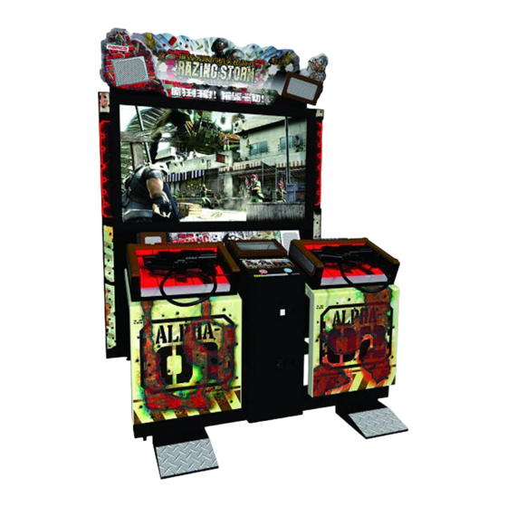
RAZING STORM
The actual product may differ slightly from the illustrations in this manual.
RAZING STORM MANUAL
US/EUROPE
DANGER
R
Advertisement
Table of Contents

Related Manuals for Bandai Namco RAZING STORM


Summary of Contents for Bandai Namco RAZING STORM
- Page 1 RAZING STORM OPERATION MANUAL The actual product may differ slightly from the illustrations in this manual. RAZING STORM MANUAL US/EUROPE NOTE:SEE ADDENDUM FOR SPECIFIC EU INFORMATION. DANGER ● To ensure safe operation of the game machine, be sure to read this Operation Manual before use.
- Page 2 IMPORTANT Read PRECAUTIONS and INSTALLATION Sections before operating game RF Notice Note: This equipment has been tested and found to comply with the limits for a Class A digital device, pursuant to Part 15 of the FCC Rules. These limits are designed to provide reasonable protection against harmful interference when the equipment is operating in a commercial environment.
- Page 3 INTRODUCTION Thank you for purchasing the “Razing Storm” game machine (hereafter referred to as the “machine”). This operation manual describes: How to install, operate, relocate, transport, maintain and discard the machine safely and properly How to operate the machine correctly and make full use of its features ...
- Page 4 Notes:...
-
Page 5: Safety Precautions
1. SAFETY PRECAUTIONS - Be sure to read these instructions to ensure safety - Instructions to the owner If you entrust another party to perform installation, operation, relocation, transportation, maintenance or discarding of the machine, instruct the concerned party to read and observe all the instructions and precautions in this operation manual regarding the particular action to be taken. -
Page 6: Top-Priority Safety Precautions
1. SAFETY PRECAUTIONS- Be sure to read these instructions to ensure safety - 1-3 Top-priority safety precautions WARNING Should any abnormality occur, turn off the power switch immediately to stop operating the machine. Then, unplug the power cord plug from the AC outlet. - Page 7 1. SAFETY PRECAUTIONS- Be sure to read these instructions to ensure safety - ratings. Operate the machine with a power supply voltage in the range of 105 to 125 VAC. Operating the machine with a supply voltage outside the specified range may cause a fire or electric shock.
-
Page 8: Description Of Warning Labels Attached To The Machine
1. SAFETY PRECAUTIONS- Be sure to read these instructions to ensure safety - 1-4 Description of warning labels attached to the machine WARNING The warning labels describe important safety precautions. Observe the following: To ensure that the warning labels attached to the machine are easily ... - Page 9 1. SAFETY PRECAUTIONS- Be sure to read these instructions to ensure safety - Rear side of Coin Tower Assy Coin Tower Assy Warning sticker Maintenance Part No.: RM44-13905-00 * Internal parts refer to the CPU Board, USIO PC Board, GUN DRIVE PC Board, switching regulators and others.
-
Page 10: Table Of Contents
CONTENTS INTRODUCTION 1. SAFETY PRECAUTIONS ........1 - Be sure to read these instructions to ensure safety - 1-1 Magnitudes of risk ..........................1 1-2 Definition of the term "technician" ....................... 1 1-3 Top-priority safety precautions ......................2 1-4 Description of warning labels attached to the machine ..............4 CONTENTS ..........................6 2. SPECIFICATIONS ......................10 3. - Page 11 CONTENTS 7-1-2 Operation check (after power ON) ......................41 7-2 How to play ............................42 7-3 Adjustment ............................44 7-3-1 Adjustment switches ............................ 44 7-3-2 Adjustment of display ..........................45 7-4 Test mode ............................46 7-4-1 Description of the Menu screen ......................... 46 7-4-2 Game fee/free play setting (COIN OPTIONS) ................... 47 7-4-3 Game setting (Game OPTIONS) ........................ 48 7-4-4 Switch input/output tests (I/O TEST) ......................49 (a) I/O PCB CHECK ................................50 (b) GUN INITIALIZE 1P-2P (Gun Assy aim setting 1P-2P) ....................51 (c) SWITCH TEST ................................54 (d) SOLENOID TEST ................................55...
- Page 12 CONTENTS 8-2-4 Control Assy - To be conducted by a technician only - ................76 8-2-5 Gun Assy - To be conducted by a technician only - ................... 77 8-2-6 Pedal Assy - To be conducted by a technician only - ................. 78 8-3 Removing and installing Assys and parts ..................
- Page 13 CONTENTS 10-7 Gun Tower Assy ..........................122 10-8 Gun Assy ............................126 10-9 Pedal Assy ............................ 128 11. WIRING DIAGRAMS ....................131 11-1 Part 1 of 2 - USA Wiring ....................... 131 11-2 Part 2 of 2 - USA Wiring ....................... 132 11-3 Part 1 of 2 - UK Wiring ......................... 133 11-4 Part 2 of 2 - UK Wiring ......................... 134...
-
Page 14: Specifications
2. SPECIFICATIONS (1) Rated power supply US 105-125 VAC 60 Hz - Europe 240V 50/60Hz (2) Rated power consumption 460 W (3) Maximum current consumption 6 Amps (4) Coin box capacity Approx. $750 (3,000 25¢ coins) (5) Display device 60-inch DLP projector (6) Dimensions 1. - Page 15 2. SPECIFICATIONS Control Assy 1,520 (W) x 540 (D) x 1,120 (H) [mm] 1,445 Signboard Assy 1,330 (W) x 390 (D) x 340 (H) [mm] 1,630 Pedal Assy 250 (W) x 250 (D) x 160 (H) [mm] (7) Weight 1. As installed 341 kg 2.
-
Page 16: Checking The Package Contents
3. CHECKING THE PACKAGE CONTENTS The product package shipped from the factory contains the following components and parts. Make sure that all items shown below are contained in the product package. If any item is missing, contact your distributor. Packaging and accessories Projector Tower Assy Control Assy... - Page 17 3. CHECKING THE PACKAGE CONTENTS Accessory list Name Description Qty. Razing Storm Operation Manual (this manual) Projector Adjustment Manual Maintenance key each (total: 4 keys) Coin box key Shared use Coin insertion sticker (A) 1PLAY $1.00 Power cord Flange socket bolt (M8 x 40)
-
Page 18: Overall Construction (Names Of Parts)
4. OVERALL CONSTRUCTION (Names of Parts) Front side Fluorescent lamp LED sensor cover Projector Assy Side Pillar (L) Assy Gun Assy Front plate door Rack Assy Front door Control Assy Pedal Assy Rear side AC Plate Assy Power switch Fuseholder... -
Page 19: Installation
5. INSTALLATION WARNING Install the machine according to the instructions and procedures specified in this operation manual. Failure to follow the specified procedures may result in a fire, electric shock, injury or machine malfunctions. Insert the power cord plug firmly into the AC outlet. Poor contact may cause overheating that can lead to a fire or burns. Be sure to connect the ground lead. If the ground lead is not connected, electric shock can result in case of electrical leakage. (See P. 33 "5-6 Connecting the power cord and ground lead.") Install the machine securely by using the level adjusters. Unstable machine installation can result in an accident or injury. (See P. 22 "5-3-1 Adjusting the level adjusters.") 5-1 Installation conditions 5-1-1 Locations to avoid WARNING The machine is designed for indoor use. Never install the machine outdoors or at any of the following locations: Place in direct sunlight Place exposed to rain or water leakage Damp place Dusty place ... -
Page 20: Play Zone For Installed Machine
5. INSTALLATION 5. INSTALLATION 5-1-2 Play zone for installed machine WARNING Provide a play zone shown below so that players do not accidentally bump into observers or passersby. The distance from the floor to the ceiling must be at least 2 m 40 cm. Provide a space of at least 50 cm between the rear side of the machine and the wall or other machine in order to turn the power switch ON/OFF and open the back door for maintenance. 2m70cm or more 50cm or more 50cm or more Play Zone Aisle... -
Page 21: Prevention Of Communication Interference
5. INSTALLATION 5. INSTALLATION 5-1-3 Prevention of detection interference • If two or more units are installed next to each other, the aim detection systems of the Gun Assys can operate erroneously due to interference. To prevent this, position the game machines (player side) alternately. Using page 49 as a guide, set the Gun Sensor channel of the first game to “1”. -
Page 22: Required Dimensions Of Carry-In Passage (Such As Doors And Corridors)
5. INSTALLATION 5-2 Required dimensions of carry-in passage (such as doors and corridors) The game machine is divided into Assys at the factory before shipment. The size of each Assy is as follows: Projector Tower Assy 1,650 (W) x 710 (D) x 1,870 (H) [mm] Weight: 215 kg Control Assy 1,445 (W) x 920 (D) x 1,050 (H) [mm] Weight: 94 kg Signboard Assy... -
Page 23: Separating The Projector Tower Assy
5. INSTALLATION 5-2-1 Separating the Projector Tower Assy (when required due to passage conditions) - To be conducted by a technician only - * If the carry-in passage is sufficiently tall, the following procedure is not necessary. In that case, proceed to “5-3 Assembly” on page 22. WARNING The projector weighs approximately 31 kg. Removal of the projector should be performed by at least three persons to prevent accidents. Remove the three torx bolts (M5 X 12), then dismount the front plate door. Using the Instructions on P. 79, 8-3-1(1) Replacing the LED Boartd steps through remove the LED Sensor cover from the game. Torx bolt (M5 x 12) Connectors Front plate door... - Page 24 5. INSTALLATION On the pillar, remove the six Torx bolts (M5 x 12) and loosen the bolt on the rear side at the top, then dismount the side pillar cover (R). Disconnect the connector, then remove the four Hex head bolts (with flat and spring washers) (M6 x 20).
- Page 25 5. INSTALLATION While one person disengages and lifts the left pillar approximately 25 cm. remove the top monitor retention bracket. Next, remove the left monitor retention bracket and slide the projection monitor to the players left, thereby clearing the right rentension bracket. Left and Right monitor retention bracket screws Input Signal cover...
-
Page 26: Assembly
5. INSTALLATION 5-3 Assembly 5-3-1 Adjusting the level adjusters After positioning the Projector Assy according to the instructions in “5-1 Installation conditions” on page 15, lower the level adjusters (at 4 locations) until the casters are lifted about 5 mm from the floor (the casters should be able to swivel freely). Approx. -
Page 27: Assembling The Signboard Assy - To Be Conducted By A Technician Only
5. INSTALLATION 5-3-2 Assembling the Signboard Assy - To be conducted by a technician only - WARNING The Signboard Assy weighs approximately 25 kg. The installation task should be performed by at least three persons in a sufficiently large work area to prevent accidents. CAUTION Since the installation of the Signboard Assy must be conducted at a height, prepare a step ladder or platform to stand on. Performing the task in an awkward position can result in injury or machine damage. Using four Torx bolts (M5 x 12) and four flat washers (M5), install the center plate to the front side of the Signboard Assy, making sure that the center plate is positioned on the center plate support. - Page 28 5. INSTALLATION Using four Torx bolts (M5 x 12) and four flat washers (M5), install the side plate (L) to the front side of the left-side speaker. Side plate (L) Flat washers (M5) Torx bolts (M5 x 12) Using two Torx bolts (M5 x 12), install the side plate (R) to the front side of the right- side speaker.
- Page 29 5. INSTALLATION Place the Signboard Assy on the Projector Assy from the front side, making sure that signboard hanger brackets on the top panel of the Projector Assy enter the holes on the bottom surface of the Signboard Assy. Signboard Assy Signboard hanger brackets Move the Signboard Assy toward the back.
- Page 30 5. INSTALLATION Connect the left-side connector of the Signboard Assy, and install the signboard door plate, which was removed in step , with two Torx bolts (M5 x 20). Check the direction and shape of the connector carefully in order to prevent damage to electrical circuits due to incorrect connector connection. Torx bolt (M5 x 10) Connector Signboard Assy Signboard door plate...
-
Page 31: Connecting The Projector Tower Assy And Control Assy
5. INSTALLATION 5-3-3 Connecting the Projector Tower Assy and Control Assy - To be conducted by a technician only - Check the direction and shape of the connector carefully in order to prevent damage to electrical circuits due to incorrect connector connection. Adjust the level adjusters on the Control Assy and align the Projector Tower Assy with the Projector Tower Assy. Secure the Control Assy to the Projector Tower Assy with four flange socket bolts (M8 x 40). - Page 32 5. INSTALLATION Connect the eight connectors. (See the connection diagram below.)Using the nuts mounted to the studs, secure the ground braid and the ground wire (Green-Yellow) from each respective tower to the joint box. Ground wire Ground Braid Connectors Connector Using four Torx bolts (M5 x 12), install the joint box cover which was removed in step To remove, follow the installation sequence in reverse.
-
Page 33: Installing The Pedal Assys - To Be Conducted By A Technician Only
5. INSTALLATION 5-3-4 Installing the Pedal Assys - To be conducted by a technician only - Using four flange socket bolts (M6 x 12) (2 on each side), mount the housing loosely to each Pedal Assy. Flange socket bolts (M6 x 12) (to be tightened loosely) Flange socket bolts (M6 x 12) (to be tightened loosely) Pedal Assy (Elongated hole) Connect the connector and attach the housing of each Pedal Assy to the Control... - Page 34 5. INSTALLATION Press down on the Pedal Assy so that it contacts the floor firmly, and tighten the temporarily installed four flange socket bolts securely. (Make sure that the Pedal Assy is not lifted off the floor.) (Tighten the bolts.) (Tighten the bolts.) To remove, follow the installation sequence in reverse.
-
Page 35: Removing And Installing The Front Door - To Be Conducted By A Technician Only
5. INSTALLATION 5-4 Removing and installing the front door - To be conducted by a technician only - WARNING To protect the service staff and other people from electric shock, accident and injury and to prevent damage to the electric circuitry of the machine, be sure to turn off the power switch before initiating the described task. Remove the two Torx bolts (M5 x 40). Using the provided maintenance key, unlock the lock located at the center of the front door. Dismount the front door. Front door Torx bolt (M5 x 40) To reinstall, follow the removal sequence in reverse. -
Page 36: Inserting The Dongle - To Be Conducted By A Technician Only
5. INSTALLATION 5-5 Inserting the dongle - To be conducted by a technician only - WARNING To protect the service staff and other people from electric shock, accident and injury and to prevent damage to the electric circuitry of the machine, be sure to turn off the power switch before initiating the described task. The game is shipped with the dongle installed, this information is provided for re-installation purposes only. The supplied dongle is designed exclusively for this game machine. Do not use this dongle in any other machine. Also, do not use the dongle of another machine in this game machine. Failure to observe this instruction can result in equipment malfunctions. Be sure to turn off the power switch before inserting the dongle. Make sure that the power switch on the Projector Tower Assy is turned off. Remove the front door. (See P. 31 “5-4 Removing and installing the front door.”) Insert the dongle into the slot on the left side, making sure that the barcode label on the dongle is facing upward. -
Page 37: Connecting The Power Cord And Ground Lead
5. INSTALLATION 5-6 Connecting the power cord and ground lead WARNING Connect the ground lead using one of the following methods. If the machine is not grounded properly, electric shock can occur in case of electrical leakage. (1)Use only the 3P plug for grounding the machine. Do not attempt to defeat this connection. Do not use adaptors. Connect only to a properly grounded outlet. (1) Using 3P AC socket Insert the power cord plug directly into the AC outlet. Power cord plug 3P AC socket... -
Page 38: Optional Dollar Bill Adaptor
5. INSTALLATION 5-7 Optional Dollar Bill Acceptor The Coin Door Assembly used on RAZING STORM is equipped to utilize a dollar bill acceptor. All the required wiring connections are provided inside the game for this application. The Coin Door can accomodate the following Dollar Bill Acceptor: MEI 2000 Series... -
Page 39: Moving And Transporting
6. MOVING AND TRANSPORTING WARNING Do not leave the machine on a slope. If the machine is left on a slope, it may tip over and cause an unexpected accident. 6-1 Moving (on the floor) When moving the machine, separate the machine into the Projector Tower Assy, Control Assy and Pedal Assys. -
Page 40: Transportation
6.MOVING AND TRANSPORTING 6-2 Transportation 6-2-10 Manual transportation (carrying on stairs, etc.) WARNING When moving the machine, be sure to separate the machine into the Projector Assy, Signboard Assy, Control Assy and Pedal Assys. Moving the machine without disassembly can result in an accident or injury. -
Page 41: Loading On Or Unloading From A Vehicle
6.MOVING AND TRANSPORTING 6-2-2 Loading on or unloading from a vehicle WARNING When moving the machine, be sure to separate the machine into the Projector Assy, Signboard Assy, Control Assy and Pedal Assys. Moving the machine without disassembly can result in an accident or injury. (See P. -
Page 42: Trucking
6.MOVING AND TRANSPORTING 6-2-3 Trucking WARNING When transporting the machine on a vehicle, secure the machine to the vehicle in order to prevent it from moving due to acceleration or deceleration of the vehicle. Failure to tie the machine securely to the vehicle may result in an accident. - Page 43 7. OPERATION WARNING Should any abnormality occur, turn off the power switch immediately to stop operating the machine. Then, unplug the power cord plug from the AC outlet. Operating the machine without correcting abnormalities can result in a fire or accident.
-
Page 44: Operation
7. OPERATION 7. OPERATION 7-1 Pre-service check Check the items described below before commencing operation. If any problem is found, take corrective measures by referring to “8-2 Troubleshooting” on page 73. 7-1-1 Safety check (before power ON) WARNING • To prevent accidents and injury, be sure to check the following items before commencing operation. -
Page 45: Operation Check (After Power On)
7. OPERATION 7. OPERATION 7-1-2 Operation check (after power ON) Check the following items after turning on the power switch. (1) Check sound reproduction. (Is sound produced by each speaker?) (See P. 60 “7-4-6 Sound test (SOUND TEST).”) (2) Check the fluorescent lamp in the Signboard Assy. (Is the fluorescent lamp ON?) (3) Check the LED-Edge PC Board. -
Page 46: How To Play
7. OPERATION 7-2 How to play CAUTION If a player becomes sick due to game images or light stimulation, have the person stop playing the game immediately and let him/her rest. In rare cases, stimulation by lights or video images can cause convulsion or a loss of consciousness. - Page 47 7. OPERATION (4) Special weapons When the player’s points reach a certain level, the player’s weapon automatically changes from the machine gun to a different weapon. When this weapon change occurs, a new weapon is shown on the screen. The vibration that the player feels when using the weapon also changes according to the type of weapon used.
-
Page 48: Adjustment
7. OPERATION 7-3 Adjustment 7-3-1 Adjustment switches Open the service door on the Coin Tower Assy to access the adjustment switches. Coin Tower Assy ( a ) SERVICE ( d ) E TE ( c ) SELECT ( b ) TEST CO N METER Service door... -
Page 49: Adjustment Of Display
7. OPERATION 7-3-2 Adjustment of display The projector is adjusted for optimum condition for the game machine before shipment. Ordinarily the projector does not require readjustment at the installation site. Please Note: If the projector does require readjustment, please contact Namco for the appropriate instructions. -
Page 50: Test Mode
7. OPERATION 7-4 Test mode 7-4-1 Description of the Menu screen Open the service door on the Coin Tower Assy and set the Test switch to ON.The Menu screen appears. MENU COIN OPTIONS Setting of game fee,etc. See 7-4-2. GAME OPTIONS Setting of game details See 7-4-3. -
Page 51: Game Fee/Free Play Setting (Coin Options)
7. OPERATION 7-4-2 Game fee/free play setting (COIN OPTIONS) This screen is used to set the game fee and free play option. Select “COIN OPTIONS” in the Menu screen and press the Enter switch. The Coin Options screen appears. COIN OPTIONS [DEFAULT IN GREEN] 4 COIN ( S ) 1 CREDIT GAME COST... -
Page 52: Game Setting (Game Options)
7. OPERATION 7-4-3 Game setting (GAME OPTIONS) This screen is used to set game details. Select “GAME OPTIONS” in the Menu screen and press the Enter switch. The Game Options screen appears. Default settings are shown in green, except for HIT-COLOR. For the HIT-COLOR parameter, GREEN and RED indicate the color of damage display. -
Page 53: Switch Input/Output Tests (I/O Test)
7. OPERATION 7-4-4 Switch input/output tests (I/O TEST) This screen is used to test the switches. Select “I/O TEST” in the Menu screen and press the Enter switch. The I/O Test screen appears. I/O TEST I/O PCB CHECK GUN INITIALIZE 1P GUN INITIALIZE 2P SWITCH TEST SOLENOID TEST... -
Page 54: (A) I/O Pcb Check
7. OPERATION (a) I/O PCB CHECK This screen is used to check the I/O PC Board. I/O TEST I/O PCB : CONNECT OK This screen is used to check the I/O PC Board. BNGI. : US1001 : Ver 1.00 : JPN,Multipurpose with PPG. Indicates the status of the PCB. -
Page 55: (B) Gun Initialize 1P-2P (Gun Assy Aim Setting 1P-2P)
7. OPERATION (b) GUN INITIALIZE 1P-2P (Gun Assy aim setting 1P-2P) This screen is used to adjust the aim of the Gun Assys. Select “GUN INITIALIZE 1P” or “GUN INITIALIZE 2P” in the I/O Test screen and press the Enter switch. The Gun Initialize screen (1) appears. - Page 56 7. OPERATION Press the Service switch (or press the pedal) while the display is showing the Gun Initialize screen (1) to activate to the Gun Initialize screen (2). Then, adjust the aim of the Gun Assy. This mode enables the adjustment of minor deviation resulting from the installation conditions or individual characteristics of the Gun Assy light receiving unit and LED Board.
- Page 57 7. OPERATION To adjust the gun aim, follow the procedure described below. Be sure to hold the Gun Assy straight. Do not tilt the Gun Assy. Hold the Gun Assy toward the screen so that the rear sight notch aligns with ...
-
Page 58: (C) Switch Test
7. OPERATION (c) SWITCH TEST This screen is used to test the switches for proper operation. I/O TEST COIN SERVICE TEST UP SELECT DOWN SELECT GUN TRIGGER 1P GUN TRIGGER 2P FOOT PEDAL 1P FOOT PEDAL 2P 1P START 2P START UP SELECT+ENTER:EXIT Switch Test screen The Switch Test screen shows the statuses of the switches. -
Page 59: (D) Solenoid Test
7. OPERATION (d) SOLENOID TEST I/O TEST SOLENOID TEST PULL GUN TRIGGER TO ACTION EXIT ENTER SW : ENTER Solenoid test screen When the trigger of the Gun Assy is pulled, the vibration of the Gun Assy is activated. Select “EXIT” and press the Enter switch to return to the This screen is used to test the vibration of the Gun Assy. -
Page 60: (E) Led Test
7. OPERATION (e) LED TEST This screen is used to test the LED-Edge PC Board and illuminated switches. LED TEST LED(SIDE 1P) LED(SIDE 2P) LED(GUN 1P) LED(GUN 2P) 1P START 2P START EXIT SELECT SW : CHOOSE ENTER SW : ENTER LED Test screen Using the Select switch, choose an item to execute, then press the Enter switch. -
Page 61: (F) Gun Sensor Check
7. OPERATION (f) GUN SENSOR CH This screen is used to change the channel for the aim detection system of the Gun Assy. Select “GUN SENSOR CH” on the I/O Test screen and press the Enter switch. Using the Select switch, change the setting of the item. After changing the setting, press the Enter switch to return to the I/O Test screen. - Page 62 7. OPERATION (g) GUN SENSOR CHECK This screen is used to test the LED Boards. 1P:OK 1P:OK 1P:OK 1P:OK 1P:NG 2P:-- 2P:-- 2P:-- 2P:-- 2P:-- GUN SENSOR TEST AIM AT CENTER OF THE CROSSAND PRESS PEDAL ENTER SW : EXIT 1P:OK 1P:OK 1P:OK...
-
Page 63: Monitor Test (Monitor Test)
7. OPERATION 7-4-5 Monitor test (MONITOR TEST) This screen is used to make various monitor adjustments. Select “MONITOR TEST” in the Menu screen and press the Enter switch. The Monitor Test screen appears. MONITOR TEST GRADATION CROSSHATCH VIEW ANGLE FULLWHITE EXIT SELECT SW : CHOOSE ENTER SW : ENTER Monitor Test screen... -
Page 64: Sound Test (Sound Test)
7. OPERATION 7-4-6 Sound test (SOUND TEST) This screen is used to adjust the sound level and conduct a stereo check. Select “SOUND TEST” in the Menu screen and press the Enter switch. SOUND TEST [DEFAULT IN GREEN] VOLUME GAME 15] 8 ATTRACT 15] 8... - Page 65 7. OPERATION ● Projector Tower Assy Left speaker Right speaker ( LEFT ) ( RIGHT ) 1P-side SE speaker 2P-side SE speaker ( 1P SE ) ( 2P SE ) Woofer speaker ( WOOFER ) ● Control Assy Voice speaker (VOICE ) After changing the setting, press the Enter switch to return to the item selection screen.
-
Page 66: Game Data Display/Initialization (Bookkeeping)
7. OPERATION 7-4-7 Game data display/initialization (BOOKKEEPING) This screen is used to display various game data. Select “BOOKKEEPING” in the Menu screen and press the Enter switch. The Bookkeeping screen appears. Using the Select switch, choose “NEXT” or “PREVIOUS” and press the Enter switch to display the next or previous page. -
Page 67: Others (Others)
7. OPERATION 7-4-8 Others (OTHERS) This screen is used to initialize the backup memory. Select “OTHERS” in the Menu screen and press the Enter switch. The Others screen appears. OTHERS [DEFAULT IN GREEN] RST100-2-NA-MPR0-A ( a ) CLOCK 09/29/2008 (MON) 22 : 12 : 44 ( b ) 000000-123456 ( c ) - Page 68 7. OPERATION Press the Enter switch to execute the selected item. When “(a) HD CHECK” is selected and executed, the HD Check screen appears. (See page 65.) When “BACKUP MEMORY INITIALIZE” is selected and executed, a message “BACKUP MEMORY INITIALIZE?” appears and the screen prompts for the input of “YES”...
-
Page 69: (A) Hd Check
7. OPERATION (a) HD CHECK This screen is used to check the hard disk and set the internal clock. HD CHECK DRIVE CHECK (1) Checking the hard disk CLOCK SETTING (2) Setting internal time clock EXIT SELECT SW : CHOOSE ENTER SW : ENTER HD CHECK screen Using the Select switch, choose an item. -
Page 70: (C) Clock Setting
7. OPERATION (2) CLOCK SETTING This screen is used to set the internal clock. CLOCK SETTING CLOCK 09/14/2008 SUN 19:28:56 YEAR 08+2000 ( a ) MONTH ( b ) ( c ) HOUR ( d ) MINUTE 28 ( e ) ( f ) EXIT SELECT SW : CHOOSE ENTER SW : ENTER... -
Page 71: Software Update
7. OPERATION 7-4-9 Software update This screen is used to update the software. (This mode is not used under normal conditions.) SOFTWARE UPDATE UPDATE EXIT SELECT SW : CHOOSE ENTER SW : ENTER SOFTWARE UPDATE screen Select “EXIT” and press the Enter switch to return to the Menu screen. -
Page 72: Cleaning
7. OPERATION 7-5 Cleaning Do not use organic solvents such as alcohol and acetone for cleaning. Organic solvents can cause deterioration of materials. Do not use alkaline or acidic detergents. 7-5-1 Cleaning the Gun Assys Do not use a detergent or chemical for cleaning sensor section. Be careful not to scratch the sensor section. -
Page 73: Maintaining The Projector Screen
7. OPERATION 7-5-3 Cleaning the projector screen Do not use organic solvents such as alcohol and acetone for cleaning. Do not use alkali or acidic detergents. The projector screen is made of acrylic resin and it can get scratched easily. To clean the projector screen, soak a soft cloth in cold or lukewarm (40 degC or lower) water, wring thoroughly, and wipe lightly along the direction of grooves. -
Page 74: Maintenance
8.MAINTENANCE WARNING To protect the service staff and other people from electric shock, accident and injury, be sure to turn off the power switch before conducting maintenance work (troubleshooting, repair, etc.). 8-1 Inspection and maintenance WARNING Conduct maintenance periodically. Failure to conduct periodic inspection may result in unexpected accidents. -
Page 75: Maintenance Items
8.MAINTENANCE 8-1-2 Maintenance items (1) Supplying grease to the plungers in the Pedal Assys - To be conducted by a technician only - * The following describes the procedures to remove and reinstall parts on the (L) side. The parts on the (R) side can be removed and reinstalled by following the same procedures. - Page 76 8.MAINTENANCE Remove the four flange socket bolts (M6 x 12), which were loosened in step and dismount the housing. Housing Flange socket bolt Flange socket bolt (M6x12) (M6x12) (Slot) Remove the four Torx bolts (M5 x 12) and dismount the cover. Torx bolt (M5 x 12) Torx bolt (M5 x 12) Cover (M)
- Page 77 8.MAINTENANCE Remove the four countersunk washer nuts (M4) from the holder, then lift the holder while pulling the plunger. Wipe off grease from the plunger and the plate on the pedal side. Apply grease to the plate and the plunger surface areas that contact the holder and plate.
-
Page 78: Troubleshooting
8.MAINTENANCE 8-2 Troubleshooting WARNING To protect the service staff and other people from electric shock, accident and injury and to prevent damage to the electric circuitry of the machine, be sure to turn off the power switch before initiating the described task. If the generated problem does not apply to any symptom described in "8-2 Troubleshooting"... -
Page 79: Projector Tower Assy - To Be Conducted By A Technician Only
8.MAINTENANCE 8-2-2 Projector Tower Assy - To be conducted by a technician only - Symptom Cause Remedy Page •The projector does not display •The connector that connects the •Open the maintenance door and projector to the Rack Assy is images. connect the connector. -
Page 80: Control Assy - To Be Conducted By A Technician Only
8.MAINTENANCE 8-2-4 Control Assy - To be conducted by a technician only - Symptom Cause Remedy Page Page 28, 81, •The LED-Edge PC Board does •The connector is disconnected. •Connect the connector. 90 & 94 not light up. (inside the control panel, inside the gun tower) •The LED-Edge PC Board is faulty. -
Page 81: Gun Assy - To Be Conducted By A Technician Only
8.MAINTENANCE 8-2-5 Gun Assy - To be conducted by a technician only - Symptom Cause Remedy Page •Gun shots are not normal. •The gun aim is misaligned. •Adjust the gun aim. Page 51 •The gun muzzle section is dirty. •Clean. Page 68 •The filter sections are dirty. -
Page 82: Pedal Assy - To Be Conducted By A Technician Only
• The USIO PC Board is faulty. • Replace the USIO PC Board. Page 94 USB-KEY ERROR • Incorrect USB key is inserted. • Insert the "Razing Storm" USB key. (INVALID KEY) Page 32 USB-KEY ERROR • The USB is not inserted. -
Page 83: Removing And Installing Assys And Parts
8.MAINTENANCE 8-3 Removing and installing Assys and parts 8-3-1 Projector Tower Assy (1) Replacing the LED Board - To be conducted by a technician only - WARNING To protect the service staff and other people from electric shock, accident and injury and to prevent damage to the electric circuitry of the machine, be sure to turn off the power switch before initiating the described task. - Page 84 8.MAINTENANCE Disconnect the connector, remove the four Torx bolts (M5 x 12), then dismount the LED sensor cover. Remove the two hexagon nuts (M3) from the LED Board to be replaced and disconnect the two connectors, then dismount the LED Board. Front side LEDs(red dots) Torx bolt...
-
Page 85: Replacing The Rack Assy - To Be Conducted By A Technician Only
8.MAINTENANCE (2) Replacing the Rack Assy - To be conducted by a technician only - WARNING To protect the service staff and other people from electric shock, accident and injury and to prevent damage to the electric circuitry of the machine, be sure to turn off the power switch before initiating the described task. - Page 86 8.MAINTENANCE Loosen the three countersunk washer nuts (M6) in the back, remove the three countersunk washer nuts (M6) from the front side, then dismount the Rack Assy. Rack Assy Countersunk washer nuts (M6) Countersunk washer nut (M6) (to be loosened) Rack base To reinstall, follow the removal sequence in reverse.
-
Page 87: Replacing The Mcd Amp Pc Board - To Be Conducted By A Technician Only
8.MAINTENANCE (3) Replacing the MCD AMP PC Board - To be conducted by a technician only - WARNING To protect the service staff and other people from electric shock, accident and injury and to prevent damage to the electric circuitry of the machine, be sure to turn off the power switch before initiating the described task. -
Page 88: Replacing The Led-Edge Pc Board - To Be Conducted By A Technician Only
8.MAINTENANCE (4) Replacing the LED-Edge PC Board - To be conducted by a technician only - * The following describes the procedures to remove and reinstall parts on the (R) side. The parts on the (R) side can be removed and reinstalled by following the same procedures. - Page 89 8.MAINTENANCE Disconnect the three connectors. Remove the two flange nuts (M4) and dismount the side LED bracket. Side LED bracket Flange nuts (M4) Connectors Remove the three Phillips pan-head screws (with flat and spring washers) (M3 x 6) from the side LED bracket, and dismount the LED-Edge PC Board. Phillips pan-head screw (with flat and spring washers) (M3 x 6) LED Board...
-
Page 90: Replacing The Lamp Unit - To Be Conducted By A Technician Only
8.MAINTENANCE (5) Replacing the lamp unit - To be conducted by a technician only - WARNING To protect the service staff and other people from electric shock, accident and injury and to prevent damage to the electric circuitry of the machine, be sure to turn off the power switch before initiating the described task. -
Page 91: Signboard Assy
8.MAINTENANCE 8-3-2 Signboard Assy (1) Replacing the fluorescent/glow lamp - To be conducted by a technician only - WARNING To protect the service staff and other people from electric shock, accident and injury and to prevent damage to the electric circuitry of the machine, be sure to turn off the power switch before initiating the described task. -
Page 92: Control Assy
8.MAINTENANCE 8-3-3 Control Assy (1) Replacing the illuminated switch/LED - To be conducted by a technician only - WARNING To protect the service staff and other people from electric shock, accident and injury and to prevent damage to the electric circuitry of the machine, be sure to turn off the power switch before initiating the described task. - Page 93 8.MAINTENANCE Disconnect the connector from the illuminated switch to be replaced, and turn the illuminated switch to the left to remove. Illuminated switch Connector Pull out the LED lamp from the illuminated switch. LED lamp Illuminated switch Replace the illuminated switch or LED lamp, and reinstall the switch by following the removal sequence in reverse.
-
Page 94: Replacing The Led-Edge Pc Board - To Be Conducted By A Technician Only
8.MAINTENANCE (2) Replacing the LED-Edge PC Board - To be conducted by a technician only - * The following describes the procedures to remove and reinstall parts on the (L) side. The parts on the (R) side can be removed and reinstalled by following the same procedures. - Page 95 8.MAINTENANCE Replace the lower LED-Edge PC Boards according to the following directions. Remove the three Torx bolts (M5 x 12) and two Torx bolts (M5 x 20), and dismount the LED cover. Torx bolts (M5 x 12) Torx bolt(M5 x 12) LED cover Remove the three Phillips pan-head screws (with flat and spring washers) (M3 x 6), dismount each LED-Edge PC Board, and disconnect the connector.
-
Page 96: Replacing The Cpu Board - To Be Conducted By A Technician Only
8.MAINTENANCE (3) Replacing the CPU Board - To be conducted by a technician only - WARNING To protect the service staff and other people from electric shock, accident and injury and to prevent damage to the electric circuitry of the machine, be sure to turn off the power switch before initiating the described task. - Page 97 8.MAINTENANCE Disconnect the five connectors, remove the four hexagon nuts (M3) with flange, then take out the CPU Board. Hexagon nuts (M3) with flange CPU Board Connectors To reinstall, follow the removal sequence in reverse. Be sure to adjust the aim of the Gun Assys after completing the replacement work. (See P.
-
Page 98: Replacing The Usio Pc Board - To Be Conducted By A Technician Only
8.MAINTENANCE (4) Replacing the USIO PC Board - To be conducted by a technician only - WARNING To protect the service staff and other people from electric shock, accident and injury and to prevent damage to the electric circuitry of the machine, be sure to turn off the power switch before initiating the described task. - Page 99 8.MAINTENANCE (5) Replacing the backup battery for the USIO PC Board - To be conducted by a technician only - WARNING To protect the service staff and other people from electric shock, accident and injury and to prevent damage to the electric circuitry of the machine, be sure to turn off the power switch before initiating the described task.
-
Page 100: Replacing The Gun Drive Pc Board - To Be Conducted By A Technician Only
8.MAINTENANCE (6) Replacing the GUN DRIVE PC Board - To be conducted by a technician only - WARNING To protect the service staff and other people from electric shock, accident and injury and to prevent damage to the electric circuitry of the machine, be sure to turn off the power switch before initiating the described task. -
Page 101: Gun Assy
8.MAINTENANCE 8-3-4 Gun Assy (1) Replacing the Gun Assy - To be conducted by a technician only - * The following describes the procedures to remove and reinstall parts on the (L) side. The parts on the (R) side can be removed and reinstalled by following the same procedures. - Page 102 8.MAINTENANCE From the front side of the machine, remove the Gun Assy together with the bracket. Gun Assy Bracket To reinstall, follow the removal sequence in reverse. Be sure to conduct the operation check after replacing the Gun Assys. (See P. 49 "7-4-4 Switch input/output tests (I/O TEST)"...
-
Page 103: Replacing Gun Cover B - To Be Conducted By A Technician Only
8.MAINTENANCE (2) Replacing gun cover B - To be conducted by a technician only - WARNING To protect the service staff and other people from electric shock, accident and injury and to prevent damage to the electric circuitry of the machine, be sure to turn off the power switch before initiating the described task. -
Page 104: Replacing Gun Cover A - To Be Conducted By A Technician Only
8.MAINTENANCE (3) Replacing gun cover A - To be conducted by a technician only - WARNING To protect the service staff and other people from electric shock, accident and injury and to prevent damage to the electric circuitry of the machine, be sure to turn off the power switch before initiating the described task. -
Page 105: Replacing The Light Receiving Unit - To Be Conducted By A Technician Only
8.MAINTENANCE (4) Replacing the light receiving unit - To be conducted by a technician only - WARNING To protect the service staff and other people from electric shock, accident and injury and to prevent damage to the electric circuitry of the machine, be sure to turn off the power switch before initiating the described task. -
Page 106: Replacing The Microswitch - To Be Conducted By A Technician Only
8.MAINTENANCE (5) Replacing the microswitch - To be conducted by a technician only - WARNING To protect the service staff and other people from electric shock, accident and injury and to prevent damage to the electric circuitry of the machine, be sure to turn off the power switch before initiating the described task. -
Page 107: Replacing The Vibrating Unit - To Be Conducted By A Technician Only
8.MAINTENANCE (6) Replacing the vibrating unit - To be conducted by a technician only - WARNING To protect the service staff and other people from electric shock, accident and injury and to prevent damage to the electric circuitry of the machine, be sure to turn off the power switch before initiating the described task. -
Page 108: Replacing The Rotary Solenoid - To Be Conducted By A Technician Only
8.MAINTENANCE (7) Replacing the rotary solenoid - To be conducted by a technician only - WARNING To protect the service staff and other people from electric shock, accident and injury and to prevent damage to the electric circuitry of the machine, be sure to turn off the power switch before initiating the described task. - Page 109 8.MAINTENANCE Loosen the two hexagon nuts (M5) on the crank, then loosen the two double-point screws (M5 x 10) and dismount the crank. Turn over gun frame B, remove the three Phillips pan-head screws (with spring Double-point screw (M5 x 10) Hexagon nut (M5) Crank Slider...
-
Page 110: Replacing The Slider - To Be Conducted By A Technician Only
8.MAINTENANCE (8) Replacing the slider - To be conducted by a technician only - WARNING To protect the service staff and other people from electric shock, accident and injury and to prevent damage to the electric circuitry of the machine, be sure to turn off the power switch before initiating the described task. -
Page 111: Replacing The Stopper Rubber - To Be Conducted By A Technician Only
8.MAINTENANCE (9) Replacing the stopper rubber - To be conducted by a technician only - WARNING To protect the service staff and other people from electric shock, accident and injury and to prevent damage to the electric circuitry of the machine, be sure to turn off the power switch before initiating the described task. -
Page 112: Replacing The Gun Harness 2 Assy - To Be Conducted By A Technician Only
8.MAINTENANCE (10) Replacing the Gun Harness 2 Assy - To be conducted by a technician only - WARNING To protect the service staff and other people from electric shock, accident and injury and to prevent damage to the electric circuitry of the machine, be sure to turn off the power switch before initiating the described task. -
Page 113: Replacing The Gun Tube Unit - To Be Conducted By A Technician Only
8.MAINTENANCE (11) Replacing the gun tube unit - To be conducted by a technician only - WARNING To protect the service staff and other people from electric shock, accident and injury and to prevent damage to the electric circuitry of the machine, be sure to turn off the power switch before initiating the described task. -
Page 114: Pedal Assy
8.MAINTENANCE 8-3-5 Pedal Assy (1) Replacing the photosensor - To be conducted by a technician only - WARNING To protect the service staff and other people from electric shock, accident and injury and to prevent damage to the electric circuitry of the machine, be sure to turn off the power switch before initiating the described task. - Page 115 8.MAINTENANCE Remove the two countersunk washer nuts (M4) and dismount the sensor base together with the photosensor. Countersunk washer nuts (M4) Sensor base Photosensor Disconnect the connector, remove the Phillips pan-head screw (with flat and spring washers) (M3 x 12), and dismount the photosensor from the sensor base. Torx bolt (M5 x 12) Torx bolt (M5 x 12) Cover...
-
Page 116: Replacing The Plunger - To Be Conducted By A Technician Only
8.MAINTENANCE (2) Replacing the plunger - To be conducted by a technician only - To prevent damage to electrical circuits due to incorrect connector connection, check the direction and shape of the connector carefully when connecting. WARNING To protect the service staff and other people from electric shock, accident and injury and to prevent damage to the electric circuitry of the machine, be sure to turn off the power switch before initiating the described task. -
Page 117: Discarding The Machine
9. DISCARDING THE MACHINE WARNING When the machine is discarded, it must be collected, transported and discarded in accordance with the laws and regulations. When entrusting third-party companies to collect, transport and discard the machine, be sure to use specialized companies to perform those tasks. -
Page 118: Parts Lists
10. PARTS LISTS 10-1 Projector Assy (MCD AMP PCB) (Rear Projector) Align with the side surface of the rear projector. Qty. Part No. Name Name Qty. Part No. Speaker plate Lower cabinet RM10-12468-00 RM63-12459-00 RM63-12469-00 Lower cabinet front door LED sensor cover RM10-12460-00 Front speaker plate Front plate door... - Page 119 10. PARTS LISTS Discharge direction Name Part No. Name Part No. Qty. Qty. RM21-12480-00 Leg Leveler Fan bracket RM10-12476-00 Fork position sticker VG40-06882-00 RM10-12477-00 Lower rear plate (B) Warning sticker VG40-10599-00 RM10-12478-00 Lower rear plate (C) Maintenance (B) EXP Leg Leveler plate assy. RM10-12481-00 RM03-12257-00 Filter (B)
-
Page 120: Side Pillar (L) Assy
10. PARTS LISTS 10-2 Side Pillar (L) Assy Letter L at upper right corner (Led-Edge PCB) Letter L at upper right corner Name Name Part No. Qty. Qty. Part No. RM40-12487-00 RM10-12482-00 Pillar sticker (LU) Side pillar base (L) RM40-12488-00 RM10-12483-00 Pillar sticker (LD) Side pillar base support... -
Page 121: Side Pillar (R) Assy
10. PARTS LISTS 10-3 Side Pillar (R) Assy Letter R at upper right corner Letter R at upper right corner (Led-Edge PCB) Name Name Qty. Part No. Part No. Qty. RM40-12491-00 RM10-12490-00 Side pillar base (R) Pillar sticker (RU) RM40-12492-00 RM10-12483-00 Pillar sticker (RD) Side pillar base support... -
Page 122: Plate Assy
10. PARTS LISTS 10-4 Cord Box Assy Name Type and rating Parts No. AC Plate AC Plate, Detach Cord RM10-12493-00 On/Off Switch ON/OFF Switch RM53-12494-00 Noise filter Filter, EMI 10Amp RM78-12495-00 Fuse 6.3 Amp Slo-Blow RM52-12603-00 Fuseholder 10A 250V RM52-12604-00... -
Page 123: Signboard Assy
10. PARTS LISTS 10-5 Signboard Assy Name Qty. Part No. Name Qty. Part No. Signboard door plate (R) RM10-12502-00 Signboard cabinet RM63-12496-00 Speaker plate RM10-12503-00 Side plate support (R) RM10-12497-00 10 Speaker cover RM90-12609-00 Back plate bracket RM10-12498-00 Front plate RM40-12610-00 Front plate bracket (U) RM10-12499-00... - Page 124 10. PARTS LISTS Name Qty. Part No. Name Qty. Part No. 15 Side plate (R) RM40-12504-00 20 Center plate support RM10-12508-00 Warning sticker 21 24-W fluorescent lamp unit RM57-12509-00 VG40-105-9900 Fluorescent lamp Maintenance (B) EXP RM57-12510-00 3-band daylight color Center plate RM10-12505-00 bracket (L) 23 Glow lamp...
-
Page 125: Service Plate Assy
10. PARTS LISTS 10-6 Service Plate Assy SERVICE ENTER SELECT TEST COIN METER Name Qty. Type and rating Part No. Service plate RM10-12513-00 Service Switch RM53-12514-00 Enter Switch RM53-12515-00 Test Switch RM53-12516-00 Coin Meter RM53-12517-00 Select Switch RM53-12518-00... -
Page 126: Gun Tower Assy
10. PARTS LISTS 10-7 Gun Tower Assy 1/4 on opposite side) (Attach to Name Qty. Part No. Name Qty. Part No. Coin tower Assy. RM10-12519-00 13 Speaker box bracket RM10-12528-00 Lower pipe F RM10-12520-00 14 Under pipe bracket RM10-12529-00 Top bar RM10-12521-00 15 Gun box RM10-12530-00... - Page 127 10. PARTS LISTS 10-7 Gun Tower Assy 2/4 CPU BD USIO PCB on opposite side) Name Qty. Part No. Name Qty. Part No. 21 Joint box cover RM10-12536-00 34 Gun panel sticker (R) RM40-12544-00 22 Regulator base RM10-12537-00 35 Gun holder sticker 1 RM40-12545-00 23 Under pipe R RM10-12538-00...
- Page 128 10. PARTS LISTS 10-7 Gun Tower Assy 3/4 on opposite side) (Attach to Name Qty. Part No. Name Qty. Part No. 41 Speaker cover RM90-12551-00 54 Panel support C RM10-12556-00 45 Instruction sticker EXP RM40-12552-00 55 Under pipe bracket B RM10-12557-00 46 Point cover (S) RM90-12553-00...
- Page 129 10. PARTS LISTS 10-7 Gun Tower Assy 4/4 CPU BD USIO PCB on opposite side) Name Qty. Part No. Name Qty. Part No. RM03-12267-00 59 Button switch 1 RM53-12561-00 V349 Led-Edge PCB Assy 60 Button switch 2 RM53-12561-00 70 Speaker RM54-12566-00 61 Notice sticker Gun EXP RM40-12562-00...
-
Page 130: Gun Assy
10. PARTS LISTS 10-8 Gun Assy... - Page 131 10. PARTS LISTS Name Qty. Type and rating Part No. RM09-12568-00 Gun cover AL Set of parts for L and R sides RM09-12569-00 Gun cover AR RM09-12570-00 Gun cover BL Set of parts for L and R sides RM09-12571-00 Gun cover BR RM09-12572-00 Trigger RM22-12573-00...
-
Page 132: Pedal Assy
10. PARTS LISTS 10-9 Pedal Assy... - Page 133 10. PARTS LISTS PEDAL ASSY -RM05-12277-00 Type and rating Part No. Name Qty. RM10-12588-00 Pedal base (M) Cover (M) RM10-12589-00 Foot base RM10-12590-00 Holder RM10-12591-00 RM10-12592-00 Pedal plate RM10-12593-00 Plate Stopper rubber RM96-12594-00 Spring cover RM10-12595-00 Plunger RM59-12596-00 RM22-12597-00 Spring (A) Spring (B) RM22-12598-00 Photosensor...
- Page 134 10. PARTS LISTS MEMO...
-
Page 135: Wiring Diagrams
WARRANTY Seller warrants that its printed circuit boards and parts thereon are free from defects in ma- terials and workmanship under normal use and service for a period of ninety (90) days from the date of shipment. Seller warrants that its video displays (in games supplied with video displays) are free from defects in material and workmanship under normal use and service for a period of thirty (30) days from the date of shipment. -
Page 136: Part 2 Of 2 - Usa Wiring
First Edition Published in March 2009 America Inc. 951 Cambridge Drive Elk Grove Village, IL 60007 (847) 264-5610 FAX: (847) 264-5611 Reorder number RM45-12611-00 The specifications of the machine and the contents of this operation manual are subject to change without prior notice due to product improvements.
Need help?
Do you have a question about the RAZING STORM and is the answer not in the manual?
Questions and answers