
Related Manuals for GE Medical Systems LOGIQ ?200


Summary of Contents for GE Medical Systems LOGIQ ?200
- Page 1 GE Medical Systems Technical Publications 2138853 Revision 9 LOGIQtα200 Service Manual Copyright 1997, 1998, 1999, 2000 By General Electric Co. Operating Documentation...
- Page 2 14 days after receipt, and the contents and containers held for inspection by the carrier. A transportation company will not pay a claim for damage if the inspection is not requested within this 14 day period. GE Medical Systems – Americas USA: (1) 800–437–1171 Canada: (1) 800–668–0732...
- Page 3 R & D Support Group Of SGMS FAX Number: 82–342–420–420 2184997 REV. 0...
- Page 5 SAMSUNG GE MEDICAL SYSTEMS, LTD. SERVICE TEAM 64–3, Sangdaewon–dong, Chungwon–ku, Sungnam–si Kyunggido, KOREA...
- Page 6 Stick along this line (DO NOT TEAR) FOLD HERE AND SEAL (DO NOT TEAR) REPORT ON TECHNICAL PUBLICATION – RT (OMISSIONS,ERRORS,SUGGESTIONS) PRODUCT PUBLICATION # PAGE # PAGE REV DATA REPORTED SERVICE RECORD SUBMITTED PLEASE BE SPECIFIC IN YOUR CORRECTIONS AND SUGGESTIONS FOLD FOLD IF ADDITIONAL PAGES ARE INCLUDED, FOLD AND STAPLE TO LOWER PART OF THIS...
- Page 7 GE MEDICAL SYSTEMS D THIS SERVICE MANUAL IS AVAILABLE IN ENGLISH ONLY. WARNING D IF A CUSTOMER’S SERVICE PROVIDER REQUIRES A LANGUAGE OTHER THAN ENGLISH, IT IS THE CUSTOMER’S RESPONSIBILITY TO PROVIDE TRANSLATION SERVICES. D DO NOT ATTEMPT TO SERVICE THE EQUIPMENT UNLESS THIS SERVICE MANUAL HAS BEEN CONSULTED AND IS UNDERSTOOD.
- Page 8 GE MEDICAL SYSTEMS D ESTE MANUAL DE ASSISTÊNCIA TÉCNICA SÓ SE ENCONTRA DISPONÍVEL EM INGLÊS. ATENÇÃO D SE QUALQUER OUTRO SERVIÇO DE ASSISTÊNCIA TÉCNICA, QUE NÃO A GEMS, SOLICITAR ESTES MANUAIS NOUTRO IDIOMA, É RESPONSABILIDADE DO CLIENTE FORNECER OS SERVIÇOS DE TRADUÇÃO.
- Page 9 LOGIQ a200 SERVICE MANUAL GE MEDICAL SYSTEMS REV 9 2138853 LIST OF EFFECTIVE PAGES DATE PRIMARY REASON FOR CHANGE March 1. 1997 Inital release April 1. 1997 System software version 1.0 console release July 15. 1997 Error correction May 7. 1998 System software version 2.0 console release...
-
Page 11: Table Of Contents
LOGIQ α200 SERVICE MANUAL GE MEDICAL SYSTEMS REV 5 2138853 TABLE OF CONTENTS SECTION TITLE PAGE TABLE OF CONTENTS ............. . -
Page 12: Chapter 5 6–19
LOGIQ α200 SERVICE MANUAL GE MEDICAL SYSTEMS REV 5 2138853 SECTION TITLE PAGE CHAPTER 2 – INSTALLATION (continued) Unpacking LOGIQ α200 2–2–5 ........... . . -
Page 13: Chapter 6 Chapter
LOGIQ α200 SERVICE MANUAL GE MEDICAL SYSTEMS REV 5 2138853 SECTION TITLE PAGE CHAPTER 4 – FUNCTIONAL CHECKS 4–1 INTRODUCTION .............. -
Page 14: Chapter
LOGIQ α200 SERVICE MANUAL GE MEDICAL SYSTEMS REV 5 2138853 SECTION TITLE PAGE CHAPTER 6 – RENEWAL PARTS (continued) 6–2–16 Probe Protector Sheet Set (FRU No. 210) ........ - Page 15 LOGIQ α200 SERVICE MANUAL GE MEDICAL SYSTEMS REV 5 2138853 SECTION TITLE PAGE CHAPTER 7 – PERIODIC MAINTENANCE 7–1 INTRODUCTION ..............
- Page 16 LOGIQ α200 SERVICE MANUAL GE MEDICAL SYSTEMS REV 5 2138853 This page is left blank intentionally. TABLE OF CONTENTS...
-
Page 17: Chapter 1 - Introduction
LOGIQ α200 SERVICE MANUAL GE MEDICAL SYSTEMS REV 2 2138853 CHAPTER 1 – INTRODUCTION TABLE OF CONTENTS SECTION TITLE PAGE 1–1 SERVICE MANUAL CONTENTS ............ - Page 18 LOGIQ α200 SERVICE MANUAL GE MEDICAL SYSTEMS REV 2 2138853 This page is left blank intentionally. 1–2 INTRODUCTION...
-
Page 19: Service Manual Contents
LOGIQ α200 SERVICE MANUAL GE MEDICAL SYSTEMS REV 0 2138853 1–1 SERVICE MANUAL CONTENTS This manual provides service information on the LOGIQ α200 Ultrasound Scanning System. It contains the following chapters: Chapter 1, Introduction: Contains a content summary and warnings. -
Page 20: Safety
LOGIQ α200 SERVICE MANUAL GE MEDICAL SYSTEMS REV 0 2138853 1–2 SAFETY 1–2–1 Warnings WARNING! CAREFULLY READ ALL THE WARNINGS LISTED BELOW! The operator manual should be fully read and understood before operating the LOGIQ α200 and kept nearby for quick reference. - Page 21 LOGIQ α200 SERVICE MANUAL GE MEDICAL SYSTEMS REV 0 2138853 1–2–1 Warnings (Continued) Ë Ë Ë OUTSIDE MARKINGS OF LOGIQ α200 (FOR ALL UNITS) ILLUSTRATION 1–1 1–5 INTRODUCTION...
- Page 22 LOGIQ α200 SERVICE MANUAL GE MEDICAL SYSTEMS REV 0 2138853 1–2–1 Warnings (Continued) OUTSIDE MARKINGS OFLOGIQ α200 (FOR ALL UNITS) ILLUSTRATION 1–2 Note For further details regarding the cautions above, refer to 2–2–8 MOVING INTO POSITION in Chapter 2. 1–6...
- Page 23 LOGIQ α200 SERVICE MANUAL GE MEDICAL SYSTEMS REV 0 2138853 1–2–1 Warnings (Continued) Í Í Í Í Í Í OUTSIDE MARKINGS OFLOGIQ α200 (FOR ALL UNITS) ILLUSTRATION 1–3 1–7 INTRODUCTION...
- Page 24 2138853 1–2–1 Warnings (Continued) MODEL NUMBER : 2205674 Class1/Classe1 Í Í Í MANUFACTURED LOCATION: Í Í Í GE MEDICAL SYSTEMS KOREA S.N. VOLT : 220–240V~ AMP. LONG TERM : 2.1A : 0.5kVA PHASE DESC. : LOGIQa 200 CISPR 11 / EN 55011...
- Page 25 LOGIQ α200 SERVICE MANUAL GE MEDICAL SYSTEMS REV 9 2138853 1–2–1 Warnings (Continued) MADE FOR GE MEDICAL SYSTEMS MILWAKEE, WISCONSIN BY GE MEDICAL SYSTEMS KOREA CLASS 1 MODEL 2205675 Í Í Í For USA SERIAL. Canada, MANUFACTURED Í Í Í...
- Page 26 LOGIQ α200 SERVICE MANUAL GE MEDICAL SYSTEMS REV 9 2138853 1–2–1 Warnings (Continued) MADE FOR GE MEDICAL SYSTEMS MILWAKEE, WISCONSIN BY GE MEDICAL SYSTEMS KOREA CLASS 1 MODEL 2205672 Í Í Í SERIAL. MANUFACTURED Í Í Í Í Í Í...
- Page 27 LOGIQ α200 SERVICE MANUAL GE MEDICAL SYSTEMS REV 9 2138853 1–2–1 Warnings (Continued) Í Í Í Í MADE FOR GE MEDICAL SYSTEMS MILWAKEE, WISCONSIN BY Í Í Í Í Í Í Í Í GE MEDICAL SYSTEMS KOREA CLASS 1 Í Í Í Í...
- Page 28 LOGIQ α200 SERVICE MANUAL GE MEDICAL SYSTEMS REV 9 2138853 1–2–1 Warnings (Continued) Í Í Í Í Í Í Í Í Í Í Í Í OUTSIDE MARKINGS OFLOGIQ α200 (FOR KOREA) ILLUSTRATION 1–8 1–12 INTRODUCTION...
- Page 29 LOGIQ α200 SERVICE MANUAL GE MEDICAL SYSTEMS REV 9 2138853 1–2–1 Warnings (Continued) CAUTION Do not use a Defibrillator simultaneously with the ECG, as its excessive voltage will damage the signal input block of the ECG unit. Í Í Í Í...
- Page 30 LOGIQ α200 SERVICE MANUAL GE MEDICAL SYSTEMS REV 0 2138853 1–2–1 Warnings (Continued) NOTE: Two labels are attached on rear of the SMPS assy box inside the rear cover and front of HV Board Assy inside the front base cover.
- Page 31 LOGIQ α200 SERVICE MANUAL GE MEDICAL SYSTEMS REV 0 2138853 1–2–1 Warnings (Continued) The following table describes the purpose and location of safety labels and other important information provided on the equipment. Label/Icon Purpose/Meaning Location Identification and Rating Plate Manufacturer’s name and address...
-
Page 32: Warnings
LOGIQ α200 SERVICE MANUAL GE MEDICAL SYSTEMS REV 0 2138853 1–2–1 Warnings (Continued) Label/Icon Purpose/Meaning Location “CAUTION – Dangerous voltage” (the Various lightning flash with arrowhead in equilateral triangle) is used to indicate electric shock hazards. “Mains OFF” Indicates the power off position Front of system, of the mains power switch. -
Page 33: Specifications
LOGIQ α200 SERVICE MANUAL GE MEDICAL SYSTEMS REV 3 2138853 1–2–2 Specifications Type of protection against electric shock: Class I EQUIPMENT (*1) Degree of protection against electric shock: Type BF EQUIPMENT (*2) (Except ECG) Type CF EQUIPMENT (*3) (ECG Only) -
Page 34: Emc (Electromagnetic Compatibility)
LOGIQ α200 SERVICE MANUAL GE MEDICAL SYSTEMS REV 0 2138853 1–3 EMC (Electromagnetic Compatibility) 1–3–1 EMC Performance All types of electronic equipment may characteristically cause electromagnetic interference with other equipment, either through air or connecting cables. The term EMC (Electromagnetic Compatibility) indicates capability of the equipment, which curbs electromagnetic influence from other equipment and at the same time does not affect other equipment with similar electromagnetic radiation from itself. - Page 35 LOGIQ α200 SERVICE MANUAL GE MEDICAL SYSTEMS REV 0 2138853 1–3–3 General Notice 1) Designation of Peripheral Equipment Connectable to This Product Equipment which conforms to EN60601–1–2 (IEC601–1–2), can be hooked up to the product without compromising its EMC performance.
- Page 36 GE Yokogawa Medical Systems On–Line Center (OLC), Asia Ultrasound Group 67–4, Takakura–cho, Hachioji–shi, Tokyo, 192–0033 JAPAN TEL: (81) 426–48–2940 FAX: (81) 426–48–2950 GE MEDICAL SYSTEMS KOREA 64–3, Sangdaewon–dong, Chungwon–Ku, Sungnam–Si, Kyunggi–do, KOREA TEL: (82) 31–740–6000 FAX: (82) 31–742–0420 1–20 INTRODUCTION...
- Page 37 LOGIQ α200 SERVICE MANUAL GE MEDICAL SYSTEMS REV 3 2138853 CHAPTER 2 – INSTALLATION TABLE OF CONTENTS SECTION TITLE PAGE 2–1 PREINSTALLATION ..............
- Page 38 LOGIQ α200 SERVICE MANUAL GE MEDICAL SYSTEMS REV 0 2138853 This page is left blank intentionally. 2–2 INSTALLATION...
-
Page 39: Preinstallation
LOGIQ α200 SERVICE MANUAL GE MEDICAL SYSTEMS REV 0 2138853 2–1 PREINSTALLATION 2–1–1 Introduction This section describes various general electrical, operational, and environmental considerations that must be considered before installing the LOGIQ α200 Ultrasound unit. 2–1–2 Power Line Requirements The following power line parameters should be monitored for one week before installation. We recommend that you use an analyzer Dranetz Model 606–3 or Dranetz Model 626:... -
Page 40: Physical Specifications
LOGIQ α200 SERVICE MANUAL GE MEDICAL SYSTEMS REV 2 2138853 2–1–3 Physical Specifications The LOGIQ α200 (excluding accessories) weighs 76 Kg (168 lbs). See Chapter 3, ILLUSTRATION 3–1 for dimensions. Operating Conditions The LOGIQ α200 is designed to operate within a temperature range of 10 E C to 40 E C (50 E F to 104 E F), and a relative humidity range of 5 % to 90 % (Non–condensing). - Page 41 LOGIQ α200 SERVICE MANUAL GE MEDICAL SYSTEMS REV 0 2138853 2–1–4 Recommended Ultrasound Room Layout TABLE 2– 1 provides the requirements for an ultrasound room: TABLE 2– 1 ULTRASOUND ROOM REQUIREMENTS POWER SOURCE 230VAC, 50Hz, SINGLE PHASE For Europe Version...
- Page 42 LOGIQ α200 SERVICE MANUAL GE MEDICAL SYSTEMS REV 2 2138853 2–1–4 Recommended Ultrasound Room Layout (Continued) Optional Desirable Ultrasound Room Facilities These facilities are: Lab sink with hot and cold water. Emergency oxygen supply. Dimmer control for overhead lights. Film viewer.
-
Page 43: Recommended Ultrasound Room Layout
LOGIQ α200 SERVICE MANUAL GE MEDICAL SYSTEMS REV 0 2138853 2–1–4 Recommended Ultrasound Room Layout (Continued) GE cabinet Dedicated power outlet for software and manuals Film Processing Room LOGIQ a 200 Film Viewer Stool Counter Suction Line 61 cm Emergency... -
Page 44: Introduction
LOGIQ α200 SERVICE MANUAL GE MEDICAL SYSTEMS REV 0 2138853 2–2 INSTALLATION 2–2–1 Introduction This section contains many of the procedures required to install the LOGIQ α200 console. 2–2–2 Average Installation Time The LOGIQ α200 has been designed to be installed and checked out by an experienced service technician in approximately three hours. -
Page 45: Unpacking Logiq Α200
LOGIQ α200 SERVICE MANUAL GE MEDICAL SYSTEMS REV 5 2138853 Unpacking LOGIQ α200 2–2–5 CAUTION Do not lift the unit by the Keyboard or Monitor arm. Equipment damage may result. CAUTION The unit weighs approximately 76 kg (168 lbs). Be prepared for a sudden shift of weight as the unit is removed from its base (pallet). - Page 46 LOGIQ α200 SERVICE MANUAL GE MEDICAL SYSTEMS REV 0 2138853 Unpacking LOGIQ α200 (Continued) 2–2–5 MIDDLE PLATE TOP PAD PACKING PLATE OPTION BOX MONITOR PAD PALLET BAND UNPACKING LOGIQ α200 ILLUSTRATION 2–2 2–10 INSTALLATION...
- Page 47 LOGIQ α200 SERVICE MANUAL GE MEDICAL SYSTEMS REV 5 2138853 Unpacking LOGIQ α200 (Continued) 2–2–5 Air Pressure 700 -1060hPa Humidity 30-95% EXcluding Condensation LABELS ON PACKAGE ILLUSTRATION 2–3 2–2–6 MTZ Probe Holder Installation (Option) One MTZ probe holder and two brackets are supplied with the LOGIQ α200 console as shown in ILLUSTRATION 2–4.
-
Page 48: Mtz Probe Holder Installation (Option)
LOGIQ α200 SERVICE MANUAL GE MEDICAL SYSTEMS REV 0 2138853 2–2–6 MTZ Probe Holder Installation (Option) (Continued) Assemble the MTZ probe holder at the bottom of standard probe holder by screwing four (1 – 4) screws as shown in ILLUSTRATION 2–5. - Page 49 LOGIQ α200 SERVICE MANUAL GE MEDICAL SYSTEMS REV 0 2138853 2–2–6 MTZ Probe Holder Installation (Option) (Continued) After removing the Keyboard Assy (Refer to 6–2–10, 6–2 DISASSEMBLY/RE-ASSEMBLY), Assemble the MTZ probe holder at the left side of keyboard by screwing four (1 – 4) screws as shown in ILLUSTRATION 2–6.
-
Page 50: Transducer Connection
LOGIQ α200 SERVICE MANUAL GE MEDICAL SYSTEMS REV 2 2138853 2–2–7 Transducer Connection Connect a transducer to the left side connector slot #1, transducer receptacle as follows: a. Ensure that the transducer twist lock lever points towards the 12 o’clock position. -
Page 51: 2-2-10 Product Locator Installation Card
LOGIQ α200 SERVICE MANUAL GE MEDICAL SYSTEMS REV 2 2138853 2–2–10 Product Locator Installation Card Fill out proper customer Information the Product Locator Installation Card. Refer to ILLUSTRATION 2–7. Mail this Installation Card “Product Locator” to the address corresponding to your pole. - Page 52 LOGIQ α200 SERVICE MANUAL GE MEDICAL SYSTEMS REV 0 2138853 This page is left blank intentionally. 2–16 INSTALLATION...
- Page 53 LOGIQ α200 SERVICE MANUAL GE MEDICAL SYSTEMS REV 2 2138853 CHAPTER 3 – SYSTEM CONFIGURATION TABLE OF CONTENTS SECTION TITLE PAGE 3–1 INTRODUCTION ..............
- Page 54 LOGIQ α200 SERVICE MANUAL GE MEDICAL SYSTEMS REV 0 2138853 This page is left blank intentionally. 3–2 SYSTEM CONFIGURATION...
- Page 55 LOGIQ α200 SERVICE MANUAL GE MEDICAL SYSTEMS REV 0 2138853 3–1 INTRODUCTION This chapter describes system configuration and specifications. 3–2 DIMENSIONS Regarding LOGIQ α200 dimensions, Refer to ILLUSTRATION 3–1 for planning the position of your LOGIQ α200. WEIGHT: 76 kg...
- Page 56 LOGIQ α200 SERVICE MANUAL GE MEDICAL SYSTEMS REV 3 2138853 3–3 ELECTRICAL SPECIFICATIONS Electrical conduit, junction boxes, outlets, circuit breakers, and switches should be in place before installing the LOGIQ α200 console. 3–3–1 Power Supply Voltage setup is performed in the factory. Different power cables and circuit breakers are used for the 100 (115) Vac and 220 (240) Vac versions.
- Page 57 LOGIQ α200 SERVICE MANUAL GE MEDICAL SYSTEMS REV 3 2138853 3–5 OPTIONAL PERIPHERALS 3–5–1 Peripherals/Accessories Connector Panel LOGIQ α200 peripherals and accessories can be properly connected using the rear connector panel. Located on the panel are video input and output connectors, camera expose connector, foot switch connector, power connector and service tools.
- Page 58 LOGIQ α200 SERVICE MANUAL GE MEDICAL SYSTEMS REV 3 2138853 3–5–1 Peripherals/Accessories Connector Panel (Continued) Note Each outer (case) ground line of peripheral/accessory connectors are protectively grounded. Signal ground lines are Not Isolated. 1. Pin Assignment of RS232C for Service Connector : Female, D–SUB, 25–pin...
- Page 59 LOGIQ α200 SERVICE MANUAL GE MEDICAL SYSTEMS REV 2 2138853 3–5–1 Peripherals/Accessories Connector Panel (Continued) 2. Pin Assignment of Foot Switch Connector : Round 5–pin connector Pin No. Output Signal Pin No. Output Signal FOOT SW FOOT SW_G Frame GND 3.
- Page 60 LOGIQ α200 SERVICE MANUAL GE MEDICAL SYSTEMS REV 3 2138853 3–5–2 List of Optional Peripherals The tables below shows the suggested optional peripherals for LOGIQ α200. 1. RECORDING DEVICES TABLE 3– 2 LIST OF RECORDING DEVICES DEVICE MANUFACTURER MODEL CATALOG No.
- Page 61 LOGIQ α200 SERVICE MANUAL GE MEDICAL SYSTEMS REV 0 2138853 3–5–2 List of Optional Peripherals (Continued) CAUTION Equipment damage possibility. Be sure to use the following recommended connecting cables to connect recording devices with LOGIQ α200 console. 1. CONNECTING CABLES TABLE 3–...
- Page 62 LOGIQ α200 SERVICE MANUAL GE MEDICAL SYSTEMS REV 3 2138853 3–6 TEST POINT, LED, DIP SWITCH AND RESET SWITCH 3–6–1 Test Point List The table below shows The Test Point list for LOGIQ α200. TABLE 3– 6 TEST POINT LOCATION...
- Page 63 LOGIQ α200 SERVICE MANUAL GE MEDICAL SYSTEMS REV 2 2138853 3–6–1 Test Point List (continued) The table below shows The Test Point list for LOGIQ α200. TABLE 3– 7 TEST POINT LOCATION NAME DESCRIPTION POSITION RTC ASSY Data Output for Time Gain –...
- Page 64 LOGIQ α200 SERVICE MANUAL GE MEDICAL SYSTEMS REV 0 2138853 3–6–1 Test Point List (continued) TABLE 3– 8 TEST POINT LOCATION NAME DESCRIPTION POSITION ESP ASSY +15V for Analog CONN ASSY +5V for digital Edge of board –15V –15V for analog...
- Page 65 LOGIQ α200 SERVICE MANUAL GE MEDICAL SYSTEMS REV 5 2138853 3–6–2 LED List The table below shows the LED list for LOGIQ α200. TABLE 3–7 LOCATION NAME DESCRIPTION POSITION NORMAL ABNORMAL MST ASSY +5V for digital Edge of board WOTOUT...
- Page 66 LOGIQ α200 SERVICE MANUAL GE MEDICAL SYSTEMS REV 0 2138853 This page is left blank intentionally. 3–14 SYSTEM CONFIGURATION...
- Page 67 LOGIQ a200 SERVICE MANUAL GE MEDICAL SYSTEMS REV 0 2138853 CHAPTER 4 – FUNCTIONAL CHECKS TABLE OF CONTENTS SECTION TITLE PAGE 4–1 INTRODUCTION ..............
- Page 68 LOGIQ a200 SERVICE MANUAL GE MEDICAL SYSTEMS REV 0 2138853 This page is left blank intentionally. 4–2 FUNCTIONAL CHECKS...
- Page 69 LOGIQ a200 SERVICE MANUAL GE MEDICAL SYSTEMS REV 2 2138853 4–1 INTRODUCTION This chapter provides procedures for quickly checking major functions of the LOGIQ a200 console, and SMPS adjustments. 4–1–1 Required Equipment To perform these tests, you’ll need a linear, or a convex transducer.
- Page 70 LOGIQ a200 SERVICE MANUAL GE MEDICAL SYSTEMS REV 3 2138853 4–2–1 Basic Controls (Continued) Category Ç Ç Ç Ç Ç Ç Ç Ç Ç Ç Ç Ç Ç Ç Ç Ç Ç Ç Ç Ç Ç Ç Ç Ç Ç Ç Ç...
- Page 71 LOGIQ a200 SERVICE MANUAL GE MEDICAL SYSTEMS REV 2 2138853 4–2–2 M-Mode Check Step Check Expected Result Press M key. The M mode timeline should appear next to the B image as shown in ILLUSTRATION 4–2. Whether it takes half the screen or two–thirds depends on the preset.
- Page 72 LOGIQ a200 SERVICE MANUAL GE MEDICAL SYSTEMS REV 3 2138853 4–2–2 M-Mode Check (Continued) Category Ç Ç Ç Ç Ç Ç Ç Ç Ç Ç Ç Ç Ç Ç Ç Ç Ç Ç Ç Ç Ç Ç Ç Ç Ç Ç...
- Page 73 LOGIQ a200 SERVICE MANUAL GE MEDICAL SYSTEMS REV 0 2138853 4–3 SMPS ADJUSTMENTS This section provides SMPS adjustment procedures for the LOGIQ a200. Adjustments should be only made when necessary. SMPS adjustments should be made in accordance with the schedule for periodic maintenance in Chapter 7 of this manual.
- Page 74 LOGIQ a200 SERVICE MANUAL GE MEDICAL SYSTEMS REV 0 2138853 4–3–1 SMPS Assy Access (Continued) Remove the four screw caps and unscrew the screws to remove the Right Cover as shown in the ILLUSTRATION 4–4. Right Cover RIGHT COVER REMOVAL ILLUSTRATION 4–4...
- Page 75 LOGIQ a200 SERVICE MANUAL GE MEDICAL SYSTEMS REV 0 2138853 4–3–2 SMPS Adjustment Procedure Power LOGIQ a200 ON. Wait for about 30 seconds to warm up the console. Connect a DVM to the appropriate place shown in Table 4–1. Verify that the voltages are as shown in Table 4–2.
- Page 76 LOGIQ a200 SERVICE MANUAL GE MEDICAL SYSTEMS REV 0 2138853 4–3–2 SMPS Adjustment Procedure (Continued) É É É É É É É É É É É É É É É 1. Adjustment Point for +5V, 15V SMPS 2. Adjustment Point for –5V SMPS 3.
- Page 77 LOGIQ a200 SERVICE MANUAL GE MEDICAL SYSTEMS REV 0 2138853 CHAPTER 5 – DIAGRAMS TABLE OF CONTENTS SECTION TITLE PAGE 5–1 INTRODUCTION ..............
- Page 78 LOGIQ a200 SERVICE MANUAL GE MEDICAL SYSTEMS REV 0 2138853 This page is left blank intentionally. 5–2 DIAGRAMS...
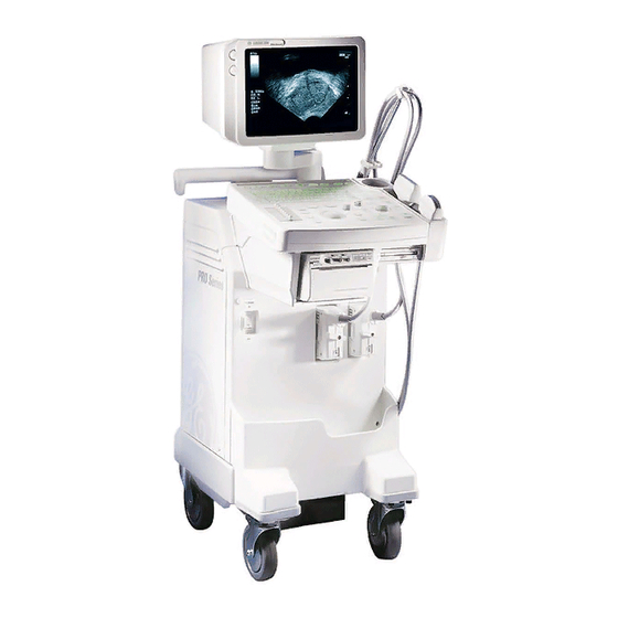
- Page 79 LOGIQ a200 SERVICE MANUAL GE MEDICAL SYSTEMS REV 0 2138853 5–1 INTRODUCTION LOGIQ a200 is a compact ultrasound scanner supporting a wide range of probes. This gives the system added benefits and flexibility to meet diverse applications. LOGIQ a200 SYSTEM 5–2...
- Page 80 LOGIQ a200 SERVICE MANUAL GE MEDICAL SYSTEMS REV 3 2138853 5–3 BLOCK DIAGRAM To Mother board Rear Shutter Control Panel To Mother board Power Foot Switch Supply To Mother board Keyboard B/W Monitor CONN NOVA BUS RTC BUS É É É...
- Page 81 LOGIQ a200 SERVICE MANUAL GE MEDICAL SYSTEMS REV 0 2138853 5–4 WIRING DIAGRAM NFB1 HV ASSY PLUG Core AC OUTLET B/W PRT L(Brown) AC110 V N(Light Blue) G(Green/Yellow) 10A/115V 5A/220V N(Light Blue) POWER SW HV–REF L(Brown) N.C. ISOLATION TRANSFORMER – 15 V...
- Page 82 LOGIQ a200 SERVICE MANUAL GE MEDICAL SYSTEMS REV 0 2138853 5–4 WIRING DIAGRAM (Continued) Brown 115V 115V 100V 100V Brown Brown Brown AC IN AC IN 115V 115V Light Blue 100V 100V Light Blue Light Blue Light Blue Orange 115V...
- Page 83 LOGIQ a200 SERVICE MANUAL GE MEDICAL SYSTEMS REV 0 2138853 5–5 CIRCUIT BOARD DESCRIPTION The following table lists circuit boards and their respective card cage slot assignments on the mother board of the LOGIQ a200 system. TABLE 5– 1 CIRCUIT BOARD DESCRIPTION...
- Page 84 LOGIQ a200 SERVICE MANUAL GE MEDICAL SYSTEMS REV 0 2138853 This page is left blank intentionally. 5–8 DIAGRAMS...
- Page 85 LOGIQ α200 SERVICE MANUAL GE MEDICAL SYSTEMS REV 5 2138853 CHAPTER 6 – RENEWAL PARTS TABLE OF CONTENTS SECTION TITLE PAGE 6–1 RENEWAL PARTS ..............
- Page 86 LOGIQ α200 SERVICE MANUAL GE MEDICAL SYSTEMS REV 5 2138853 TABLE OF CONTENTS (Continued) SECTION TITLE PAGE 6–2–32 Top Cover (FRU No. 409) ........... .
- Page 87 LOGIQ α200 SERVICE MANUAL GE MEDICAL SYSTEMS REV 4 2138853 6–1 RENEWAL PARTS LOGIQ a200 MATERIAL LIST (1/3) PART NAME PART NO. QUANTITY DESCRIPTION OPERATOR CONSOLE ASSY 2157726 220V, NTSC, 4 SWIVEL VER0.3 OPERATOR CONSOLE ASSY 2157727 100V, NTSC, 4 SWIVEL VER0.3...
- Page 88 LOGIQ α200 SERVICE MANUAL GE MEDICAL SYSTEMS REV 4 2138853 6–1 RENEWAL PARTS (continued) LOGIQ α200 MATERIAL LIST (2/3) PART NAME DESCRIPTION PART NO. QUANTITY OPERATOR CONSOLE ASSY 2184999 220V, NTSC, 4 SWIVEL VER1.1 OPERATOR CONSOLE ASSY 2185000 100V, NTSC, 4 SWIVEL VER1.1...
- Page 89 LOGIQ α200 SERVICE MANUAL GE MEDICAL SYSTEMS REV 5 2138853 6–1 RENEWAL PARTS (continued) LOGIQ a200 MATERIAL LIST (3/3) PART NAME QUANTITY DESCRIPTION PART NO. CONSOLE ASSY 2205669 220V, NTSC, 4SW, VER 2.01 CONSOLE ASSY 2224910 220V, NTSC, 4SW, VER 2.01...
- Page 90 LOGIQ α200 SERVICE MANUAL GE MEDICAL SYSTEMS REV 5 2138853 This page is left blank intentionally. 6–6 RENEWAL PARTS...
- Page 91 LOGIQ α200 SERVICE MANUAL GE MEDICAL SYSTEMS REV 4 2138853 OPERATOR CONSOLE ASSY MONITOR BLOCK FRU 100 – 105 See ILLUSTRATION 6–2 KEYBOARD BLOCK (FRU 201 – 204) See ILLUSTRATION 6–3 BODY BLOCK See ILLUSTRATION 6–5 PC BOARDS(2) See ILLUSTRATION 6–4 PC BOARDS(1) See ILLUSTRATION 6–4...
- Page 92 LOGIQ α200 SERVICE MANUAL GE MEDICAL SYSTEMS REV 4 2138853 OPERATOR CONSOLE ASSY 1/7 ILLUSTRATION 6–2 6–8 RENEWAL PARTS...
- Page 93 LOGIQ α200 SERVICE MANUAL GE MEDICAL SYSTEMS REV 5 2138853 LOGIQ a200 2157726, 2157727, 2157728, 2157729, 2157858, 2157730, 2157731, 2157732 2184999, 2185000, 2185001, 2185002, 2183920, 2184519, 2184520, 2184521 2205669, 2205670, 2205671, 2205672, 2205674, 2205675, 2205676, 2205677 MATERIAL LIST (1/7) SECTION FOR...
- Page 94 LOGIQ α200 SERVICE MANUAL GE MEDICAL SYSTEMS REV 5 2138853 OPERATOR CONSOLE ASSY 2/7 206, 209 PG Rivet ILLUSTRATION 6–3 6–10 RENEWAL PARTS...
- Page 95 LOGIQ α200 SERVICE MANUAL GE MEDICAL SYSTEMS REV 5 2138853 LOGIQ a200 2157726, 2157727, 2157728, 2157729, 2157858, 2157730, 2157731, 2157732 2184999, 2185000, 2185001, 2185002, 2183920, 2184519, 2184520, 2184521 2205669, 2205670, 2205671, 2205672, 2205674, 2205675, 2205676, 2205677 MATERIAL LIST (2/7) SECTIO...
- Page 96 LOGIQ α200 SERVICE MANUAL GE MEDICAL SYSTEMS REV 4 2138853 OPERATOR CONSOLE ASSY 3/7 301–304 ILLUSTRATION 6–4 6–12 RENEWAL PARTS...
- Page 97 LOGIQ α200 SERVICE MANUAL GE MEDICAL SYSTEMS REV 8 2138853 LOGIQ α200 2157726, 2157727, 2157728, 2157729, 2157858, 2157730, 2157731, 2157732 2184999, 2185000, 2185001, 2185002, 2183920, 2184519, 2184520, 2184521 2205669, 2205670, 2205671, 2205672, 2205674, 2205675, 2205676, 2205677 MATERIAL LIST (3/7) SECTION...
- Page 98 LOGIQ α200 SERVICE MANUAL GE MEDICAL SYSTEMS REV 4 2138853 OPERATOR CONSOLE ASSY 4/7 ILLUSTRATION 6–5 6–14 RENEWAL PARTS...
- Page 99 LOGIQ α200 SERVICE MANUAL GE MEDICAL SYSTEMS REV 5 2138853 LOGIQ a200 2157726, 2157727, 2157728, 2157729, 2157858, 2157730, 2157731, 2157732 2184999, 2185000, 2185001, 2185002, 2183920, 2184519, 2184520, 2184521 2205669, 2205670, 2205671, 2205672, 2205674, 2205675, 2205676, 2205677 MATERIAL LIST (4/7) SECTION FOR...
- Page 100 LOGIQ α200 SERVICE MANUAL GE MEDICAL SYSTEMS REV 5 2138853 LOGIQ a200 2157726, 2157727, 2157728, 2157729, 2157858, 2157730, 2157731, 2157732 2184999, 2185000, 2185001, 2185002, 2183920, 2184519, 2184520, 2184521 2205669, 2205670, 2205671, 2205672, 2205674, 2205675, 2205676, 2205677 MATERIAL LIST (4/7)(Continued) SECTION FOR...
- Page 101 LOGIQ α200 SERVICE MANUAL GE MEDICAL SYSTEMS REV 4 2138853 This page is left blank intentionally. 6–17 RENEWAL PARTS...
- Page 102 LOGIQ α200 SERVICE MANUAL GE MEDICAL SYSTEMS REV 4 2138853 OPERATOR CONSOLE ASSY 5/7 É É É É É É É É É É É É É É É É É É ILLUSTRATION 6–6 6–18 RENEWAL PARTS...
- Page 103 LOGIQ α200 SERVICE MANUAL GE MEDICAL SYSTEMS REV 5 2138853 LOGIQ a200 2157726, 2157727, 2157728, 2157729, 2157858, 2157730, 2157731, 2157732 2184999, 2185000, 2185001, 2185002, 2183920, 2184519, 2184520, 2184521 2205669, 2205670, 2205671, 2205672, 2205674, 2205675, 2205676, 2205677 MATERIAL LIST (5/7) SECTION FOR...
- Page 104 LOGIQ α200 SERVICE MANUAL GE MEDICAL SYSTEMS REV 7 2138853 LOGIQ a200 2157726, 2157727, 2157728, 2157729, 2157858, 2157730, 2157731, 2157732 2184999, 2185000, 2185001, 2185002, 2183920, 2184519, 2184520, 2184521 2205669, 2205670, 2205671, 2205672, 2205674, 2205675, 2205676, 2205677 MATERIAL LIST (6/7) SECTION FOR...
- Page 105 LOGIQ α200 SERVICE MANUAL GE MEDICAL SYSTEMS REV 4 2138853 LOGIQ a200 2157726, 2157727, 2157728, 2157729, 2157858, 2157730, 2157731, 2157732 2184999, 2185000, 2185001, 2185002, 2183920, 2184519, 2184520, 2184521 2205669, 2205670, 2205671, 2205672, 2205674, 2205675, 2205676, 2205677 MATERIAL LIST (7/7) SECTION FOR...
- Page 106 LOGIQ α200 SERVICE MANUAL GE MEDICAL SYSTEMS REV 4 2138853 This page is left blank intentionally. 6–22 RENEWAL PARTS...
-
Page 107: Renewal Parts
LOGIQ α200 SERVICE MANUAL GE MEDICAL SYSTEMS REV 4 2138853 6–2 DISASSEMBLY/RE-ASSEMBLY WARNING! ONLY QUALIFIED SERVICE PERSONNEL SHOULD REMOVE ANY COVERS OR PANELS. ELECTRICAL HAZARDS EXISTS AT SEVERAL POINTS INSIDE. BECOME THOROUGHLY FAMILIAR WITH ALL HAZARDOUS VOLTAGES AND HIGH CURRENT LEVELS TO AVOID... - Page 108 LOGIQ α200 SERVICE MANUAL GE MEDICAL SYSTEMS REV 4 2138853 6–2–1 Monitor Assy (FRU No. 100) Time Required 5 Minutes Tool Required Screwdriver Procedure WARNING! PERSONAL INJURY HAZARD. VIDEO MONITOR SUPPORT ARM IS SPRING LOADED. RELEASING ARM WHEN MONITOR IS NOT INSTALLED WILL CAUSE SUDDEN UPWARD MOVEMENT.
-
Page 109: Monitor Assy (Fru No. 100)
LOGIQ α200 SERVICE MANUAL GE MEDICAL SYSTEMS REV 4 2138853 6–2–1 Monitor Assy (FRU No. 100) (Continued) 100 Monitor Assy É É É É É É É É É connector É É É É É É É É É MONITOR ASSY DISASSEMBLY ILLUSTRATION 6–7... -
Page 110: Pot Set Assy (Fru No. 101)
LOGIQ α200 SERVICE MANUAL GE MEDICAL SYSTEMS REV 4 2138853 6–2–2 Pot Set Assy (FRU No. 101) Time Required 6 Minute Tool Required Screwdriver Soldering Iron Procedure Refer to ILLUSTRATION 6–8. Turn OFF the system. Remove the Monitor Cover Set. Refer to 6–2–4. -
Page 111: Crt Filter(Fru No. 102)
LOGIQ α200 SERVICE MANUAL GE MEDICAL SYSTEMS REV 4 2138853 6–2–3 CRT Filter(FRU No. 102) Time Required 2 Minutes Tool Required Not necessary Procedure Refer to ILLUSTRATION 6–9. Turn OFF the system. Push the two Filter Clamp Assy inward (1) as shown in ILLUSTRATION 6–9 and remove Filter Clamp Assy. -
Page 112: Monitor Cover Set (Fru No. 103)
LOGIQ α200 SERVICE MANUAL GE MEDICAL SYSTEMS REV 4 2138853 6–2–4 Monitor Cover Set (FRU No. 103) Time Required 4 Minutes Tool Required Screwdriver Procedure Refer to ILLUSTRATION 6–10. Turn OFF the system. Lift and set the Monitor to the highest position by pushing down the Up/down Release Button located on the Swing Arm Assy. -
Page 113: Tilt Assy(Fru No. 104)
LOGIQ α200 SERVICE MANUAL GE MEDICAL SYSTEMS REV 4 2138853 6–2–5 Tilt Assy(FRU No. 104) Time Required 8 Minutes Tool Required Screwdriver Procedure Refer to ILLUSTRATION 6–11. Turn OFF the system. Remove the Monitor Assy (FRU No. 100) from the Swing Arm Assy. Refer to 6–2–1. -
Page 114: Monitor Space Plate (Fru No. 105)
LOGIQ α200 SERVICE MANUAL GE MEDICAL SYSTEMS REV 4 2138853 6–2–6 Monitor Space Plate (FRU No. 105) Time Required 6 Minutes Tool Required Screwdriver Procedure Refer to ILLUSTRATION 6–12. Turn OFF the system. Remove the Monitor Assy (FRU No. 100) from the Swing Arm Assy. Refer to 6–2–1. -
Page 115: Probe Holder (Fru No. 201)
LOGIQ α200 SERVICE MANUAL GE MEDICAL SYSTEMS REV 4 2138853 6–2–7 Probe Holder (FRU No. 201) Time Required 2 Minutes Tool Required Not necessary Procedure Refer to ILLUSTRATION 6–13. Turn OFF the system. Pull the PG latch located at bottom of the Probe Holder. -
Page 116: Holder Bracket Assy (Fru No. 202)
LOGIQ α200 SERVICE MANUAL GE MEDICAL SYSTEMS REV 4 2138853 6–2–8 Holder Bracket Assy (FRU No. 202) Time Required 3 Minutes Tool Required Screwdriver Procedure Refer to ILLUSTRATION 6–14. Turn OFF the system. Remove the Probe Holder (FRU No. 201). Refer to 6–2–7. - Page 117 LOGIQ α200 SERVICE MANUAL GE MEDICAL SYSTEMS REV 4 2138853 This page is left blank intentionally. 6–33 RENEWAL PARTS...
- Page 118 LOGIQ α200 SERVICE MANUAL GE MEDICAL SYSTEMS REV 4 2138853 6–2–9 Keyboard Cover Set (FRU No. 203) Time Required 11 Minutes Tool Required Screwdriver Procedure Refer to ILLUSTRATION 6–15. Turn OFF the system. Remove the Probe Holder (FRU No. 201). Refer to 6–2–7.
-
Page 119: Keyboard Cover Set (Fru No. 203)
LOGIQ α200 SERVICE MANUAL GE MEDICAL SYSTEMS REV 4 2138853 6–2–9 Keyboard Cover Set (FRU No. 203) (Continued) Connector Keyboard Cover Set Ground Terminal Keyboard Assy with KB Cover Top Assy (Bottom View) KB Cover Bottom KEYBOARD COVER SET DISASSEMBLY ILLUSTRATION 6–15... - Page 120 LOGIQ α200 SERVICE MANUAL GE MEDICAL SYSTEMS REV 4 2138853 6–2–10 Keyboard Assy (FRU No. 204) Time Required 6 Minutes Tool Required Screwdriver Procedure Refer to ILLUSTRATION 6–16. Turn OFF the system. Unscrew two screws (1 and 2) on the front bottom of Keyboard.
- Page 121 LOGIQ α200 SERVICE MANUAL GE MEDICAL SYSTEMS REV 4 2138853 6–2–10 Keyboard Assy (FRU No. 204)) (Continued) 204 Keyboard Assy Connector Ground Terminals Keyboard Assy with KB Cover Top Assy (Bottom View) KEYBOARD ASSY DISASSEMBLY ILLUSTRATION 6–16 6–37 RENEWAL PARTS...
-
Page 122: Trackball Assy (Fru No. 205)
LOGIQ α200 SERVICE MANUAL GE MEDICAL SYSTEMS REV 4 2138853 6–2–11 Trackball Assy (FRU No. 205) Time Required 8 Minutes Tool Required Screwdriver Procedure Refer to ILLUSTRATION 6–17. Turn OFF the system. Pull the Keyboard Assy out with KB Cover Top Assy. -
Page 123: Tgc Assy (Fru No. 206)
LOGIQ α200 SERVICE MANUAL GE MEDICAL SYSTEMS REV 4 2138853 6–2–12 TGC Assy (FRU No. 206) Time Required 8 Minutes Tool Required Screwdriver Procedure Refer to ILLUSTRATION 6–18. Turn OFF the system. Pull the Keyboard Assy out with KB Cover Top Assy. Refer to 6–2–10. -
Page 124: Encoder Set (Fru No. 207)
LOGIQ α200 SERVICE MANUAL GE MEDICAL SYSTEMS REV 4 2138853 6–2–13 Encoder Set (FRU No. 207) Time Required 14 Minutes Tool Required Screwdriver, Hexagonal Wrench Procedure Refer to ILLUSTRATION 6–19 Turn OFF the system. Pull the Keyboard Assy out with KB Cover Top Assy. Refer to 6–2–10 Unscrew hexagonal screws (1) on each Encoder Knob and remove three knobs. -
Page 125: Freeze/Record Key Assy (Fru No. 208)
LOGIQ α200 SERVICE MANUAL GE MEDICAL SYSTEMS REV 4 2138853 6–2–14 Freeze/Record Key Assy (FRU No. 208) Time Required 10 Minutes Tool Required Screwdriver Procedure Refer to ILLUSTRATION 6–20. Turn OFF the system. Pull the Keyboard Assy out with KB Cover Top Assy. Refer to 6–2–10. -
Page 126: Tgc Knob Set (Fru No. 209)
LOGIQ α200 SERVICE MANUAL GE MEDICAL SYSTEMS REV 4 2138853 6–2–15 TGC Knob Set (FRU No. 209) Time Required 5 Minutes Tool Required None Procedure Refer to ILLUSTRATION 6–21. Turn OFF the system. Pull out the TGC Knobs (1 – 8). -
Page 127: Probe Protector Sheet Set (Fru No. 210)
LOGIQ α200 SERVICE MANUAL GE MEDICAL SYSTEMS REV 5 2138853 6–2–16 Probe Protector Sheet Set (FRU No. 210) Time Required 1 Minutes Tool Required None Procedure Refer to ILLUSTRATION 6–22. Turn OFF the system. Insert the Probe Protector Sheets (1 – 2). -
Page 128: Key Sheet Assy (Fru No. 211)
LOGIQ α200 SERVICE MANUAL GE MEDICAL SYSTEMS REV 5 2138853 6–2–17 Key Sheet Assy (FRU No. 211) Time Required 25 Minutes Tool Required Screw Driver, Hexagonal Wrench, Boxer(5mm). Procedure Refer to ILLUSTRATION 6–23. Turn OFF the system. Remove the Keyboard assy. Refer to 6–2–10. -
Page 129: Key Sheet Assy (Continued) (Fru No. 211)
LOGIQ α200 SERVICE MANUAL GE MEDICAL SYSTEMS REV 5 2138853 6–2–17 Key Sheet Assy (continued) (FRU No. 211) 204. Keyboard Assy CN3 CN4 Track Ball Keyboard Bracket Track Ball 211. KeySheet Assy KEY SHEET ASSY DISASSEMBLY ILLUSTRATION 6–23 6–45 RENEWAL PARTS... -
Page 130: P.c.board(S) (Fru No.301 Through 304)
LOGIQ α200 SERVICE MANUAL GE MEDICAL SYSTEMS REV 5 2138853 6–2–18 P.C.Board(s) (FRU No.301 through 304) Time Required 7 Minutes Tool Required Screwdriver Procedure CAUTION An electrostatic discharge may damage a component. Turn OFF power and wear the wrist strap before you remove a circuit boards. Do not unplug the power cord to keep ground continuity. - Page 131 LOGIQ α200 SERVICE MANUAL GE MEDICAL SYSTEMS REV 5 2138853 6–2–18 P.C.Board(s) (FRU No.301 through 304) (Continued) Bracket Nest Cardcage No. Board P.C.BOARD(S) REMOVAL ILLUSTRATION 6–24 6–47 RENEWAL PARTS...
- Page 132 LOGIQ α200 SERVICE MANUAL GE MEDICAL SYSTEMS REV 5 2138853 6–2–19 HV Assy (FRU No. 305) Time Required 10 Minutes Tool Required Screwdriver Procedure Refer to ILLUSTRATION 6–25. Turn OFF the system. Remove the Left Cover (FRU 404). Refer to 6–2–27.
-
Page 133: Hv Assy (Fru No. 305)
LOGIQ α200 SERVICE MANUAL GE MEDICAL SYSTEMS REV 5 2138853 6–2–19 HV Assy (FRU No. 305) (Continued) 305 HV Assy Transparent Plastic Cover HV ASSY DISASSEMBLY ILLUSTRATION 6–25 6–49 RENEWAL PARTS... -
Page 134: Conn Assy (Fru No. 306)
LOGIQ α200 SERVICE MANUAL GE MEDICAL SYSTEMS REV 5 2138853 6–2–20 CONN Assy (FRU No. 306) Time Required 13 Minutes Tool Required Screwdriver Procedure Refer to ILLUSTRATION 6–26. Turn OFF the system and plug out. Remove the Shield Panel (FRU 307). Refer to 6–2–21. - Page 135 LOGIQ α200 SERVICE MANUAL GE MEDICAL SYSTEMS REV 5 2138853 This page is left blank intentionally. 6–51 RENEWAL PARTS...
- Page 136 LOGIQ α200 SERVICE MANUAL GE MEDICAL SYSTEMS REV 5 2138853 6–2–21 Shield Panel (FRU No. 307) Time Required 11 Minutes Tool Required Screwdriver Procedure CAUTION Do NOT unplug the power cord before OFF the power switch. Refer to ILLUSTRATION 6–27.
-
Page 137: Shield Panel (Fru No. 307)
LOGIQ α200 SERVICE MANUAL GE MEDICAL SYSTEMS REV 5 2138853 6–2–21 Shield Panel (FRU No. 307) (Continued) 307 Shield Panel SHIELD PANEL DISASSEMBLY ILLUSTRATION 6–27 6–53 RENEWAL PARTS... - Page 138 LOGIQ α200 SERVICE MANUAL GE MEDICAL SYSTEMS REV 5 2138853 6–2–22 Mother Assy (FRU No. 308) Time Required 0.5 Hours Tool Required Screwdriver Hexagonal Wrench Procedure CAUTION An electrostatic discharge may damage a component. Turn OFF power and wear the wrist strap before you remove a circuit boards.
-
Page 139: Mother Assy (Fru No. 308)
LOGIQ α200 SERVICE MANUAL GE MEDICAL SYSTEMS REV 5 2138853 6–2–22 Mother Assy (FRU No. 308) (Continued) 308 Mother Assy Bracket Harness NEST MOTHER ASSY DISASSEMBLY ILLUSTRATION 6–28 6–55 RENEWAL PARTS... -
Page 140: Nest Box (Fru No. 309)
LOGIQ α200 SERVICE MANUAL GE MEDICAL SYSTEMS REV 5 2138853 6–2–23 Nest Box (FRU No. 309) Time Required 0.6 Hour Tool Required Screwdriver Hexagonal Wrench CAUTION An electrostatic discharge may damage a component. Turn OFF power and wear the wrist strap before you remove a circuit boards. - Page 141 LOGIQ α200 SERVICE MANUAL GE MEDICAL SYSTEMS REV 5 2138853 6–2–23 Nest Box (FRU No. 309) (Continued) Remove the CONN Assy (FRU 306). Refer to 6–2–20. Remove the Mother Assy (FRU 308). Refer to 6–2–22. Remove the eight Screws (1 – 8) on both side of the Nest Box. Refer to ILLUSTRATION 6–29.
- Page 142 LOGIQ α200 SERVICE MANUAL GE MEDICAL SYSTEMS REV 5 2138853 6–2–24 Swing Arm Assy (FRU No. 401) Time Required 0.6 Hour Tool Required Screwdriver Hex Wrench Procedure Refer to ILLUSTRATION 6–30. Turn OFF the system and unplug the power cord from outlet.
-
Page 143: Swing Arm Assy (Fru No. 401)
LOGIQ α200 SERVICE MANUAL GE MEDICAL SYSTEMS REV 5 2138853 6–2–24 Swing Arm Assy (FRU No. 401) (Continued) 401 Swing Arm Assy NECK ASSY DISASSEMBLY ILLUSTRATION 6–30 6–59 RENEWAL PARTS... - Page 144 LOGIQ α200 SERVICE MANUAL GE MEDICAL SYSTEMS REV 5 2138853 6–2–25 Pipe Assy (FRU No. 402) Time Required 0.4 Hour Tool Required Screwdriver Hex Wrench Procedure Refer to ILLUSTRATION 6–31. Turn OFF the system and unplug the power cord from outlet.
-
Page 145: Pipe Assy (Fru No. 402)
LOGIQ α200 SERVICE MANUAL GE MEDICAL SYSTEMS REV 5 2138853 6–2–25 Pipe Assy (FRU No. 402)) (Continued) 402 Pipe Assy CN02 Two Connectors NECK ASSY DISASSEMBLY ILLUSTRATION 6–31 6–61 RENEWAL PARTS... - Page 146 LOGIQ α200 SERVICE MANUAL GE MEDICAL SYSTEMS REV 5 2138853 6–2–26 Pole Cover (FRU No. 403) Time Required 20 Minutes Tool Required Screwdriver Procedure Refer to ILLUSTRATION 6–32. Turn OFF the system. Remove the Monitor Assy (FRU No. 100) from the Swing Arm Assy. Refer to 6–2–1.
-
Page 147: Pole Cover (Fru No. 403)
LOGIQ α200 SERVICE MANUAL GE MEDICAL SYSTEMS REV 5 2138853 6–2–26 Pole Cover (FRU No. 403)) (Continued) 403 Pole Cover POLE COVER DISASSEMBLY ILLUSTRATION 6–32 6–63 RENEWAL PARTS... -
Page 148: Left Cover (Fru No. 404)
LOGIQ α200 SERVICE MANUAL GE MEDICAL SYSTEMS REV 5 2138853 6–2–27 Left Cover (FRU No. 404) Time Required 5 Minutes Tool Required Screwdriver Procedure Refer to ILLUSTRATION 6–33. Turn OFF the system. Remove four screw caps and unscrew four screws (1 – 4). -
Page 149: Right Cover (Fru No. 405)
LOGIQ α200 SERVICE MANUAL GE MEDICAL SYSTEMS REV 5 2138853 6–2–28 Right Cover (FRU No. 405) Time Required 5 Minutes Tool Required Screwdriver Procedure Refer to ILLUSTRATION 6–34. Turn OFF the system. Remove the four screw caps and unscrew four screws (1 – 4). -
Page 150: Front Base Cover (Fru No. 406)
LOGIQ α200 SERVICE MANUAL GE MEDICAL SYSTEMS REV 5 2138853 6–2–29 Front Base Cover (FRU No. 406) Time Required 5 Minutes Tool Required Screwdriver Procedure Refer to ILLUSTRATION 6–35. Turn OFF the system. Remove the Left Cover (FRU 404). Refer to 6–2–27. - Page 151 LOGIQ α200 SERVICE MANUAL GE MEDICAL SYSTEMS REV 5 2138853 This page is left blank intentionally. 6–67 RENEWAL PARTS...
- Page 152 LOGIQ α200 SERVICE MANUAL GE MEDICAL SYSTEMS REV 5 2138853 6–2–30 Front Cover (FRU No. 407) Time Required 5 Minutes Tool Required Screwdriver Procedure Refer to ILLUSTRATION 6–36. Turn OFF the system. Remove the Left Cover (FRU 404). Refer to 6–2–27.
-
Page 153: Front Cover (Fru No. 407)
LOGIQ α200 SERVICE MANUAL GE MEDICAL SYSTEMS REV 5 2138853 6–2–30 Front Cover (FRU No. 407) (Continued) 407 Front Cover FRONT COVER DISASSEMBLY ILLUSTRATION 6–36 6–69 RENEWAL PARTS... -
Page 154: Rear Cover (Fru No. 408)
LOGIQ α200 SERVICE MANUAL GE MEDICAL SYSTEMS REV 5 2138853 6–2–31 Rear Cover (FRU No. 408) Time Required 5 Minutes Tool Required Screwdriver Procedure Refer to ILLUSTRATION 6–37. Turn OFF the system. Remove the Left Cover (FRU 404). Refer to 6–2–27. - Page 155 LOGIQ α200 SERVICE MANUAL GE MEDICAL SYSTEMS REV 5 2138853 This page is left blank intentionally. 6–71 RENEWAL PARTS...
-
Page 156: Top Cover (Fru No. 409)
LOGIQ α200 SERVICE MANUAL GE MEDICAL SYSTEMS REV 5 2138853 6–2–32 Top Cover (FRU No. 409) Time Required 5 Minutes Tool Required Screwdriver Procedure Refer to ILLUSTRATION 6–38. Turn OFF the system. Remove the Left Cover (FRU 404). Refer to 6–2–27. - Page 157 LOGIQ α200 SERVICE MANUAL GE MEDICAL SYSTEMS REV 5 2138853 6–2–32 Top Cover (FRU No. 409) (Continued) 409 Top Cover É É É É É É É É É É É É É É É É É É REAR COVER DISASSEMBLY ILLUSTRATION 6–38...
-
Page 158: Printer Cover (Fru No. 410)
LOGIQ α200 SERVICE MANUAL GE MEDICAL SYSTEMS REV 5 2138853 6–2–33 Printer Cover (FRU No. 410) Time Required 5 Minutes Tool Required Screwdriver Procedure Refer to ILLUSTRATION 6–39. Turn OFF the system. Remove the Front Cover (FRU 407). Refer to 6–2–30. - Page 159 LOGIQ α200 SERVICE MANUAL GE MEDICAL SYSTEMS REV 5 2138853 This page is left blank intentionally. 6–75 RENEWAL PARTS...
-
Page 160: Printer Bracket Assy(Fru No. 411), Back Bracket Assy (Fru No. 412)
LOGIQ α200 SERVICE MANUAL GE MEDICAL SYSTEMS REV 5 2138853 6–2–34 Printer Bracket Assy(FRU No. 411), Back Bracket Assy (FRU No. 412) Time Required 30 Minutes Tool Required Screwdriver Hexagonal Wrench Procedure Refer to ILLUSTRATION 6–40. Turn OFF the system. - Page 161 LOGIQ α200 SERVICE MANUAL GE MEDICAL SYSTEMS REV 5 2138853 6–2–34 Printer Bracket Assy(FRU No. 411), Back Bracket Assy (FRU No. 412) (Continued) 412 Back Bracket Assy 411 Printer Bracket Assy PRINTER BRACKET ASSY AND BACK BRACKET ASSY DISASSEMBLY ILLUSTRATION 6–40 6–77...
-
Page 162: Rear Handle (Fru No. 413)
LOGIQ α200 SERVICE MANUAL GE MEDICAL SYSTEMS REV 5 2138853 6–2–35 Rear Handle (FRU No. 413) Time Required 1 Hours Tool Required Screwdriver Hexagonal Wrench Procedure Refer to ILLUSTRATION 6–41. Turn OFF the system. Remove the Keyboard Assy (FRU 204). Refer to 6–2–10. - Page 163 LOGIQ α200 SERVICE MANUAL GE MEDICAL SYSTEMS REV 5 2138853 6–2–35 Rear Handle (FRU No. 413) (Continued) É É É É É É É É É É É É 413 Rear Handle REAR HANDLE DISASSEMBLY ILLUSTRATION 6–41 6–79 RENEWAL PARTS...
- Page 164 LOGIQ α200 SERVICE MANUAL GE MEDICAL SYSTEMS REV 5 2138853 6–2–36 Neck Frame (FRU No. 414) Time Required 0.5 Hours Tool Required Screwdriver Hexagonal Wrench Procedure Refer to ILLUSTRATION 6–42. Turn OFF the system. Remove the Keyboard Assy (FRU No. 204). Refer to 6–2–10.
-
Page 165: Neck Frame (Fru No. 414)
LOGIQ α200 SERVICE MANUAL GE MEDICAL SYSTEMS REV 5 2138853 6–2–36 Neck Frame (FRU No. 414) (Continued) 414 Neck Frame NECK FRAME DISASSEMBLY ILLUSTRATION 6–42 6–81 RENEWAL PARTS... -
Page 166: Rear Panel Assy (Fru No. 415)
LOGIQ α200 SERVICE MANUAL GE MEDICAL SYSTEMS REV 5 2138853 6–2–37 Rear Panel Assy (FRU No. 415) Time Required 0.5 Hour Tool Required Screwdriver Procedure Refer to ILLUSTRATION 6–43. Turn OFF the system. Remove the Left Cover (FRU 404). Refer to 6–2–27. - Page 167 LOGIQ α200 SERVICE MANUAL GE MEDICAL SYSTEMS REV 5 2138853 6–2–37 Rear Panel Assy (FRU No. 415) (Continued) É É É É É É É É É É É É 415 Rear Panel Assy REAR PANEL ASSY DISASSEMBLY ILLUSTRATION 6–43 6–83...
- Page 168 LOGIQ α200 SERVICE MANUAL GE MEDICAL SYSTEMS REV 5 2138853 6–2–38 Power S/W Assy (FRU No. 416) Time Required 10 Minutes Tool Required Screwdriver Procedure CAUTION Do NOT unplug the power cord before OFF the power switch. Refer to ILLUSTRATION 6–44.
-
Page 169: Power S/W Assy (Fru No. 416)
LOGIQ α200 SERVICE MANUAL GE MEDICAL SYSTEMS REV 5 2138853 6–2–38 Power S/W Assy (FRU No. 416) (Continued) 416 Power S/W Assy POWER S/W ASSY DISASSEMBLY ILLUSTRATION 6–44 6–85 RENEWAL PARTS... -
Page 170: Ac Fan Assy (Fru No. 417)
LOGIQ α200 SERVICE MANUAL GE MEDICAL SYSTEMS REV 5 2138853 6–2–39 AC Fan Assy (FRU No. 417) Time Required 45 Minutes Tool Required Screwdriver Procedure Refer to ILLUSTRATION 6–45. Turn OFF the system. Remove the Left Cover (FRU 404). Refer to 6–2–27. - Page 171 LOGIQ α200 SERVICE MANUAL GE MEDICAL SYSTEMS REV 5 2138853 6–2–39 AC Fan Assy (FRU No. 417) (Continued) 417 AC Fan Assy CN01 É É É É É É É É É É É É É É É É É É...
-
Page 172: Front Caster (Fru No. 418)
LOGIQ α200 SERVICE MANUAL GE MEDICAL SYSTEMS REV 5 2138853 6–2–40 Front Caster (FRU No. 418) Time Required 15 Minutes Tool Required Hexagonal Wrench Procedure Refer to ILLUSTRATION 6–46. Turn OFF the system. Put a box below the Power Trans box. -
Page 173: Rear Caster (Fru No. 419)
LOGIQ α200 SERVICE MANUAL GE MEDICAL SYSTEMS REV 5 2138853 6–2–41 Rear Caster (FRU No. 419) Time Required 15 Minutes Tool Required Hexagonal Wrench Procedure Refer to ILLUSTRATION 6–47. Turn OFF the system. Put a box below the Power Trans box. -
Page 174: Bumper Set (Fru No. 420)
LOGIQ α200 SERVICE MANUAL GE MEDICAL SYSTEMS REV 5 2138853 6–2–42 Bumper Set (FRU No. 420) Time Required 10 Minutes Tool Required Screwdriver Hexagonal Wrench Procedure Refer to ILLUSTRATION 6–48. Turn OFF the system. Remove the Left Cover (FRU 404). Refer to 6–2–27. -
Page 175: Emi Cover L (Fru No. 421)
LOGIQ α200 SERVICE MANUAL GE MEDICAL SYSTEMS REV 5 2138853 6–2–43 EMI Cover L (FRU No. 421) Time Required 5 Minutes Tool Required Screwdriver Procedure Refer to ILLUSTRATION 6–49. Turn OFF the system. Remove the Left Cover (FRU 404). Refer to 6–2–27. -
Page 176: Pcb Guide Assy (Fru No. 422)
LOGIQ α200 SERVICE MANUAL GE MEDICAL SYSTEMS REV 5 2138853 6–2–44 PCB Guide Assy (FRU No. 422) Time Required 5 Minutes Tool Required Screwdriver Procedure Refer to ILLUSTRATION 6–34. Turn OFF the system. Remove the Right Cover(FRU 405). Refer to 6–2–28. - Page 177 LOGIQ α200 SERVICE MANUAL GE MEDICAL SYSTEMS REV 5 2138853 This page is left blank intentionally. 6–93 RENEWAL PARTS...
-
Page 178: Terminal Block 12 Assy (Fru No. 501)
LOGIQ α200 SERVICE MANUAL GE MEDICAL SYSTEMS REV 5 2138853 6–2–45 Terminal Block 12 Assy (FRU No. 501) Time Required 10 Minutes Tool Required Screwdriver Hexagonal Wrench Procedure CAUTION Do NOT unplug the power cord before OFF the power switch. - Page 179 LOGIQ α200 SERVICE MANUAL GE MEDICAL SYSTEMS REV 5 2138853 6–2–45 Terminal Block 12 Assy (FRU No. 501) (Continued) É É É 501 Terminal Block 12 Assy É É É É É É É É É É É É É É É...
-
Page 180: Terminal Block 6 Assy (Fru No. 502)
LOGIQ α200 SERVICE MANUAL GE MEDICAL SYSTEMS REV 5 2138853 6–2–46 Terminal Block 6 Assy (FRU No. 502) Time Required 10 Minutes Tool Required Screwdriver Procedure CAUTION Do NOT unplug the power cord before OFF the power switch. Refer to ILLUSTRATION 6–52. - Page 181 LOGIQ α200 SERVICE MANUAL GE MEDICAL SYSTEMS REV 5 2138853 6–2–46 Terminal Block 6 Assy (FRU No. 502) (Continued) É É É 502 Terminal Block 6 Assy É É É É É É É É É É É É É É É...
-
Page 182: Smps Assy (Fru No. 503)
LOGIQ α200 SERVICE MANUAL GE MEDICAL SYSTEMS REV 5 2138853 6–2–47 SMPS Assy (FRU No. 503) Time Required 10 Minutes Tool Required Screwdriver Hexagonal Wrench (Key Size: 4 mm) Procedure Refer to 6–4, SMPS Assy REPLACEMENT. 6–98 RENEWAL PARTS... - Page 183 LOGIQ α200 SERVICE MANUAL GE MEDICAL SYSTEMS REV 5 2138853 This page is left blank intentionally. 6–99 RENEWAL PARTS...
-
Page 184: Power Trans Assy (Fru No. 504)
LOGIQ α200 SERVICE MANUAL GE MEDICAL SYSTEMS REV 5 2138853 6–2–48 Power Trans Assy (FRU No. 504) Time Required 20 Minutes Tool Required Screwdriver Hexagonal Wrench Procedure CAUTION Do NOT unplug the power cord before OFF the power switch. Refer to ILLUSTRATION 6–53. - Page 185 LOGIQ α200 SERVICE MANUAL GE MEDICAL SYSTEMS REV 5 2138853 6–2–48 Power Trans Assy (FRU No. 504) (Continued) É É É É É É É É É É É É É É É É É É É É É É É É...
-
Page 186: Circuit Breaker Set (Fru No. 505)
LOGIQ α200 SERVICE MANUAL GE MEDICAL SYSTEMS REV 5 2138853 6–2–49 Circuit Breaker Set (FRU No. 505) Time Required 30 Minutes Tool Required Screwdriver Procedure CAUTION Do NOT unplug the power cord before OFF the power switch. Refer to ILLUSTRATION 6–54. -
Page 187: Fuse Replacement
LOGIQ α200 SERVICE MANUAL GE MEDICAL SYSTEMS REV 5 2138853 6–3 FUSE REPLACEMENT 6–3–1 Introduction LOGIQ α200 has three replaceable fuses. The table below states the items of those fuses. TABLE 6– 1 REPLACEABLE FUSES LOCATION Ref. No. RATING REMARKS... - Page 188 LOGIQ α200 SERVICE MANUAL GE MEDICAL SYSTEMS REV 5 2138853 6–3–2 Replacement Procedures (Continued) (A) F1 and F2 on HV Assy CAUTION Make sure that only fuse with the required rated current and of the same type is used for replacement.
- Page 189 LOGIQ α200 SERVICE MANUAL GE MEDICAL SYSTEMS REV 5 2138853 6–3–2 Replacement Procedures (Continued) (B) F1 on Monitor Assy 1. Turn the system power OFF. Follow the OSHA Lockout/Tagout Requirements (29 CFR 1910.147, Direction 46–015902). Remove the Monitor Bottom Cover and Monitor Rear Cover. Refer to 6–2–4.
-
Page 190: Smps Assy Replacement
LOGIQ α200 SERVICE MANUAL GE MEDICAL SYSTEMS REV 5 2138853 6–4 SMPS Assy REPLACEMENT 6–4–1 Introduction This section describes the procedures for replacing the SMPS Assy unit of LOGIQ α200. 6–4–2 Replacement Procedure READ and UNDERSTAND these instructions thoroughly before proceeding with the replacement. Perform each step in sequence and check it off when completed. - Page 191 LOGIQ α200 SERVICE MANUAL GE MEDICAL SYSTEMS REV 5 2138853 6–4–2 Replacement Procedure (Continued) (B) Disconnecting Cables Disconnect seven cables listed below. Cut the tie wraps off if necessary. For each cable, refer to ILLUSTRATION 6–57. a. Disconnect six connectors (J10 – J13, J28, and J29) from the Mother Assy.
- Page 192 LOGIQ α200 SERVICE MANUAL GE MEDICAL SYSTEMS REV 5 2138853 6–4–2 Replacement Procedure (Continued) (C) Replacing SMPS Assy Unscrew two hexagonal bolts (1 and 2). Two bolts are located at the front of SMPS Assy. Pull out the SMPS Assy forewards. Refer to ILLUSTRATION 6–58.
- Page 193 LOGIQ α200 SERVICE MANUAL GE MEDICAL SYSTEMS REV 5 2138853 6–4–2 Replacement Procedure (Continued) (D) Final Procedure Connect four cables with the appropriate connectors. For the details of cables, refer to 6–4–2, (B), Disconnecting Cables. Re–assemble the removal parts. Plug the system and power it ON.
- Page 194 LOGIQ α200 SERVICE MANUAL GE MEDICAL SYSTEMS REV 5 2138853 This page is left blank intentionally. 6–110 RENEWAL PARTS...
- Page 195 LOGIQ a200 SERVICE MANUAL GE MEDICAL SYSTEMS REV 3 2138853 CHAPTER 7 – PERIODIC MAINTENANCE TABLE OF CONTENTS SECTION TITLE PAGE 7–1 INTRODUCTION ..............
-
Page 196: Periodic Maintenance
LOGIQ a200 SERVICE MANUAL GE MEDICAL SYSTEMS REV 0 2138853 This page is left blank intentionally. 7–2 PERIODIC MAINTENANCE... -
Page 197: Periodic Maintenance Procedure
LOGIQ a200 SERVICE MANUAL GE MEDICAL SYSTEMS REV 0 2138853 7–1 INTRODUCTION This chapter provides Periodic Maintenance procedures. It is an effective and efficient method of reducing equipment down time and service cost. 7–1–1 Periodic Maintenance Periodic Maintenance consists of visual inspections, system performance checks, and periodic cleaning of certain critical parts. -
Page 198: Cleaning
LOGIQ a200 SERVICE MANUAL GE MEDICAL SYSTEMS REV 2 2138853 7–2–2 Cleaning Clean CRT filter. Clean the Fans by using a vacuum cleaner and bristled brush. Clean out the interior of the Console by using a vacuum cleaner. 7–2–3 Measurement Make sure that electrical outlet of hospital should provide the power line standard. -
Page 199: Note
LOGIQ a200 SERVICE MANUAL GE MEDICAL SYSTEMS REV 3 2138853 7–3 ELECTRICAL SAFETY TESTS The following tests are performed at the factory and should be performed at the site. These tests are: grounding continuity, chassis leakage current, probe leakage current, and ECG leakage current. All measurements are made with an Electrical Safety Analyzer Model Dale 600/600E built by Dale Technology Corporation or equivalent device. -
Page 200: Grounding Continuity
LOGIQ a200 SERVICE MANUAL GE MEDICAL SYSTEMS REV 3 2138853 7–3–2 Grounding Continuity CAUTION Electric Shock Hazard. The patient must not be contacted to the equipment during this test. Measure the resistance from the third pin of the attachment plug to the exposed metal parts of the case (ILLUSTRATION 7–2). -
Page 201: Chassis Leakage Current Test
LOGIQ a200 SERVICE MANUAL GE MEDICAL SYSTEMS REV 3 2138853 7–3–3 Chassis Leakage Current Test Definition Leakage current is the electrical current that could flow ground wire break. The unit, the probes, the ECG module, and all external peripherals must be tested. - Page 202 LOGIQ a200 SERVICE MANUAL GE MEDICAL SYSTEMS REV 3 2138853 7–3–3 Chassis Leakage Current Test (Continued) Meter Procedure Follow these steps to test the unit for leakage current. Turn the LOGIQ a200 unit OFF. Plug the unit into the meter, and the meter into the tested AC wall outlet (Refer to ILLUSTRATION 7–4).
- Page 203 LOGIQ a200 SERVICE MANUAL GE MEDICAL SYSTEMS REV 3 2138853 7–3–3 Chassis Leakage Current Test (Continued) Data Sheet for Chassis Source Leakage Current Follow the foregoing test procedure. The test passes when all readings measure less than the value shown in the table below (TABLE 7–...
-
Page 204: Probe Leakage Current Test
LOGIQ a200 SERVICE MANUAL GE MEDICAL SYSTEMS REV 3 2138853 7–3–4 Probe Leakage Current Test Definition This test measures the current that would flow to ground from any of the probes through a patient who is being scanned and becomes grounded by touching some other grounded surface. - Page 205 LOGIQ a200 SERVICE MANUAL GE MEDICAL SYSTEMS REV 3 2138853 7–3–4 Probe Leakage Current Test (Continued) Meter Procedure Using Probe Adapter The Dale 600/600E provides a method for testing probes independently from the system. The meter utilizes a probe adapter to apply a test potential commonly to all connector pins.
- Page 206 LOGIQ a200 SERVICE MANUAL GE MEDICAL SYSTEMS REV 3 2138853 7–3–4 Probe Leakage Current Test (Continued) Plug the probe adapter into the meter’s connector marked ”EXTERNAL” (Refer to ILLUSTRATION 7–6 ). Set the meter’s ”FUNCTION” switch to EXTERNAL position. Add the saline probe and the imaging area of the probe into the saline bath.
- Page 207 LOGIQ a200 SERVICE MANUAL GE MEDICAL SYSTEMS REV 3 2138853 7–3–4 Probe Leakage Current Test (Continued) Data Sheet for Transducer Source Leakage Current Follow the foregoing test procedure for every transducer. The test passes when all readings measure less than the value shown in the table below (TABLE 7–...
-
Page 208: When There's Too Much Leakage Current
LOGIQ a200 SERVICE MANUAL GE MEDICAL SYSTEMS REV 3 2138853 7–3–5 When There’s Too Much Leakage Current... Chassis Fails Check the ground on the power cord and plug for continuity. Ensure the ground is not broken, frayed, or intermittent. Replace any defective part. - Page 209 LOGIQ a 200 SERVICE MANUAL GE MEDICAL SYSTEMS REV 0 2138853 CHAPTER 8 – INSTALLATION FOR OPTIONS TABLE OF CONTENTS SECTION TITLE PAGE 8–1 INTRODUCTION ..............
- Page 210 LOGIQ a 200 SERVICE MANUAL GE MEDICAL SYSTEMS REV 0 2138853 This page is left blank intentionally. 8–2 INSTALLATION FOR OPTIONS...
- Page 211 LOGIQ a 200 SERVICE MANUAL GE MEDICAL SYSTEMS REV 0 2138853 8–1 INTRODUCTION This chapter is provided to keep option installation instructions. Place all option installation instructions in this chapter after completing the installation of the options. 8–3 INSTALLATION FOR OPTIONS...
- Page 212 LOGIQ a 200 SERVICE MANUAL GE MEDICAL SYSTEMS REV 0 2138853 This page is left blank intentionally. 8–4 INSTALLATION FOR OPTIONS...
Need help?
Do you have a question about the LOGIQ ?200 and is the answer not in the manual?
Questions and answers