ELTEX ESR-100 Operation Manual
Esr series
Hide thumbs
Also See for ESR-100:
- Quick start and installation manual (19 pages) ,
- User manual (650 pages) ,
- User manual (575 pages)

Related Manuals for ELTEX ESR-100


Summary of Contents for ELTEX ESR-100
- Page 1 ESR Series Routers ESR-100, ESR-200, ESR-1000, ESR-1200 Operation Manual, Firmware Ver. 1.2.0...
- Page 2 - 7.15 PBR routing policy configuration - 7.19 Configuring remote access to corporate network via PPTP protocol Version 1.5 06/08/2015 Added description for ESR-100, ESR-200 Added chapters: - 2.4.2 ESR-100, ESR-200 design Edited chapters: - 2.4 Design - 2.5 Delivery package - 3 Installation and connection - 7.1 VLAN configuration...
- Page 3 - 6.6 Bridge configuration - 6.7 RIP configuration - 6.8 OSPF configuration - 6.9 BGP configuration - 6.10 GRE tunnel configuration - 6.11 L2TPv3 tunnel configuration - 6.12 Route-based IPsec VPN configuration - 6.13 Configuring remote access to corporate network via PPTP protocol - 6.14 Configuring remote access to corporate network via L2TP/IPsec protocol...
-
Page 4: Table Of Contents
2.2.7 Network security functions ..................... 11 2.3 Main specifications ........................... 11 2.4 Design ............................... 13 2.4.1 ESR-1000, ESR-1200 design ..................... 13 2.4.2 ESR-100, ESR-200 design ......................16 2.4.3 Light Indication ........................18 2.5 Delivery Package ..........................20 3 INSTALLATION AND CONNECTION ......................22 3.1 Support brackets mounting ...................... - Page 5 7.16 PBR routing policy configuration ....................... 63 7.16.1 Route-map for BGP configuration ..................63 7.16.2 Route-map based on access control lists (Policy-based routing) ......... 65 7.17 GRE tunnel configuration ........................67 7.18 L2TPv3 tunnel configuration ......................69 7.19 IPsec VPN configuration ........................71 7.19.1 Route-based IPsec VPN configuration: .................
-
Page 6: Introduction
INTRODUCTION Abstract Today, large-scale communication network development projects are becoming increasingly common. One of the main tasks in implementation of large multiservice networks is the creation of reliable high-performance transport network that will serve as a backbone in multilayer architecture of next-generation networks. -
Page 7: Product Description
PRODUCT DESCRIPTION Purpose ESR series devices are the high performance multi-purpose network routers. Device combines traditional network features with a complex multi-tier approach to routing security, and ensures robust corporate environment protection. Device has a built-in firewall that enables protection of your network environment and supports latest data security, encryption, authentication and anti-intrusion features. -
Page 8: Functions For Mac Address Processing
2.2.2 Functions for MAC address processing Table 2.2 lists MAC address processing functions of the device Table 2.2 —MAC address processing functions MAC address MAC address table sets the correspondence between MAC addresses and device table interfaces and is used for data packet routing. Routers support table capacity up to 16K of MAC addresses and reserve specific MAC addresses for the system use. -
Page 9: Third-Layer Functions Of Osi Model
2.2.4 Third-layer functions of OSI model Table 2.4 lists third-layer functions (OSI Layer 3). Table 2.4 —Third-layer functions description (OSI Layer 3) Administrator of the router can add or remove static records into/from the routing Static IP routes table. Dynamic routing With dynamic routing protocols, the device will be able to exchange the routing information with neighbouring routers and automatically create a routing table. -
Page 10: Traffic Tunnelling Functions
2.2.5 Traffic tunnelling functions Table 2.5 —Traffic tunnelling functions Tunnelling Tunnelling is a method of packet conversion during their network transfer that involves the replacement, modification and addition of a new packet network protocols header. This method may be used for negotiation of transport protocols when the data is transferred through the transit network as well as for creation of secured connections where tunnelled data is being encrypted. -
Page 11: Network Security Functions
Table 2.8 lists main specifications of the router. Table 2.8 —Main specifications General parameters ESR-1200 Broadcom XLP316L ESR-1000 Packet processor ESR-200 Broadcom XLP204 ESR-100 Broadcom XLP104 12 x Ethernet 10/100/1000Base-T ESR-1200 4 x Ethernet 10/100/1000Base-T/1000Base-X Combo 8 x 10GBase-R/1000Base-X (SFP+/SFP) 24 x Ethernet 10/100/1000Base-T ESR-1000 Interfaces... - Page 12 ESR-1200 500K ESR-1000 Quantity of OSPF routes ESR-100 300K ESR-200 Quantity of RIP routes Quantity of static routes ESR-1200 1,7M ESR-1000 FIB size ESR-100 550K ESR-200 IEEE 802.3 10BASE-T Ethernet IEEE 802.3u 100BASE-T Fast Ethernet IEEE 802.3ab 1000BASE-T Gigabit Ethernet IEEE 802.3z Fiber Gigabit Ethernet...
-
Page 13: Design
Design This section describes the design of the device. Depicted front, rear, and side panels of the device, connectors, LED indicators and controls. The device has a metal housing available for 19” form-factor rack mount; housing size is 1U. 2.4.1 ESR-1000, ESR-1200 design 2.4.1.1 ESR-1200 front panel The front panel of ESR-1200 is depicted in Fig. - Page 14 terminal to factory settings. Console Console port RS-232 for local management of the device. 2.4.1.2 ESR-1000 front panel The front panel layout of the device is depicted in Fig. 2.2. — Fig. 2.2 ESR-1000 front panel Table 2.10 lists sizes, LEDs, and controls located on the front panel of the device. Table 2.10 —Description of connectors, LEDs, and controls located on the front panel Front panel element Description...
- Page 15 2.4.1.3 ESR-1000, ESR-1200 rear panel The rear panel layout of ESR-1000, ESR-1200 is depicted in Fig. 2.3 — Fig. 2.3 ESR-1000, ESR-1200 rear panel Table 2.11 lists rear panel connectors of the router. Table 2.11 —Description of rear panel connectors of the router Description Main power supply.
-
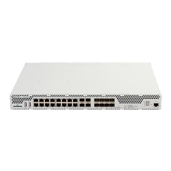
Page 16: Design
— Fig. 2.7 ESR-200 front panel Table 2.12 lists sizes, LEDs, and controls located on the front panel of ESR-100 and ESR-200 routers. Table 2.12 —Description of connectors, LEDs, and controls located on the front panel Front panel element Description SD memory card installation slot. - Page 17 2.4.2.2 ESR-100, ESR-200 rear panel The rear panel layout of ESR-100 and ESR-200 routers is depicted in Fig. 2.8 — Fig. 2.8 ESR-1000, rear panel Table 2.13 lists rear panel connectors of the router. Table 2.13 —Description of rear panel connectors of the router Description Earth bonding point of the device.
-
Page 18: Light Indication
2.4.3 Light Indication 2.4.3.1 ESR-1000, ESR-1200 light indication Gigabit Ethernet copper interface status is represented by two LEDs—green LINK/ACT LED and amber SPEED LED. Location of the copper interface LEDs is depicted in Fig. 2.11. SFP interface status is is represented by two LEDs—RX/ACT and TX/ACT—depicted in Fig. - Page 19 Backup power supply is missing or failed. 2.4.3.2 ESR-100/ESR-200 light indication Gigabit Ethernet copper interface and SFP interface statuses are represented by two LEDs—green LINK/ACT LED and amber SPEED LED. Location of the copper interface LEDs is depicted in Fig. 2.11. SFP interface status is depicted in Fig.
-
Page 20: Delivery Package
Delivery Package ESR-100 standard delivery package includes: ESR-100 router Power cable Console port connection cable (RJ-45 – DB9F) 19” rack mounting kit ... - Page 21 ESR-1000 standard delivery package includes: ESR-1000 router Power cable Console port connection cable (RJ-45 – DB9F) 19” rack mounting kit Documentation ESR-1200 standard delivery package includes: – ESR-1200 router; – power cable; – Console port connection cable (RJ-45 – DB9F); –...
-
Page 22: Installation And Connection
INSTALLATION AND CONNECTION This section describes installation of the device into a rack and connection to a power supply. Support brackets mounting The delivery package includes support brackets for rack installation and mounting screws to fix the device case on the brackets. To install the support brackets: —... -
Page 23: Device Rack Installation
Device rack installation To install the device to the rack: 1. Attach the device to the vertical guides of the rack. 2. Align mounting holes in the support bracket with the corresponding holes in the rack guides. Use the holes of the same level on both sides of the guides to ensure the device horizontal installation. -
Page 24: Esr-1000, Esr-1200 Power Module Installation
ESR-1000, ESR-1200 power module installation ESR-1000 router can operate with one or two power modules. The second power module installation is necessary when the device operates under strict reliability requirements. From the electric point of view, both places for power module installation are identical. In the context of device operation, the power module located closer to the edge is considered as the main module, and the one closer to the centre—as the backup module. -
Page 25: Sfp Transceiver Installation And Removal
SFP transceiver installation and removal Optical modules can be installed when the terminal is turned on or off. Transceiver installation 1. Insert the top SFP module into a slot with its open side down, and the bottom SFP module with its open side up. -
Page 26: Management Interfaces
— access 192.168.1.1/24. Trusted zone includes the following interfaces: For ESR-100: GigabitEthernet 1/0/2-4; For ESR-200: GigabitEthernet 1/0/2-8; For ESR-1000: GigabitEthernet 1/0/2-24; For ESR-1200: GigabitEthernet 1/0/2-16, TengigabitEthernet 1/0/3-8 By default, the user 'admin' with the password 'password' is defined in factory settings. -
Page 27: Initial Router Configuration
IP address from the provider. All incoming connections from this zone to the router are blocked. This security zone includes the following interfaces: For ESR-100 and ESR-200: GigabitEthernet 1/0/1; For ESR-1000 and ESR-1200: GigabitEthernet1/0/1, TengigabitEthernet1/0/1, TengigabitEthernet1/0/2. -
Page 28: Router Connection And Configuration
Security zone policies have the following configuration: Table 5.1 —Security zone policy description Traffic destination Traffic origin zone Traffic type Action zone Trusted Untrusted TCP, UDP, ICMP enabled Trusted Trusted TCP, UDP, ICMP enabled Trusted self TCP/23(Telnet), TCP/22(SSH), ICMP, enabled UDP/67(DHCP Server), UDP/123(NTP) Untrusted self... -
Page 29: Basic Router Configuration
To ensure the secure system access, you should change the password for the privileged 'admin' user. 'techsupport' account ('eltex' up to version 1.0.7) is required for service center specialist remote access. 'remote' account — RADIUS, TACACS+, LDAP authentication. - Page 30 5.2.2.2 Creation of new users Use the following commands to create a new system user or configure the username, password, or privilege level: esr(config)# username <name> esr(config-user)# password <password> esr(config-user)# privilege <privilege> esr(config-user)# exit Privilege levels 1–9 allow you to access the device and view its operation status, but the device configuration is disabled.
- Page 31 To ensure the correct IP address assigning for the interface, enter the following command when the configuration is applied: esr# show ip interfaces IP address Interface Type ------------------- --------------------------------- ------- 192.168.16.144/24 gigabitethernet 1/0/2.150 static Provider may use dynamically assigned addresses in their network. If the there is DHCP server in the network, you can obtain the IP address via DHCP protocol.
- Page 32 esr# configure esr(config)# object-group network clients esr(config-addr-set)# ip address-range 132.16.0.5-132.16.0.10 esr(config-addr-set)# exit esr(config)# object-group network gateway esr(config-addr-set)# ip address-range 40.13.1.22 esr(config-addr-set)# exit esr(config)# object-group service ssh esr(config-port-set)# port-range 22 esr(config-port-set)# exit esr(config)# security zone-pair untrusted self esr(config-zone-pair)# rule 10 esr(config-zone-rule)# action permit esr(config-zone-rule)# match protocol tcp esr(config-zone-rule)# match source-address clients esr(config-zone-rule)# match destination-address gateway...
-
Page 33: Firmware Update
FIRMWARE UPDATE Updating firmware via system resources To update the firmware, use any of the following servers: TFTP, FTP, SCP. Router firmware files obtained from the manufacturer should be allocated on the server. The router stores two copies of the firmware. To ensure the reliability of the firmware update procedure, only the copy that was not used for the last device startup is available for the update. -
Page 34: Updating Firmware Via Bootloader
esr# show bootvar Image Version Date Status After reboot ----- ------------------------- -------------------- ------------ ------------ 1.0.4 build 94[f812808] date 18/02/2015 time Active 16:12:54 1.0.4 build 94[f812808] date 18/02/2015 time Not Active 16:12:54 Use the following command to select the image: esr# boot system image-[1|2] 6. -
Page 35: Secondary Bootloader Update (U-Boot)
Using nae-0-3 device 10.100.100.1 10.100.100.2 TFTP from server ; our IP address is Filename 'esr1000/firmware'. Load address: 0xa800000060000000 Loading: TftpStart:TftpTimeoutMsecs = 10000, TftpTimeoutCountMax = 6 ################################################################# ################################################################# ################################################################# ######################### #################################### done Bytes transferred = 64453909 (3d77d15 hex) Device 0: MT29F8G08ABBCAH4 ... - Page 36 5. Launch firmware update procedure: BRCM.XLP316Lite Rev B0.u-boot# run upd_uboot (or «run tftp_update_uboot» - depends on the bootloader version) Using nae-1 device TFTP from server 10.100.100.1; our IP address is 10.100.100.2 Filename 'esr1000/u-boot.bin'. Load address: 0xa800000078020000 Loading: ########################################################### done Bytes transferred = 852648 (d02a8 hex) SF: Detected MX25L12805D with page size 256, total 16777216 bytes 16384 KiB MX25L12805D at 0:0 is now current device 6.
-
Page 37: Router Configuration Examples
ROUTER CONFIGURATION EXAMPLES VLAN Configuration VLAN (Virtual Local Area Network) is a logical (virtual) local area network that represents a group of devices which communicate on channel level regardless of their physical location. Objective 1: On the basis of the factory configuration, remove gi1/0/1 port from VLAN 2. —... - Page 38 Configuration has been successfully committed esr-1000# confirm Objective 3: Configure gi1/0/1 ports for packet transmission and reception in VLAN 2, VLAN 64, VLAN 2000 in trunk mode, configure gi1/0/2 port in access mode for VLAN 2 on ESR-100/ESR -200. — Fig. 7.3...
-
Page 39: Qinq Termination Configuration
QinQ termination configuration QinQ is a technology of packet transmission with two 802.1q tags. The technology is used for extending quantity of VLANs in data networks. 802.1q header, which is closer to payload, is an Inner Tag also known as C-VLAN (Custimer VLAN). 802.1q header, which is comes before C-VLAN, is an Outer Tag also known as S-VLAN (Service VLAN). -
Page 40: Command Privilege Configuration
Solution: Configure connection to RADIUS server and specify the key (password): esr# configure esr(config)# radius-server host 192.168.16.1 esr(config-radius-server)# key ascii-text encrypted 8CB5107EA7005AFF esr(config-radius-server)# exit Create authentication profile: esr(config)# aaa authentication login log radius Specify authentication mode used for Telnet protocol connection: esr(config)# line telnet esr(config-line-telnet)# login authentication log esr(config-line-telnet)# exit... -
Page 41: Dhcp Server Configuration
192.168.1.100-192.168.1.125 esr(config-dhcp-server)# default-lease-time 1:00:00 Configure transfer of additional network parameters to clients: default route: 192.168.1.1 domain name: eltex.loc DNS server list: DNS1: 172.16.0.1, DNS2: 8.8.8.8. esr(config-dhcp-server)# domain-name "eltex.loc" esr(config-dhcp-server)# default-router 192.168.1.1 esr(config-dhcp-server)# dns-server 172.16.0.1 8.8.8.8... - Page 42 esr(config-dhcp-server)# exit To enable IP address distribution from the configurable pool by DHCP server, IP interface should be created on the router that belongs to the same subnet as the pool addresses. esr(config)# interface gigabitethernet 1/0/1 esr(config-if-gi)# security-zone trusted esr(config-if-gi)# ip address 192.168.1.1/24 esr(config-if-gi)# exit To enable DHCP protocol message transmission to the server, you should create the respective port profiles including source port 68 and destination port 67 used by DHCP protocol and create the allowing...
-
Page 43: Destination Nat Configuration
Destination NAT configuration Destination NAT (DNAT) function includes destination IP address translation for packets transferred through the network gateway. DNAT is used for redirection of traffic, coming to a specific 'virtual' address in a public network, to a 'real' server in LAN located behind the network gateway. This function may be used for establishing a public access to servers located within the private network without any public network address. - Page 44 Proceed to DNAT configuration mode and create destination address and port pool that will be used for translation of packet addresses coming to address 1.2.3.4 from the external network. esr(config)# nat destination esr(config-dnat)# pool SERVER_POOL esr(config-dnat-pool)# ip address 10.1.1.100 esr(config-dnat-pool)# ip port 80 esr(config-dnat-pool)# exit Create 'DNAT' rule set which will be used for address translation.
-
Page 45: Source Nat Configuration
Source NAT configuration Source NAT (SNAT) function substitutes source address for packets transferred through the network gateway. When packets are transferred from LAN into public network, source address is substituted to one of the gateway public addresses. Additionally, source port substitution may be added to the source address. - Page 46 To transfer traffic from 'TRUST' zone into 'UNTRUST' zone, create a pair of zones and add rules allowing traffic transfer in this direction. Additionally, there is a check in place to ensure that data source address belongs to 'LOCAL_NET' address range in order to limit the access to public network. Rules are applied with enable command.
- Page 47 Objective 2: Configure access for users in LAN 21.12.2.0/24 to public network using Source NAT function without the firewall. Public network address range for SNAT 200.10.0.100-200.10.0.249. Fig. 7.6—Network structure Solution: Begin configuration with network interface configuration and disabling the firewall: esr(config)# interface gigabitethernet 1/0/1 esr(config-if-gi)# ip address 21.12.2.1/24 esr(config-if-gi)# ip firewall disable...
-
Page 48: Firewall Configuration
In order the router could response to the ARP requests for addresses from the public pool, you should launch ARP Proxy service. ARP Proxy service is configured on the interface that IP address from 'PUBLIC_POOL' public network address profile subnet belongs to: esr(config)# interface tengigabitethernet 1/0/1 esr(config-if-te)# ip nat proxy-arp PUBLIC_POOL —... - Page 49 For definition of rules for security zones, create 'LAN' address profile that includes addresses which are allowed to access WAN network and 'WAN' network address profile. esr(config)# object-group network WAN esr(config-object-group-network)# ip address-range 192.168.23.2 esr(config-object-group-network)# exit esr(config)# object-group network LAN esr(config-object-group-network)# ip address-range 192.168.12.2 esr(config-object-group-network)# exit esr(config)# object-group network LAN_GATEWAY...
-
Page 50: Access List (Acl) Configuration
esr(config-zone-rule)# match destination-address LAN esr(config-zone-rule)# match source-address LAN_GATEWAY esr(config-zone-rule)# enable esr(config-zone-rule)# exit esr(config-zone-pair)# exit esr(config)# exit Configuration changes will take effect when the following commands are executed: esr# commit Configuration has been successfully committed esr# confirm Configuration has been successfully confirmed esr# To view port membership in zones, use the following command: esr# show security zone... -
Page 51: Static Routes Configuration
esr# commit Configuration has been successfully committed esr# confirm Configuration has been successfully confirmed esr# To view the detailed information on access control list, use the following command: esr# show ip access-list white 7.10 Static routes configuration Static routing is a type of routing in which routes are defined explicitly during the router configuration without dynamic routing protocols. - Page 52 For gi1/0/3 interface, specify 128.107.1.2/30 address and 'WAN' zone. R1 will be connected to the Internet through this interface: R1(config)# interface gi1/0/3 R1(config-if-gi)# security-zone WAN R1(config-if-gi)# ip address 128.107.1.2/30 R1(config-if-gi)# exit Create a route for interaction with 10.0.0.0/8 network using R2 device (192.168.100.2) as a gateway: R1(config)# ip route 10.0.0.0/8 192.168.100.2 Create a route for interaction with the Internet using provider gateway (128.107.1.1) as a nexthop:...
-
Page 53: Mlpp Configuration
To check the routing table, use the following command: esr# show ip route 7.11 MLPP configuration Multilink PPP (MLPPP) is an aggregated channel that encompasses methods of traffic transition via multiple physical channels while having a single logical connection. This option allows to enhance bandwidth and enables load balancing. -
Page 54: Bridge Configuration
7.12 Bridge configuration Bridge is a method of connection for two Ethernet segments on data-link level without any higher level protocols, such as IP. Packet transmission is based on Ethernet addresses, not on IP addresses. Given that the transmission is performed on data-link level (Level 2 of the OSI model), higher level protocol traffic passes through the bridge transparently. - Page 55 Objective 2: Configure routing between VLAN 50 (10.0.50.0/24) and VLAN 60 (10.0.60.1/24). VLAN — 50 should belong to 'LAN1', VLAN 60 to 'LAN2', enable free traffic transmission between zones. — Fig. 7.11 Network structure Solution: Create VLAN 50 and 60: esr(config)# vlan 50,60 esr(config-vlan)# exit Create 'LAN1' and 'LAN2' security zones.
-
Page 56: Rip Configuration
esr(config-zone-rule)# action permit esr(config-zone-rule)# match protocol any esr(config-zone-rule)# match source-address any esr(config-zone-rule)# match destination-address any esr(config-zone-rule)# enable esr(config-zone-rule)# exit esr(config-zone-pair)# exit esr(config)# security zone-pair LAN2 LAN1 esr(config-zone-pair)# rule 1 esr(config-zone-rule)# action permit esr(config-zone-rule)# match protocol any esr(config-zone-rule)# match source-address any esr(config-zone-rule)# match destination-address any esr(config-zone-rule)# enable esr(config-zone-rule)# exit... -
Page 57: Ospf Configuration
Enter the RIP configuration mode: esr(config)# router rip Define subnets that will be announced by the protocol: 115.0.0.0/24, 14.0.0.0/24 and 10.0.0.0/24: esr(config-rip)# network 115.0.0.0/24 esr(config-rip)# network 14.0.0.0/24 esr(config-rip)# network 10.0.0.0/24 To announce static routes by the protocol, execute the following command: esr(config-rip)# redistribute static Configure timer, responsible for routing information transmission: esr(config-rip)# timers update 25... - Page 58 — Fig. 7.13 Network structure Solution: Pre-configure IP addresses on interfaces according to the network structure shown in Fig. 7.13. Create OSPF process with identifier 10 and proceed to the OSPF protocol configuration mode: esr(config)# router ospf 10 Create and enable the required area: esr(config-ospf)# area 1.1.1.1 esr(config-ospf-area)# enable esr(config-ospf-area)# exit...
- Page 59 Configuration changes will take effect when the configuration is applied: esr# commit Configuration has been successfully committed esr# confirm Configuration has been successfully confirmed Objective 2: Change 1.1.1.1 area type, area should be stub. Stub router should announce routes received via RIP. —...
-
Page 60: Bgp Configuration
For R1 router, proceed to 1.1.1.1 area configuration mode: esr(config-ospf)# area 1.1.1.1 Create and enable virtual link with the identifier 0.0.0.3: esr(config-ospf-area)# virtual-link 0.0.0.3 esr(config-ospf-vlink)# enable For R3 router, proceed to 1.1.1.1 area configuration mode: esr(config-ospf)# area 1.1.1.1 Create and enable virtual link with the identifier 0.0.0.1: esr(config-ospf-area)# virtual-link 0.0.0.1 esr(config-ospf-vlink)# enable Configuration changes will take effect when the configuration is applied:... - Page 61 Objective: Configure BGP on the router with the following parameters: — Fig. 7.16 Network structure – proprietary subnets: 80.66.0.0/24, 80.66.16.0/24; – announcing of directly connected subnets; – proprietary AS 2500; — – first neighbouring subnet 219.0.0.0/30, proprietary IP address 219.0.0.1, neighbour IP address 219.0.0.2, AS 2500;...
- Page 62 esr(config-bgp-af)# neighbor 219.0.0.2 esr(config-bgp-neighbor)# remote-as 2500 esr(config-bgp-neighbor)# enable esr(config-bgp-neighbor)# exit Enable protocol operation: esr(config-bgp-af)# enable esr(config-bgp-af)# exit esr(config)# exit Configuration changes will take effect when the configuration is applied: esr# commit Configuration has been successfully committed esr# confirm Configuration has been successfully confirmed esr# To view BGP peer information, use the following command: esr# show ip bgp 2500 neighbors...
-
Page 63: Pbr Routing Policy Configuration
7.16 PBR routing policy configuration 7.16.1 Route-map for BGP configuration Route-maps may serve as filters processing routing information when it is received from or sent to the neighbouring device. Processing may include filtering based on various route criteria and setting attributes (MED, AS-PATH, community, LocalPreference, etc.) for the respective routes. - Page 64 Map the policy to routing information: esr(config-bgp-neighbor)# route-map from-as20 in Objective 2: For the whole transmitted routing information (from community 2500:25), assign MED equal to 240 and define EGP routing information source: First: Configure BGP with AS 2500 on ESR Solution: Create a policy: esr(config)# route-map to-as20...
-
Page 65: Route-Map Based On Access Control Lists (Policy-Based Routing)
7.16.2 Route-map based on access control lists (Policy-based routing) — Fig. 7.18 Network structure Objective 1: Distribute traffic between Internet service providers based on user subnets. First, do the following: – Assign IP address to interfaces. Route traffic from addresses 10.0.20.0/24 through ISP1 (184.45.0.150), and traffic from addresses 10.0.30.0/24 trough ISP2 (80.16.0.23). - Page 66 esr(config-route-map-rule)# match ip access-group sub20 Specify nexthop for sub20: esr(config-route-map-rule)# action set ip next-hop verify-availability 184.45.0.150 10 esr(config-route-map-rule)# action set ip next-hop verify-availability 80.16.0.23 esr(config-route-map-rule)# exit esr(config-route-map)# exit Rule 1 should provide traffic routing from the network 10.0.20.0/24 to address 184.45.0.150, and in —...
-
Page 67: Gre Tunnel Configuration
7.17 GRE tunnel configuration GRE (Generic Routing Encapsulation) is a network packet tunnelling protocol. Its main purpose is to encapsulate packets of the OSI model network layer into IP packets. GRE may be used for VPN establishment on 3rd level of OSI model. In ESR router implemented static unmanageable GRE tunnels, i.e. tunnels are created manually via configuration on local and remote hosts. - Page 68 To apply configuration changes, execute the following commands: esr# commit Configuration has been successfully committed esr# confirm Configuration has been successfully confirmed When settings are applied, traffic will be encapsulated into the tunnel and sent to the partner regardless of their GRE tunnel existence and settings validity. Alternatively, you may specify the following parameters for GRE tunnel: ...
-
Page 69: L2Tpv3 Tunnel Configuration
7.18 L2TPv3 tunnel configuration L2TPv3 (Layer 2 Tunneling Protocol Version 3) is a protocol used for tunnelling of 2nd level OSI model packets between two IP nodes. IP or UDP is used as an encapsulation protocol. L2TPv3 may be used as an alternative to MPLS P2P L2VPN (VLL) for L2 VPN establishment. - Page 70 Specify identifiers for session inside the tunnel for local and remote sides: esr(config-l2tpv3)# local session-id 100 esr(config-l2tpv3)# remote session-id 200 Define the inherence of L2TPv3 tunnel to a bridge that should be mapped to remote office network (for bridge configuration, see Paragraph 7.11): esr(config-l2tpv3)# bridge-group 333 Enable previously created tunnel and exit: esr(config-l2tpv3)# enable...
-
Page 71: Ipsec Vpn Configuration
7.19 IPsec VPN configuration IPsec is a set of protocols that enable security features for data transferred via IP protocol. This set of protocols allows for identity validation (authentication), IP packet integrity check and encryption, and also includes protocols for secure key exchange over the Internet. —... - Page 72 esr(config-object-group-service)# port-range 500 esr(config-object-group-service)# exit Create a static route to the remote LAN. For each subnet located behind an IPsec tunnel, specify a route via VTI tunnel: esr(config)# ip route 192.0.2.0/24 tunnel vti 1 Create IKE protocol profile. In the profile, select Diffie-Hellman group 2, AES 128 bit encryption algorithm, MD5 authentication algorithm.
- Page 73 esr(config)# exit 2. R2 configuration Configure external network interface and identify its inherence to a security zone: esr# configure esr(config)# interface gi 1/0/1 esr(config-if)# ip address 120.11.5.1/24 esr(config-if)# security-zone untrusted esr(config-if)# exit Create VTI tunnel. Traffic will be routed via VTI into IPsec tunnel. Specify IP addresses of WAN border interfaces as a local and remote gateways: esr(config)# tunnel vti 1 esr(config-vti)# remote address 180.100.0.1...
-
Page 74: Policy-Based Ipsec Vpn Configuration
Create security parameters' profile for IPsec tunnel. For the profile, select AES 128 bit encryption algorithm, MD5 authentication algorithm. Use the following parameters to secure IPsec tunnel: esr(config)# security ipsec proposal ipsec_prop1 esr(config-ipsec-proposal)# authentication algorithm md5 esr(config-ipsec-proposal)# encryption algorithm aes128 esr(config-ipsec-proposal)# exit Create policy for IPsec tunnel. - Page 75 Create IKE profile. In the profile, specify Diffie-Hellman group as 2, encryption algorithm - AES 128 bit, authentication algorithm - MD5. This security parameters is used for protection of IKE connection: esr(config)# security ike proposal ike_prop1 esr(config-ike-proposal)# dh-group 2 esr(config-ike-proposal)# authentication algorithm md5 esr(config-ike-proposal)# encryption algorithm aes128 esr(config-ike-proposal)# exit Create IKE protocol policy.
- Page 76 esr# configure esr(config)# interface gi 1/0/1 esr(config-if)# ip address 120.11.5.1/24 esr(config-if)# security-zone untrusted esr(config-if)# exit Create ISAKMP port profile in order to configure security zone rules: esr(config)# object-group service ISAKMP esr(config-addr-set)# port-range 500 esr(config-addr-set)# exit Create IKE profile. In the profile, specify Diffie-Hellman group as 2, encryption algorithm - AES 128 bit, authentication algorithm - MD5.
-
Page 77: Lt-Tunnels Configuration
esr(config)# security ipsec vpn ipsec1 esr(config-ipsec-vpn)# mode ike esr(config-ipsec-vpn)# ike establish-tunnel immediate esr(config-ipsec-vpn)# ike gateway ike_gw1 esr(config-ipsec-vpn)# ike ipsec-policy ipsec_pol1 esr(config-ipsec-vpn)# enable esr(config-ipsec-vpn)# exit esr(config)# exit You can view the state of the tunnel using following command: esr# show security ipsec vpn status ipsec1 You can view the configuration of the tunnel using following command: esr# show security ipsec vpn configuration ipsec1 It is necessery to enable ESP and ISAKMP (UDP - port 500) in firewall. -
Page 78: Configuring Remote Access To Corporate Network Via Pptp Protocol
Designate LT-tunnel from VRF, which is necessary to establish link with, for each LT-tunnel and activate them. esr(config)# tunnel lt 1 esr(config-lt)# peer lt 2 esr(config-lt)# enable esr(config-lt)# exit esr(config)# tunnel lt 2 esr(config-lt)# peer lt 1 esr(config-lt)# enable esr(config-lt)# exit If NONE of dynamic routing protocols works in VRF, specify static routes for each VRF: esr(config)# ip route vrf vrf_1 0.0.0.0/0 192.168.100.2 esr(config)# ip route vrf vrf_2 0.0.0.0/0 192.168.100.1... - Page 79 esr# configure esr(config)# object-group network pptp_outside esr(config-object-group-network)# ip address-range 120.11.5.1 esr(config-object-group-network)# exit Create address profile that contains local gateway address: esr(config)# object-group network pptp_local esr(config-object-group-network)# ip address-range 10.10.10.1 esr(config-object-group-network)# exit Create address profile that contains client addresses: esr(config)# object-group network pptp_remote esr(config-object-group-network)# ip address-range 10.10.10.5-10.10.10.25 esr(config-object-group-network)# exit Create address profile that contains DNS servers:...
-
Page 80: Configuring Remote Access To Corporate Network Via L2Tp/Ipsec Protocol
To end PPTP server session for user 'fedor', use one of the following commands: esr# clear remote-access session pptp username fedor esr# clear remote-access session pptp server remote-workers username fedor To view PPTP server configuration, use the following command: esr# show remote-access configuration pptp remote-workers In addition to PPTP server creation, you should open TCP port 1723 designed for connection handling and enable GRE protocol (47) for the tunnel traffic in the firewall. - Page 81 esr(config)# object-group network pptp_dns esr(config-object-group-network)# ip address-range 8.8.8.8 esr(config-object-group-network)# ip address-range 8.8.4.4 esr(config-object-group-network)# exit Create L2TP server and map profiles listed above to it: esr(config)# remote-access l2tp remote-workers esr(config-l2tp)# local-address ip-address 10.10.10.1 esr(config-l2tp)# remote-address address-range 10.10.10.5-10.10.10.15 esr(config-l2tp)# outside-address ip-address 120.11.5.1 esr(config-l2tp)# dns-server object-group l2tp_dns Select authentication method for L2TP server users: esr(config-l2tp)# authentication mode radius...
-
Page 82: Configuring Remote Access To Corporate Network Via Openvpn Protocol
7.23 Configuring remote access to corporate network via OpenVPN protocol OpenVPN is a sophisticated tool based on SSL that implements Virtual Private Networks (VPN), enables remote access and solves many different tasks related to data transmission security. Objective: Configure Open VPN server in L3 mode on a router for remote user connection to LAN. ... -
Page 83: Dual-Homing Configuration
Specify previously imported certificates and keys that will be used with OpenVPN server: esr(config-openvpn)# certificate ca ca.crt esr(config-openvpn)# certificate dh dh.pem esr(config-openvpn)# certificate server-key server.key esr(config-openvpn)# certificate server-crt server.crt esr(config-openvpn)# certificate ta ta.key Specify security zone that user sessions will be related to: esr(config-openvpn)# security-zone VPN Select aes128 encryption algorithm: esr(config-openvpn)# encryption algorithm aes128... -
Page 84: Qos Configuration
Objective: Establish redundancy of the ESR router L2 connections for VLAN 50-55 using SW1 and SW2 devices. — Fig. 7.25 Network structure Solution: 1. First, do the following: Create VLAN 50-55: esr-1000(config)# vlan 50-55 You should disable STP for gigabitethernet 1/0/9 and gigabitethernet 1/0/10 interfaces, i.e. these protocols cannot operate simultaneously. -
Page 85: Basic Qos
7.25.1 Basic QoS Objective: Configure the following restrictions on gigabitethernet 1/0/8 interface: transfer DSCP 22 traffic into 8th priority queue, DSCP 14 traffic into 7th weighted queue, limit transfer rate to 60Mbps for 7th queue. — Fig. 7.26 Network structure Solution: In order to make 8th queue a priority queue, and 1st to 7th queues weighted ones, limit the quantity of priority queues to 1. -
Page 86: Extended Qos
7.25.2 Extended QoS Objective: Classify incoming traffic by a subnet (10.0.11.0/24, 10.0.12.0/24), label it by DSCP (38 and 42) and segregate by a subnet (40Mbps and 60Mbps), limit general bandwidth to 250Mbps, process the rest of traffic using SFQ mechanism. —... - Page 87 esr(config-class-policy-map)# exit esr(config-policy-map)# class fl2 esr(config-class-policy-map)# shape average 60000 esr(config-class-policy-map)# exit For the rest of traffic, configure a class with SFQ mode: esr(config-policy-map)# class class-default esr(config-class-policy-map)# mode sfq esr(config-class-policy-map)# fair-queue 800 esr(config-class-policy-map)# exit esr(config-policy-map)# exit Enable QoS on the interfaces, policy on gi 1/0/19 interface ingress for classification purposes and gi1/0/20 egress for applying restrictions and SFQ mode for default class: esr(config)# interface gigabitethernet 1/0/19 esr(config-if-gi)# qos enable...
-
Page 88: Mirroring Configuration
7.26 Mirroring configuration Traffic mirroring is a feature of the router that allows for redirection of traffic from a specific port of the router to another port of the same router (local mirroring) or to a remote device (remote mirroring). Objective: Establish remote mirroring of traffic through VLAN 50 from gi1/0/11 interface to be sent to server for processing purposes. -
Page 89: Netflow Configuration
7.27 Netflow configuration Netflow is a network protocol designed for traffic accounting and analysis. Netflow allows to transfer traffic information (source and destination address, port, quantity of information) from the network equipment (sensor) to the collector. Common server may serve as a collector. Objective: Establish accounting for traffic from gi1/0/1 interface to be sent to the server via gi1/0/8 interface for processing purposes. -
Page 90: Sflow Configuration
7.28 sFlow configuration Sflow is a computer network, wireless network and network device monitoring standard designed for traffic accounting and analysis. Objective: Establish accounting for traffic between 'trusted' and 'untrusted' zones. — Fig. 7.30 Network structure Solution: Create two security zones for ESR networks: esr# configure esr(config)# security zone TRUSTED esr(config-zone)# exit... -
Page 91: Lacp Configuration
esr(config-zone-pair-rule)# match protocol any esr(config-zone-pair-rule)# match source-address any esr(config-zone-pair-rule)# match destination-address any esr(config-zone-pair-rule)# enable Enable sFlow on the router: еsr(config)# sflow enable Configuration changes will take effect when the configuration is applied: esr# commit Configuration has been successfully committed esr# confirm Configuration has been successfully confirmed sFlow configuration for traffic accounting from the interface is performed by analogy to 7.27 Netflow configuration. -
Page 92: Vrrp Configuration
Configuration has been successfully committed esr# confirm Configuration has been successfully confirmed Further port-channel configuration is performed by analogy to the common physical interface. 7.30 VRRP configuration VRRP (Virtual Router Redundancy Protocol) is a network protocol designed for increased availability of routers, acting as a default gateway. - Page 93 Configuration has been successfully committed R1# confirm Configuration has been successfully confirmed Configure R2 in the same manner. Objective 2: Establish virtual gateways for 192.168.20.0/24 subnet in VLAN 50 and 192.168.1.0/24 in VLAN 60 using VRRP with Master sync feature. To do this, you have to group VRRP processes. IP addresses 192.168.1.1 and 192.168.20.1 are used as virtual gateways.
-
Page 94: Vrrp Tracking Configuration
Enable VRRP: R1(config-subif)# vrrp R1(config-subif)# exit Configure VRRP for 192.168.20.0/24 subnet in the created sub-interface. Specify unique VRRP identifier: R1(config-sub)#interface gi 1/0/6.60 R1(config-subif)# vrrp id 20 Specify virtual gateway IP address 192.168.20.1: R1(config-subif)# vrrp ip 192.168.20.1 Specify VRRP group identifier: R1(config-subif)# vrrp group 5 Enable VRRP: R1(config-subif)# vrrp... - Page 95 Initial configurations of the routers: Router R1: hostname R1 interface gigabitethernet 1/0/1 switchport forbidden default-vlan exit interface gigabitethernet 1/0/1.741 ip firewall disable ip address 192.168.0.2/24 vrrp ip 192.168.0.1/24 vrrp exit interface gigabitethernet 1/0/2 switchport forbidden default-vlan exit interface gigabitethernet 1/0/2.742 ip firewall disable ip address 192.168.1.1/30 exit...
-
Page 96: Vrf Lite Configuration
vrrp ip 192.168.0.1/24 vrrp exit interface gigabitethernet 1/0/2 switchport forbidden default-vlan exit interface gigabitethernet 1/0/2.742 ip firewall disable ip address 192.168.1.2/30 exit interface gigabitethernet 1/0/4 ip firewall disable ip address 10.0.1.1/24 exit Solution: There is no need in any changes in router R2, since subnet 10.0.1.0/24 is terminated on it and as soon as router R1 is vrrp master, packets will be transmitted to corresponding interface. - Page 97 Solution: Create VRF: esr(config)# ip vrf bit esr(config-vrf)# exit Create security zone: esr(config)# security zone vrf-sec esr(config-zone)# ip vrf forwarding bit esr(config-zone)# exit Create rule for a pair of zones and allow all TCP/UDP traffic: esr(config)# security zone-pair vrf-sec vrf-sec esr(config-zone-pair)# rule 1 esr(config-zone-rule)# match source-address any esr(config-zone-rule)# match destination-address any...
-
Page 98: Multiwan Configuration
esr# show ip route vrf bit 7.33 MultiWAN configuration MultiWAN technology establishes a fail-safe connection with redundancy of links from multiple providers and solves the problem involving traffic balancing between redundant links. Objective: Configure route to the server (108.16.0.1/28) with the load balancing option. —... - Page 99 Create integrity check target: esr(config-target-list)# target 1 Specify address to be checked, enable check for the specified address and exit: еsr(config-wan-target)# ip address 8.8.8.8 еsr(config-wan-target)# enable еsr(config-wan-target)# exit Configure interfaces. In te1/0/1 interface configuration mode, specify nexthop: еsr(config)# interface tengigabitethernet 1/0/1 еsr(config-if)# wan load-balance nexthop 203.0.0.1 In te1/0/1 interface configuration mode, specify a list of targets for link check: еsr(config-if)# wan load-balance target-list google...
-
Page 100: Snmp Configuration
7.34 SNMP configuration SNMP (Simple Network Management Protocol)is a protocol designed for device management in IP networks featuring TCP/UDP architecture. SNMP provides management data as variables that describe the configuration of a system being managed. Objective: Configure SNMPv3 server with authentication and data encryption for 'admin' user. ESR router IP address: 192.168.52.41, server IP address: 192.168.52.8. -
Page 101: Bras (Broadband Remote Access Server) Configuration
Fig. 7.3 – Network structure Solution: SoftWLC server keeps accounts data and tariff plan parameters. You can obtain more detailed information on installation and configuring SoftWLC server using following links: http://kcs.eltex.nsk.ru/articles/960 general article of SoftWLC http://kcs.eltex.nsk.ru/articles/474 SoftWLC installation from repositories. - Page 102 Location parameter (see bridge 2 configuration). The module which is control AAA operations is based on eltex-radius and available by SoftWLC IP address. Numbers of ports for authentication and accounting in the example below are the default values for SoftWLC.
- Page 103 Specify web resources which are available without authorization: esr(config)# object-group url defaultservice esr(config-object-group-url)# url http://eltex.nsk.ru esr(config-object-group-url)# exit The URL filtering lists are kept on SoftWLC server (you need to change only IP address of SoftWLC server, if addressing is different from the example. Leave the rest of URL without changes): esr(config)# subscriber-control filters-server-url http://192.0.2.20:7070/Filters/file/...
- Page 104 esr(config-subscriber-control)# bypass-traffic-acl DHCP esr(config-subscriber-control)# default-service esr(config-subscriber-default-service)# class-map INTERNET esr(config-subscriber-default-service)# filter-name local defaultservice esr(config-subscriber-default-service)# filter-action permit esr(config-subscriber-default-service)# default-action redirect http://192.0.2.20:8080/eltex_portal/ esr(config-subscriber-default-service)# session-timeout 3600 esr(config-subscriber-default-service)# exit esr(config-subscriber-control)# enable esr(config-subscriber-control)# exit Configure rules for transition among security zones. esr(config)# object-group service telnet esr(config-object-group-service)# port-range 23 esr(config-object-group-service)# exit esr(config)# object-group service ssh...
- Page 105 esr(config-zone-pair-rule)# match source-port dhcp_client esr(config-zone-pair-rule)# match destination-port dhcp_server esr(config-zone-pair-rule)# enable esr(config-zone-pair-rule)# exit esr(config-zone-pair)# exit Enable ICMP transmission to the device. For BRAS operation you need to open ports for web proxying - TCP 3129/3128 (NetPortDiscovery Port/Active API Server port: esr(config)# object-group service bras esr(config-object-group-service)# port-range 3129 esr(config-object-group-service)#...
- Page 106 esr# commit Configuration has been successfully committed esr# confirm Configuration has been successfully confirmed ESR Series Routers Operation Manual...
-
Page 107: Frequently Asked Questions
FREQUENTLY ASKED QUESTIONS Configuration changes will take effect when the configuration is applied: esr# commit Configuration has been successfully committed esr# confirm Configuration has been successfully confirmed Receiving of routes, which are configured in VRF via BGP or/and OSPF, failed. The neighboring is successfully installed, but record of routes in RIB is denied: %ROUTING-W-KERNEL: Can not install route. - Page 108 How to configure ip-prefix-list 0.0.0.0./0? Example of prefix-list configuration is shown below. The configuration allows route reception by default. esr(config)# ip prefix-list eltex esr(config-pl)# permit default-route Problem of asynchronuous traffic transmission is occurred In case of asynchronous routing, Firewall will forbid "incorrect" ingress traffic (which does not open new connection and does not belong any established connection) for security reasons.
- Page 109 +7(383) 274-47-87 +7(383) 272-83-31 E-mail: techsupp@eltex.nsk.ru Visit Eltex official website to get the relevant technical documentation and software, benefit from our knowledge base, send us online request or consult a Service Centre Specialist in our technical forum. http://www.eltex.nsk.ru/en/support/downloads/ http://www.eltex.nsk.ru/en/search/ http://www.eltex.nsk.ru/en/support/knowledge/...
Need help?
Do you have a question about the ESR-100 and is the answer not in the manual?
Questions and answers