FUTABA T16SZ Instruction Manual
18-channel digital proportional r/c system
Hide thumbs
Also See for T16SZ:
- Instruction manual (185 pages) ,
- Manual (13 pages) ,
- Instruction manual (187 pages)
Table of Contents
Advertisement
Advertisement
Table of Contents

Related Manuals for FUTABA T16SZ


Summary of Contents for FUTABA T16SZ
- Page 1 18-Channel Digital Proportional R/C System INSTRUCTION MANUAL 1M23N32902...
-
Page 2: Table Of Contents
●If the receiver's voltage does not display on the transmitter ..........43 BEFORE USE ........... 11 ●Range testing your R/C system...... 44 ●Features of T16SZ ......... 11 ●Contents and technical specifications ... 12 Model Basic Setting Procedure ......45 ●Multicopter/Robot specifications ....12 Airplane ............ - Page 3 ●Curve setting operation ........ 172 Aileron differential........129 ●Switch selection method ....... 177 Flap setting ............ 130 AIL → Camber flap ........131 ●Updating ............181 AIL → Brake flap ......... 132 ●T14SG/FX-22 ⇒ T16SZ DATA ....183 Aileron → Rudder ........133...
-
Page 4: Introduction
Email: futabaservice@hobbico.com Outside North America Please contact your Futaba importer in your region of the world to assist you with any questions, problems or service needs. Please recognize that all information in this manual, and all support availability, is based upon the systems sold in North America only. -
Page 5: Application, Export, And Modification
Prior approval of the appropriate government authorities may be required. If you have purchased this product from an exporter outside your country, and not the authorized Futaba distributor in your country, please contact the seller immediately to determine if such export regulations have been met. - Page 6 This radio transmitter (IC: 2914D-T16SZ) has been approved by Industry Canada to operate with the antenna types listed below with the maximum permissible gain indicated. Antenna types not included in this list, having a gain greater than the maximum gain indicated for that type, are strictly prohibited for use with this device.
-
Page 7: Definitions Of Symbols
Use of this product with other than models may be restricted by Export and Trade Control Regulations. 3. Modification, adjustment, and parts replacement: Futaba is not responsible for unauthorized modification, adjustment, or replacement of parts on this product. ■ No part of this manual may be reproduced in any form without prior permission. - Page 8 Do not fly at the following places: Always check operation of each control surface and perform a range test before each flying ses- ■ Near another radio control flying field. sion. Also, when using the trainer function, check ■ Near or above people. the operation of both the teacher and student ■...
- Page 9 ■ Charging the battery past the specified value may If the battery liquid should get in your eyes, do cause a fire, combustion, rupture, or liquid leakage. not rub your eyes, but immediately wash them When quick charging, do not charge the battery above with tap water or other clean water and get treat- ed by a doctor.
-
Page 10: Storage And Disposal Precautions
ESC, battery, etc. ■ If left in such an environment, the plastic may be damaged. ■ Futaba is not responsible for damage sustained by combination with parts other than Futaba Genuine ■ Since the metal parts of the case may corrode, always Parts. -
Page 11: Before Use
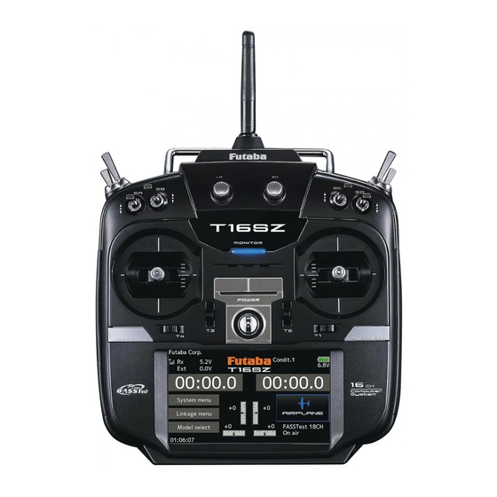
FASSTest is a maximum 18 channels 2.4GHz dedicated system. Color touch screen LCD T16SZ has a HVGA 4.3inch full color Backlight LCD touch screen. The screen is manufactured of a transflective construction which enables both indoor and outdoor visibility. S.BUS2 system By using the S.BUS2 system multiple servos, gyros and telemetry sensors are easily installed with a... -
Page 12: Contents And Technical Specifications
You cannot use the self-neutral throttle stick for R/C airplanes, helicopters, and certain multi-copters. Allowing the engine/motor to reach middle speed via automatic throttle stick return is very dangerous. If using the T16SZ for R/C airplanes and helicopters, you must change the throttle stick to the ratchet type. < Before Use >... -
Page 13: Accessories
: SBS-01/02G] [Voltage sensor : SBS-01V] [S.BUS servo sensor : SBS-01S] [Current sensor : SBS-01C] • Neckstrap - a neckstrap may be connected to your T16SZ system to make it easier to handle and improve your flying precision since your hands won’t need to support the transmitter’s weight. -
Page 14: Transmitter Controls
Transmitter controls ● Monitor LED ● Antenna ● Carrying handle ● Dial LD.RD ● Switch ● Switch SA.SB.SE.SF SC.SD.SG.SH ● Slide lever ● Slide lever ● Stick ● Stick ● Power Switch ● Digital trim T1-T4 ● Hook ● HOME/EXIT Button ●... -
Page 15: Transmitter's Antenna
Transmitter's antenna As with all radio frequency transmissions, the strongest area of signal transmission is from the sides of the transmitter's antenna. As such, the antenna should not be pointed directly at the model. If your flying style creates this situation, easily move the antenna to correct this situation. If you fly with your Low power transmitter facing the... -
Page 16: Switch (Sa-Sh)
Switch (SA-SH) SF : SH : 2 positions; Alternate; 2 positions; Momentary; Long lever Long lever SE : SG : 3 positions; Alternate; 3 positions; Alternate; Short lever Short lever SA : SD : 3 positions; Alternate; 3 positions; Alternate; Short lever Short lever SB :... -
Page 17: Volume (Ld, Rd)
LS (right), RS (Left): The Linear Slider LS and RS offer analog input. *The T16SZ transmitter beeps when the lever comes to the center. *You can select a slide lever and set the movement direction on the setting screen of mixing functions. -
Page 18: Digital Trims (T1-T4)
Digital Trims T1-T4 This transmitter is equipped with 4 digital trims. Each time you press a trim button, the trim position moves one step. If you continue pressing it, the trim position starts to move faster. In addition, when the trim position returns to the center, the tone will change. -
Page 19: Transmitter Nimh Battery Ht5F1800B
Transmitter NiMH Battery HT5F1800B Installing/removing the HT5F1800B ③ Connect the battery connector. ① A side battery cover is opened. Battery cover ④ Close the battery cover completely. ② Install the battery into the transmitter. This 2P connector connects HT5F1800B to the transmitter. NiMH Battery <... - Page 20 Do not use the transmitter the transmitter. as it is. Send it to the Futaba service center. 2. Plug the charger into an AC outlet. 3. Check that the charging LED lights.
-
Page 21: How To Turn Transmitter Power On/Off
How to turn transmitter power ON/OFF When turning on the power, the T16SZ transmitter will begin emitting RF automatically after it confirms the surrounding RF conditions. The status of the transmitter is displayed by LED at the upper part of the front of a T16SZ. -
Page 22: Touch Panel
Touch Panel Tapping the settings buttons for Tap the panel with your finger to enter each value on the settings screen data. will cause value input buttons to appear at the top of the panel. *Plastic film is attached to the Touch Panel. Please be careful so that you don't scratch the Touch Panel with anything hard such as a metal object. -
Page 23: Panel Lock
CAUTION The T16SZ's touch screen is very sensitive. To avoid accidentally activating it during a flight, it is suggested that it be locked. Due to the touch screen's sensitivity, allowing it to be touched... -
Page 24: Monitor Led Display
Monitor LED display The status of the transmitter is displayed by LED at the upper part of the front of a T16SZ. FASSTest mode → Light Blue light FASST mode → Green light FHSS mode → Yellow-green light RF-OFF → Violet light Starting →... -
Page 25: Stick Control (Airplane Example)
Stick control : Airplane Example *Example Stick Mode2 A general model example. (There is also a different operational model.) Roll Axis Control Pitch Axis Control Right roll Nose Up The right aileron is up. Elevator stick The left aileron Aileron stick is down. -
Page 26: Stick Control (Helicopter Example)
Stick control : Helicopter Example *Example Stick Mode2 A general model example. (There is also a different operational model.) Pitch Axis Control Roll Axis Control Right roll Nose Up Elevator stick Aileron stick To the right (moved to the bottom) Level flight Level flight Neutral... -
Page 27: Stick Control (Multicopter Example)
Stick control : Multicopter Example *Example Stick Mode2 A general model example. (There is also a different operational model.) Roll Axis Control Pitch Axis Control Right roll Nose Up Right slide Elevator stick Aileron stick Back slide To the right (moved to the bottom) Hovering Level flight... -
Page 28: Stick Adjustment
Stick Adjustment Adjustment of the stick lever length You can adjust the length of stick levers as you like. It is recommended to adjust the length of the sticks in line with your hand size. Lever head Lever head Side cover 1. -
Page 29: Sd Card
The T16SZ transmitter model data can be stored by using any commonly found SD card. When T16SZ transmitter update software is released, the software is updated using an SD card. The T16SZ is capable of using SD and SDHC cards (SD:32MB-2GB SDHC:4GB-32GB). - Page 30 As the SD card is a precision device, do Battery cover not use excessive force when inserting. -When a SD card is installed in the T16SZ transmitter, a folder called "Futaba" is cre- ated. Folders called "LOG" and "MODEL" are created in this folder. The "MODEL"...
-
Page 31: Connector/Plug
Connector/Plug S.BUS connector (S.I/F) When using an S.BUS servo and telemetry sensor, connect them both here. Earphone plug Earphone Connecting a stereo headphone to this plug, the Plug speech information of telemetry can be heard. Charge Plug Connector for battery charger This is the connector for charging the NiMH battery HT5F1800B that is installed in the transmitter. -
Page 32: Receiver Nomenclature
Receiver nomenclature DANGER Before using the receiver, be sure to read the precautions listed in the following pages. Don't attach a connector as shown in the preceding illustration. Receiver R7008SB *It will short-circuit if connected in this way. A short circuit across the battery terminals may cause abnormal heating, fire and burns. - Page 33 Link button for more than 2 seconds. 6. Once locked into the correct mode the The T16SZ has the ability to link to two LED will change to a solid color. R7008SB receivers. One of them outputting 7. Please cycle the receiver(s) power off and...
-
Page 34: Receiver's Antenna Installation
Receiver's Antenna Installation The R7008SB has two antennas. In order to maximize signal reception and promote safe modeling Futaba has adopted a diversity antenna system. This allows the receiver to obtain RF signals on both antennas and fly problem-free. *Must be kept as straight as possible. -
Page 35: Safety Precautions When Installing Servos
Safety precautions when Mounting the Servo you install receiver and servos. Wood screw 2.3-2.6mm nut washer WARNING Rubber Rubber grommet grommet Brass eyelet Brass eyelet Connecting connectors Servo mount Servo mount Be sure to insert the connector until it 2.3-2.6mm screw stops at the deepest point. -
Page 36: S.bus/S.bus2 Installation
●When using S.BUS/S.BUS2, special settings and mixes in your transmitter may be unnecessary. ●The S.BUS/S.BUS2 servos memorize the number of channels themselves. (settable with the T16SZ) ●The S.BUS/S.BUS2 system and conventional system (receiver conventional CH used) can be mixed. -
Page 37: S.bus Wiring Example
S.BUS Wiring example *When using 8/SB as S.BUS, you must set the receiver to Mode B or Mode D. See ●S.BUS Servo R7008SB CH MODE TABLE Since the channel number is memorized by the S.BUS itself, any connector can be used. When the SBD-1, SBD-2 (sold separately) Receiver is used, ordinary servos can be used with the S.BUS system. -
Page 38: S.bus2 System
S.BUS2 System When using the S.BUS2 port, an impressive array of telemetry sensors may be utilized. S.BUS2 TABLE S.BUS2 S.BUS Servo Servo Receiver port Telemetry sensor S.BUS2 S.BUS Gyro Gyro S.BUS ○ ○ × S.BUS2 × (※) ○ ○ (※)Don't connect S.BUS Servo, S.BUS Gyro to S.BUS2 connector. -
Page 39: S.bus/S.bus2 Device Setting
S.BUS/S.BUS2 device setting S.BUS/S.BUS2 servos or a telemetry sensor can be connected directly to the T16SZ. Channel setting and other data can be entered for the S.BUS/S.BUS2 servos or sensors. 1. Connect the S.BUS device and battery you want to set with a 3-way hub or Y-harnesses T16SZ as shown in the figure. -
Page 40: Basic Operation
BASIC OPERATION Home screen This is the Home screen and descriptions of its menus. Use your finger to operate the touch screen. Battery voltage for receivers Condition name Battery Indicator • In FASSTest/T-FHSS mode, it is • The condition name •... -
Page 41: Link Procedure
Link procedure (T16SZ/R7008SB) Each transmitter has an individually assigned, unique ID code. In order to start operation, the receiver must be linked with the ID code of the transmitter to which it is being paired. Once the link is made, the ID code is stored in the receiver and no further linking is necessary unless the receiver is to be used with another transmitter.
Need help?
Do you have a question about the T16SZ and is the answer not in the manual?
Questions and answers