Toa RM-200SF Installation Manual
Integrated voice evacuation system
Hide thumbs
Also See for RM-200SF:
- Operating instructions manual (63 pages) ,
- Installation manual (162 pages)
Table of Contents

Related Manuals for Toa RM-200SF


Summary of Contents for Toa RM-200SF
-
Page 1: Installation Manual
INSTALLATION MANUAL INTEGRATED VOICE EVACUATION SYSTEM VX-3000 SERIES Thank you for purchasing TOA’s Integrated Voice Evacuation System. Please carefully follow the instructions in this manual to ensure long, trouble-free use of your equipment. -
Page 2: Table Of Contents
2.1. Installing VX-015DA/030DA/050DA Digital Power Amplifier Module ....3-3 2.2. The Zones Allocation Setting ................3-5 2.3. The ID Number Setting ..................3-7 2.4. Setting the IP Address ..................3-8 3. RM-200SF AND RM-300X MICROPhONES ....... 3-9 3.1. The ID Number Settings ..................3-9... - Page 3 3.8. Microphone Fault Detection Function Setting (RM-300X Only) ....... 3-21 3.9. Installing the RM-200SF on a Wall ..............3-22 3.10. Installing the RM-320F on a Wall (RM-200SF only) ........3-26 3.11. RM-300X Extension with the Addition of the RM-210F ......... 3-28 3.12.
-
Page 4: Chapter 1 : Note
Chapter 1 NOTE... -
Page 5: Safety Precautions
Unit is in Use • Should the following irregularity be found during use, immediately switch off the power, disconnect the power supply plug from the AC outlet and contact your nearest TOA dealer. Make no further attempt to operate the unit in this condition as this may cause fire or electric shock. · If you detect smoke or a strange smell coming from the unit ·... - Page 6 • Avoid installing the unit in humid or dusty locations, in locations exposed to the direct sunlight, near the heaters, or in locations generating sooty smoke or steam as doing otherwise may result in fire or electric shock. • (Applicable to VX-3004F, VX-3008F, VX-3016F, VX-015DA, VX-030DA, VX-050DA, RM-200SF, RM-300X, and VX-3000DS only) Note correct polarity (positive and negative orientation) when connecting the power supply cord. Reversed polarity connections will cause damage to the unit.
- Page 7 Do not operate the unit for an extended period of time with the sound distorting. Doing so may cause the connected speakers to heat, resulting in a fire. • (Applicable to RM-200SF and RM-300X only) Use the specified AC adapter for the unit. Note that the use of other adapter may cause a fire. • (Applicable to VX-015DA, VX-030DA, and VX-050DA only) Contact your TOA dealer as to the cleaning. If dust is allowed to accumulate in the unit over a long period of time, a fire or damage to the unit may result. • (Applicable to VX-3000DS only) Make sure to observe the following handling precautions so that a fire or personal injury does not result from leakage or explosion of the battery.
-
Page 8: General Description
NOTE Chapter 1 2. GENERAL DESCRIPTION The TOA VX-3000 Series Integrated Voice Evacuation System is designed for both general and emergency purpose broadcasts. It is comprised of the Voice Evacuation Frame, Digital Power Amplifier modules, Power Supply unit, Emergency Power Supply, and a user-specified number of Remote Microphones. The VX-3000 system allows 3 types of broadcasts to be made: General-purpose broadcast such as general... -
Page 9: Chapter 2 : Nomenclature And Functions
Chapter 2 NOMENCLATURE AND FUNCTIONS... -
Page 10: Vx-3004F/3008F/Vx-3016F Voice Evacuation Frame
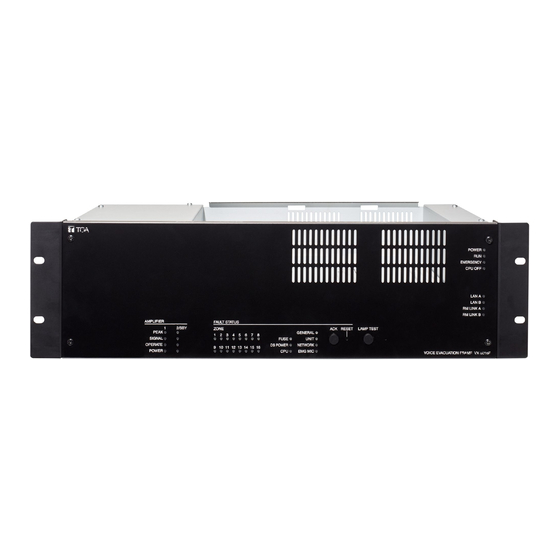
NOMENCLATURE AND FUNCTIONS Chapter 2 1. VX-3004F/3008F/VX-3016F VOICE EVACUATION FRAME VX-3004F, VX-3008F, and VX-3016F are collectively referred to as "VX-3000F" in this manual. • The VX-3000F is a unit designed to control the Voice evacuation announcements of the VX-3000 series voice evacuation system. • It has audio input terminals and can output the amplified audio signals to the speaker lines when the optional power amplifier modules are mounted. • Compatible with network, the system can be configured in distributed arrangement. [Front] VX-3004F Amplifier section Fault status section [Amplifier section] [Fault status section] 21 22 23 VX-3008F... - Page 11 NOMENCLATURE AND FUNCTIONS Chapter 2 VX-3016F Amplifier section Fault status section [Amplifier section] [Fault status section] 21 22 23 1. Power indicator (Green) 7. RS link A indicator (Green) Lights when the power is supplied. Lights when the RS link A connector (50) on Flashes in standby state.
- Page 12 NOMENCLATURE AND FUNCTIONS Chapter 2 11. Amplifier operate indicators (Green) 15. Power fault indicator (Yellow) The indicator corresponding to the module slot Lights or flashes when failures are detected in port will light or go off depending on the operation Power Supply Manager. state of the power amplifier when the power 16.
- Page 13 NOMENCLATURE AND FUNCTIONS Chapter 2 [Front panel detached] 26 27 29 30 31 24. Audio input volume controls [VX-3008F] Adjust the input volume of each input channel. • Switches 1 – 3 Rotating the control fully counterclockwise mutes Used to allocate speaker lines. (See 3-5.) the input sound source connected to that channel.
- Page 14 NOMENCLATURE AND FUNCTIONS Chapter 2 [Rear] VX-3004F 44 45 38 39 40 VX-3008F 35 33 35 33 VX-3016F 35 33 51 52...
- Page 15 NOMENCLATURE AND FUNCTIONS Chapter 2 32. DC power input terminal 40. MAC address Connect an optional DC power supply unit to This is the MAC address* for the unit. Since this terminal. Select the DC power supply source the relationship of each unit location to its MAC with consideration given to the current power address is established when setting the network consumption of the system the VX-3000F is to be...
- Page 16 VX-3000F in SS mode (with no B without using switching hubs. built-in Digital Power Amplifier) for zone number expansion by the VX-3008F or VX-3016F. * Contact your TOA dealer for more information on switching hubs. 52. Extension input connectors Notes Connect these connectors of the VX-3008F or • Be sure to connect both connectors of A and B.
-
Page 17: Vx-015Da/030Da/050Da Digital Power Amplifier Module
NOMENCLATURE AND FUNCTIONS Chapter 2 2. VX-015DA/030DA/050DA DIGITAL POwER AMPLIFIER MODULE • The VX-015DA, VX-030DA, and VX-050DA are Digital power amplifier modules used for the VX-3000 system. • They are module types with 1 channel of class-D digital power amplifier, which contributes to energy-saving and light weight design. • The VX-015DA, VX-030DA, and VX-050DA also feature standby mode to be set for reducing standby power consumption. • They require VX-3000F control unit and VX-3000DS power supply unit. Module lineup includes the following 3 models different in rated output. VX-015DA : 150 W VX-030DA : 300 W VX-050DA : 500 W [Front] [Rear]... -
Page 18: Rm-200Sf Fireman's Microphone
Adjusts the input sensitivity of the Hand-held This indicator will light yellow if the signal to the Microphone. VX-3000F or VX-3000F to which the RM-200SF is connected is interrupted for 5 seconds or more. 6. Microphone hanger Lights red when the unit is placed in reset state by Used to hold the unit's Hand-held Microphone. - Page 19 3000 Setting Software. (See the separate Setting 11. Reset switch Software Instructions, "RM Event Settings.") Used to reactivate the RM-200SF unit. 15. Microphone indicator (Green) Holding down both this switch and the R3 key of the Function keys (14) for 2 seconds or more...
- Page 20 LEVEL METER CPU OFF TERMINATION 20. DIP switch 23. Extension connector Used for setting the RM-200SF unit. Connect the cable extending from the RM-200SF • Switches 1 – 3 [UNIT ID] to this connector. (See 3-25.) Set the RM-200SF's device number (ID number). 24. Screw terminal block (See 3-9.)
-
Page 21: Rm-320F Fireman's Microphone Extension
NOMENCLATURE AND FUNCTIONS Chapter 2 4. RM-320F FIREMAN'S MICROPhONE EXTENSION Each connected RM-320F Extension unit adds 20 Function keys to the base RM-200SF. [Side] [Front] 1. Connection cable 5. Function keys (1 – 20) Used for connection to the RM-200SF or other Keys are numbered from 1 to 10 from upper left RM-320F. -
Page 22: Rm-300X Remote Microphone
NOMENCLATURE AND FUNCTIONS Chapter 2 5. RM-300X REMOTE MICROPhONE • The RM-300X Remote Microphone features 13 function keys, 1 covered key, 1 talk key, and the indicator lamps associated with these. Functions are assigned to the function keys using the VX-3000 Setting Software. • VX-3000 setting software permits desired functions to be assigned to individual Function keys (equipped with 2 LED indicators). • Connecting RM-210F Remote Microphone Extension (maximum 7) to the RM-300X expands the number of function keys and indicators in blocks of 10. • Up to 8 RM-300X Remote Microphones can be connected within a VX-3000F. - Page 23 NOMENCLATURE AND FUNCTIONS Chapter 2 7. Status indicators (Red/Yellow/Green) If the Talk key is set to "Lock" mode, then it must Light, flash, or go off depending on the current be pressed once to turn the microphone on at operation state of function keys, failure state or the beginning of a broadcast, then pressed again emergency state.
- Page 24 NOMENCLATURE AND FUNCTIONS Chapter 2 [Rear] 16. Power input terminal [DC POwER IN] Connect an optional AD-246 AC adapter to this terminal when extending cable length. (See 3-49.) Power is usually supplied to the RM-300X and RM-210F from the VX-3000F. 17.
-
Page 25: Rm-210F Remote Microphone Extension
NOMENCLATURE AND FUNCTIONS Chapter 2 6. RM-210F REMOTE MICROPhONE EXTENSION Each connected RM-210F Extension unit adds 10 Function keys to the base RM-300X. [Top] 1. Indication label insert slot The label can be printed using the VX-3000 Setting Software. (See the separate Setting Software Instructions, "PRINTING LABELS FOR REMOTE MICROPHONES.") 2. -
Page 26: Rm-200Rj Terminal Unit
NOMENCLATURE AND FUNCTIONS Chapter 2 7. RM-200RJ TERMINAL UNIT Convert the RJ45 connector into a screw terminal block. It is used to connect between a trunk cable (such as CPEV cable) and a feeder cable (such as LAN cable) in wiring a remote microphone. [Front] 1. -
Page 27: Sx-200El End Of Line Unit
NOMENCLATURE AND FUNCTIONS Chapter 2 8. SX-200EL END OF LINE UNIT Connected at the end of speaker line, the SX-200EL will detect abnormalities such as short-circuit, open-circuit, and ground fault of a speaker line. Note The SX-200EL is designed for exclusive use with the VX-3004F. 1. -
Page 28: Chapter 3 : Installation And Setting Procedures (Hardware)
Chapter 3 INSTALLATION AND SETTING PROCEDURES (hARDwARE) -
Page 29: Vx-015Da, Vx-030Da, And Vx-050Da Digital Power Amplifier Module
Note The speaker line failure detection functions are designed to perform on a 100-volt line of speaker. For the methods using a 70- or 50-volt line, please consult your TOA dealer. Output voltage selection switch VX-015DA/030DA/050DA side 1.2. Replacing the Blade Fuse When the blade fuse blew, replace it with new one following the procedures below. -
Page 30: Vx-3004F, Vx-3008F, And Vx-3016F Voice Evacuation Frame
INSTALLATION AND SETTING PROCEDURES (HARDWARE) Chapter 3 2. VX-3004F, VX-3008F, AND VX-3016F VOICE EVACUATION FRAME 2.1. Installing VX-015DA/030DA/050DA Digital Power Amplifier Module Multiple Digital power amplifier modules can be installed in each VX-3000F unit. The number of the Digital Power Amplifier modules to be installed and their mounting slot ports differ depending on the zone and amplifier module configurations. [Configuration and mounting slot port in the VX-3004F] Without standby amplifier With standby amplifier... - Page 31 INSTALLATION AND SETTING PROCEDURES (HARDWARE) Chapter 3 [Power amplifier installation procedure] There is a high voltage section inside the power amplifier's filter. Never wARNING insert your finger or metallic objects inside the unit. When attaching or detaching the connector, never touch the internal components other than connectors. Step 1. Shut off the power. Shut off the power when the power is supplied to the VX-3000F unit.
-
Page 32: The Zones Allocation Setting
INSTALLATION AND SETTING PROCEDURES (HARDWARE) Chapter 3 2.2. The Zones Allocation Setting For the VX-3008F and VX-3016F units, the preset relationship between broadcast zones and power amplifiers can be changed by the settings of the DIP switch inside the front panel. VX-3008F: You can perform the zone allocation settings for all-zone emergency broadcast at CPU off state. Note For normal broadcasts, use the VX-3000 Setting Software to perform this setting. - Page 33 INSTALLATION AND SETTING PROCEDURES (HARDWARE) Chapter 3 [DIP Switch setting] Step 1. Detach the front panel. Fixing screws for front panel Remove 4 fixing screws for front panel and detach the front panel. VX-3000F front WARNING There is a high voltage section inside the power amplifier's filter. Never insert your finger or metallic objects inside the unit.
-
Page 34: The Id Number Setting
INSTALLATION AND SETTING PROCEDURES (HARDWARE) Chapter 3 2.3. The ID Number Setting Notes • When setting the ID number for multiple VX-3000F units, assign different numbers to each unit. The ID number that can be used must not exceed the actual number of VX-3000F units set using the VX-3000 Setting Software. -
Page 35: Setting The Ip Address
INSTALLATION AND SETTING PROCEDURES (HARDWARE) Chapter 3 2.4. Setting the IP Address VX-3000F's IP address is automatically determined depending on the ID switch setting as follows when the switch 8 of the DIP switch inside the front panel is set to the ON position (default setting). IP address : 192.168.14.xx ("xx"... -
Page 36: Rm-200Sf And Rm-300X Microphones
INSTALLATION AND SETTING PROCEDURES (HARDWARE) Chapter 3 3. RM-200SF AND RM-300X MICROPhONES 3.1. The ID Number Settings (Switches 1 – 3 operation) Set ID numbers (device numbers) using switches 1 – 3 of the DIP switch located on the rear panel of the RM- 200SF and the side panel of the RM-300X. - Page 37 INSTALLATION AND SETTING PROCEDURES (HARDWARE) Chapter 3 Device number Switch 3 Switch 2 Switch 1 RM-200SF RM-300X (Default setting) 3-10...
-
Page 38: Adjusting Microphone Sensitivity
* When the microphone is in use, the indicator shows the output signal level. When the microphone is not in use, it shows the broadcast status. Step 1. Set switch 5 of the DIP switch on the rear panel of the RM-200SF to ON or switch 4 on the side panel of the RM-300X to ON. - Page 39 FIREMAN'S MICROPHONE Microphone volume control Microphone volume control Step 4. Set switch 5 of the RM-200SF to OFF or switch 4 of the RM-300X to OFF. Note Be sure to set both switches to OFF after adjusting the microphone input sensitivity.
-
Page 40: Cpu Off Function (All-Zone Emergency Broadcast) Settings
Broadcast key is being held down for 4 seconds or more. Whether or not this function is available can be set using switch 6 of the DIP switch on the rear panel of the RM-200SF or switch 5 on the side panel of the RM- 300X. -
Page 41: Termination Setting
INSTALLATION AND SETTING PROCEDURES (HARDWARE) Chapter 3 3.4. Termination Setting (RM-200SF: Switch 8 operation) Set the termination of the RM communication line. Normally set to OFF. DIP SWITCH UNIT ID COMMUNICATION LEVEL METER CPU OFF TERMINATION RM-200SF rear Terminal function... -
Page 42: Using An External Microphone (Rm-300X Only)
INSTALLATION AND SETTING PROCEDURES (HARDWARE) Chapter 3 3.5. Using an External Microphone (RM-300X Only) wARNING This change should only be performed by a qualified professional electrician. If users open the unit case or modify the unit, this may cause fire or electric shock. Changing the jumper settings on the RM-300X's circuit board causes an external microphone to be used. - Page 43 INSTALLATION AND SETTING PROCEDURES (HARDWARE) Chapter 3 Step 3. Replace the RM-300X's upper case. Note Note the types of screws when replacing the upper case (See Step 1.) [Plug for connection to the RM-300X's external input terminal] Connect the microphone's signal line to the tip and its shield line to the sleeve of the stereo mini plug or monaural mini plug.
-
Page 44: Using An Auxiliary Input (Rm-300X Only)
INSTALLATION AND SETTING PROCEDURES (HARDWARE) Chapter 3 3.6. Using an Auxiliary Input (RM-300X Only) wARNING This change should only be performed by a qualified professional electrician. If users open the unit case or modify the unit, this may cause fire or electric shock. Changing the jumper settings on the RM-300X's circuit board causes an auxiliary input to be used. - Page 45 INSTALLATION AND SETTING PROCEDURES (HARDWARE) Chapter 3 Step 3. Replace the RM-300X's upper case. Note Note the types of screws when replacing the upper case (See Step 1.) [Plug for connection to the RM-300X's external input terminal] Connect the sound source's signal line to the ring and its shield line to the sleeve of the stereo mini plug. [Stereo mini plug] Sleeve: Ground Ring: Signal line...
-
Page 46: Compressor Function Setting
Step 2. Set the jumper's position (JP301) on the circuit board attached to the front case as shown below. When the compressor function is used. RM-200SF inner circuit board (Factory-preset) JP301 When the compressor function is not used. JP301 JP301 Step 3. Replace the RM-200SF's rear plate. Note: Note the specific shapes of the different screws when replacing the rear plate. (See Step 1.) 3-19... - Page 47 INSTALLATION AND SETTING PROCEDURES (HARDWARE) Chapter 3 [RM-300X] Step 1. Unscrew 8 screws indicated by arrows in the figure at RM-300X bottom right, then detach the RM-300X's upper case. Note Note the types of screws. A: 3 x 8 tapping screw (white silver) ... 6 pieces B: 3 x 10 tapping screw (black) ....2 pieces Step 2.
-
Page 48: Microphone Fault Detection Function Setting (Rm-300X Only)
INSTALLATION AND SETTING PROCEDURES (HARDWARE) Chapter 3 3.8. Microphone Fault Detection Function Setting (RM-300X Only) wARNING This work should only be performed by a qualified professional electrician. If users open the unit case or modify the unit, this may cause fire or electric shock. The RM-300X is equipped with the microphone fault detection function, which can be set to OFF . -
Page 49: Installing The Rm-200Sf On A Wall
[Ferrite cable clamp attachment] The supplied ferrite clamp needs to be attached to the Link cable as illustrated below. As its mounting timing differs depending on the installation way of the RM-200SF, mount the clamp in the appropriate installation step. - Page 50 Chapter 3 [Installation] Step 1. Install the wall mount bracket unit supplied with the RM-200SF on the wall. 1-1. Installing directly on the wall Install the unit on the wall using 2 screws or more depending on the installation location.
- Page 51 Slide the Bracket A upward, then pull it toward you. Bracket A (3) Attach the Bracket B to the electrical box using 2 screws M3.5 x 20 supplied with the RM-200SF. Screw holes for mounting to the electrical box (2 places)
- Page 52 [when the RM-200SF is installed in a wall box] When the RM-200SF is installed in a wall box (prepare separately), the box should measure at least 300 mm wide x 315 mm high as illustrated below.
-
Page 53: Installing The Rm-320F On A Wall (Rm-200Sf Only)
Wall mount bracket unit .............. 1 (supplied with the RM-320F) Wall mounting screws 4 x 25 tapping screw for wooden wall ........2 (supplied with the RM-320F) Step 1. Install the wall mount bracket unit supplied with the RM-200SF on the wall. (See p. 3-23 3-24, Steps 1 and 2.) - Page 54 3-25, Steps 3 and 4.) Step 4. Connect the RM-320F's cable to the extension connector on the RM-200SF's side. Step 5. Install the RM-320F to its wall mount bracket sliding it in close contact with the RM-200SF as shown below.
-
Page 55: Rm-300X Extension With The Addition Of The Rm-210F
INSTALLATION AND SETTING PROCEDURES (HARDWARE) Chapter 3 3.11. RM-300X Extension with the Addition of the RM-210F (Installed on a Flat Surface) When adding an RM-210F Remote Microphone Extension to expand the RM-300X, use the RM-210F's Extension cable and included Linkage Bracket to link the 2 microphones. Up to 7 RM-210Fs can be conncted to an RM-300X. -
Page 56: Installing The Rm-300X On A Wall
INSTALLATION AND SETTING PROCEDURES (HARDWARE) Chapter 3 3.12. Installing the RM-300X on a wall [Mounting hardware] To mount the RM-300X on the wall, the following parts are required. Wall mounting bracket for the RM-300X (model WB-RM200) ..1 (option) M3.5 x 20 screw for electrical box ..........2 (supplied with the WB-RM200) 4 x 25 tapping screw for wooden wall ......... -
Page 57: Installing The Rm-210F On A Wall (Rm-300X Only)
INSTALLATION AND SETTING PROCEDURES (HARDWARE) Chapter 3 3.13. Installing the RM-210F on a wall (RM-300X Only) [Mounting hardware] To mount the RM-210F on the wall, the following parts are required. Wall mounting bracket for the RM-210F (model WB-RM 200) ..1 (option) M3.5 x 20 screw for electrical box .......... - Page 58 INSTALLATION AND SETTING PROCEDURES (HARDWARE) Chapter 3 Step 3. Using the extension cable supplied with the RM-210F, connect the RM-300X's side EXTENSION connector to the RM-210F's side EXTENSION connector. Step 4. Hook the bottom surface of the RM-210F onto the WB-RM200. Extension cable (supplied with the RM-210F) RM-210F...
-
Page 59: Creating Remote Microphone Name Labels
Chapter 3 3.14. Creating Remote Microphone Name Labels Using the VX-3000 Setting Software function, assigned names of preset RM-200SF, RM-320F, RM-300X, and RM-210F Function keys can be printed out. Once printed, cut out the printed names with scissors to use them as corresponding name labels. - Page 60 INSTALLATION AND SETTING PROCEDURES (HARDWARE) Chapter 3 3.14.2. If the name label is not printed correctly The name label created using the VX-3000 Setting Software may not be printed in correct size depending on the configuration environment of your PC. In such cases, try one of the methods described below. (1) Preparation by hand Copy the "Pattern paper for hand writing" on the next page. After writing a name, cut out the pattern paper aligning it with the cutting guidelines.
- Page 61 INSTALLATION AND SETTING PROCEDURES (HARDWARE) Chapter 3 3.14.4. Pattern paper for hand writing Name label A Name label B Name label C Cutting guideline Shown in actual size 3-34...
-
Page 62: Rack Mounting
INSTALLATION AND SETTING PROCEDURES (HARDWARE) Chapter 3 3.15. Rack Mounting CAUTION Rack-mounting screws are not supplied with the unit. Prepare them that are appropriate for the equipment rack. Failure to do so may cause personal injury. Rack-mounting screw VX-3000F Rack-mounting screw [Perforated panel mounting] Be sure to mount the PF-013B (1U) to the locations described below. -
Page 63: Connections
INSTALLATION AND SETTING PROCEDURES (HARDWARE) Chapter 3 4. CONNECTIONS 4.1. Removable Terminal Plug Connection Notes • Do not use a micro screwdriver. Sufficient torque is not given to the screws when tightening them, and connections may not be secured. • Avoid soldering stranded or shielded cable, as contact resistance may increase when the cable is tightened and the solder is crushed, possibly resulting in an excessive rise in joint temperatures. -
Page 64: Input Equipment Connections
2 in total, and 1 to a single channel of RS link. (4) When connecting the RM-200SF or the RM-300X for emergency use directly to each VX-3000F's RS link, make its distance shortest compared to other remote microphones. - Page 65 INSTALLATION AND SETTING PROCEDURES (HARDWARE) Chapter 3 • When connecting 2 or more remote microphones to a RS LINK, make branch wiring using the RM-200RJ Terminal Unit or the Wall mount bracket unit supplied with the RM-200SF. (When connecting 2 or more remote microphones: Example 1) RM-200SF RM-200RJ RM-300X VX-3000F RM-200RJ RM-300X RM-200RJ RM-300X (When connecting 2 or more remote microphones: Example 2)
- Page 66 The number of remote microphones connectable in a system is as follows. • Up to 2 RM-200SFs and up to 6 RM-300Xs (8 units in total) can be connected to the VX-3000F. • Up to 4 RM-320Fs can be connected to the RM-200SF, and up to 7 RM-210Fs to the RM-300X. The method of power supply to the remote microphones differs depending on the system application and configuration, and also type of remote microphone. In a system configuration, the allowable number of the microphones connected to the VX-3000F may be limited.
- Page 67 Chapter 3 4.2.3. RM-200SF connection Connect the RM-200SF to either of the RS LINK A or RS LINK B connector of the VX-3000F. The maximum cable distance depends on how power is supplied. [when power is supplied from the VX-3000F used with the VX-3000DS]...
- Page 68 Chapter 3 • When the VX-3000DS is operating on AC power The following table shows the maximum cable distance when STP Category 5 straight cable (with RJ45 connectors) is used. No. of extension RM-200SF RM-200SF + RM-200SF + RM-200SF + RM-200SF + units alone RM-320F x 1...
- Page 69 (Operation range: 14 – 28 V DC) When a STP category 5 straight cable or over 4-pair shielded CPEV cable is used as communication cable (excluding power line) between the RM-200SF and the VX-3000F, the maximum cable distance in a system is 1200 m in total.
- Page 70 (–) VX-3000DS’ DC POWER OUT terminal When a STP Category 5 straight cable is used as communication cable (excluding power line) between the RM-200SF and the VX-3000F, the maximum cable distance in a system is 1200 m in total. 3-43...
- Page 71 INSTALLATION AND SETTING PROCEDURES (HARDWARE) Chapter 3 • When the VX-3000DS is operating on AC power The maximum distance of power cable between the RM-200SF and the VX-3000DS is as follows. The following table shows the maximum cable distance when STP Category 5 straight cable (with RJ45 connectors) is used.
- Page 72 INSTALLATION AND SETTING PROCEDURES (HARDWARE) Chapter 3 4.2.4. RM-300X connection Connect the RM-300X to either of the RS LINK A or RS LINK B connector of the VX-3000F. The maximum cable distance depends on how power is supplied. RM-300X rear Connection cable (with RJ45 connectors) To VX-3000F...
- Page 73 INSTALLATION AND SETTING PROCEDURES (HARDWARE) Chapter 3 • When the VX-3000DS is operating on battery The following table shows the maximum cable distance when STP Category 5 straight cable (with RJ45 connectors) is used. No. of extension RM-300X + RM-300X + RM-300X + RM-300X alone units RM-210F x 1 RM-210F x 2 RM-210F x 3...
- Page 74 INSTALLATION AND SETTING PROCEDURES (HARDWARE) Chapter 3 Tips • When using a shielded CPEV cable, it is recommended to use an optional RM-200RJ Terminal Unit that serves wiring conversion between the CPEV cable and STP Category 5 straight cable (with RJ45 connectors). Connect the CPEV cable between the same terminals of both RM-200RJ units pairing cables 1 with 2, 4 with 5, 3 with 6, and 7 with 8 as shown below.
- Page 75 INSTALLATION AND SETTING PROCEDURES (HARDWARE) Chapter 3 • When using a shielded CPEV cable but not the RM-200RJ, connect the cable to STP Category 5 straight cable (with RJ45 connectors) as follows. Pair 1 with 2, 3 with 6, 4 with 5, and 7 with 8. To VX-3000F To RM-300X Over 4-pair shielded CPEV cable (main cable) RJ45 connector RJ45 connector pin No.
- Page 76 INSTALLATION AND SETTING PROCEDURES (HARDWARE) Chapter 3 [when power is supplied from the AC adapter] VX-3000F RM-300X AC adapter When supplying power to the RM-300X from the optional AD-246 AC Adapter using an STP category 5 straight cable or over 4-pair shielded CPEV cable, the maximum length of connection cable (excluding power line) is 1200 m regardless of the type of cable and the number of remote microphone extension units.
- Page 77 INSTALLATION AND SETTING PROCEDURES (HARDWARE) Chapter 3 [when power is supplied from the VX-3000DS] VX-3000F RM-300X VX-3000DS AC power Battery VX-3000F RM-200RJ STP Category 5 straight cable Shield (with RJ45 connectors) VX-3000DS’s DC Power out terminal RM-300X rear Over 4-pair shielded RM-200RJ CPEV cable (main cable) STP Category 5 straight cable...
- Page 78 INSTALLATION AND SETTING PROCEDURES (HARDWARE) Chapter 3 • When the VX-3000DS is operating on AC power The maximum distance of power cable between the RM-300X and the VX-3000DS is as follows. The following table shows the maximum cable distance when STP Category 5 straight cable (with RJ45 connectors) is used.
- Page 79 INSTALLATION AND SETTING PROCEDURES (HARDWARE) Chapter 3 4.2.5. Connecting other input equipment Connect microphones or other sound sources with line outputs using 2-core shielded cables. Four input channels (1 through 4) are provided for the AUDIO INPUT. Use the VX-3000 Setting Software to set their volume, purpose, and type, etc. (See the separate Setting Software Instructions, "Unit configuration setting.") VX-3000F...
-
Page 80: Speaker Connection
INSTALLATION AND SETTING PROCEDURES (HARDWARE) Chapter 3 4.3. Speaker Connection Connect speakers to the speaker output terminal. Following 3 types of wiring systems are available: 2-wire system where no attenuator is connected, and 3-wire and 4-wire systems where attenuators are connected. Failure detection is available if the EOL unit is connected. - Page 81 INSTALLATION AND SETTING PROCEDURES (HARDWARE) Chapter 3 4.3.3. 4-wire system connection Two types of attenuators are connectable to this unit, one to be bypassed when 24 V DC is applied to the attenuator, and the other to be bypassed when the 24 V DC being normally applied to is cut off (in no voltage mode).
- Page 82 INSTALLATION AND SETTING PROCEDURES (HARDWARE) Chapter 3 4.3.4. End of line Speaker line failure can be detected with greater accuracy when the end of line units are connected. Use the SX-200EL for the VX-3004F unit and the VM-300SV for the VX-3008F and VX-3016F units. [Example 1] The figure below shows a connection example to connect the SX-200EL to the speaker line.
-
Page 83: Control Output Terminal Connections
INSTALLATION AND SETTING PROCEDURES (HARDWARE) Chapter 3 4.4. Control Output Terminal Connections These terminals provide control outputs of relay contact type. Control signals (make contact) are output in synchronization with unit operation. VX-3000F The RJ45's pin arrangement and pin functions are shown below. [CONTROL OUT 1] Pin1 Pin2... -
Page 84: Control Input Terminal Connections
INSTALLATION AND SETTING PROCEDURES (HARDWARE) Chapter 3 4.5. Control Input Terminal Connections The control input terminals are non-voltage contact inputs. Cable disconnection and short-circuit can be detected using these input terminals. Set the applications, signal input type, and failure detection using the VX-3000 Setting Software. (See the separate Setting Software Instructions, "SURVEILLANCE SETTINGS,"... -
Page 85: Emergency Control Input Terminal Connections
INSTALLATION AND SETTING PROCEDURES (HARDWARE) Chapter 3 4.6. Emergency Control Input Terminal Connections The Emergency control input terminals are voltage inputs. Cable disconnection and short-circuit can be detected using these input terminals. Use the VX-3000 Setting Software to set the applications and signal input type. (See the separate Setting Software Instructions, "SURVEILLANCE SETTINGS,"... -
Page 86: Vx-3000F Connection
INSTALLATION AND SETTING PROCEDURES (HARDWARE) Chapter 3 5. VX-3000F CONNECTION 5.1. LAN Link Connector Connections Connect the LAN link connectors of all VX-3000F units within the system to each other via switching hubs. Connect each of LAN link connectors A and B to the same switching hub or different switching hubs connected in star configuration. - Page 87 INSTALLATION AND SETTING PROCEDURES (HARDWARE) Chapter 3 [Connection example 4: Non-redundant configuration of non-RSTP-compliant switching hubs] VX-3000F LAN link A, B SW-HUB SW-HUB SW-HUB SW-HUB LAN link A, B VX-3000F VX-3000F VX-3000F 3-60...
- Page 88 To other switching hub switching hub VX-3000F Switching hub (A-1) Switching hub (B-1) VX-3000F Main line Switching hub (B-2) Switching hub (A-2) VX-3000F : LAN Link : Control line Note: Contact your TOA dealer for more information on switching hubs. 3-61...
- Page 89 (For details, see the separate Setting Software Instructions, "EVENT SETTINGS.") VX-3000F Switching hub VX-3000F Switching hub VX-3000F VX-3000F Switching hub VX-3000F VX-3000F Switching hub : LAN link : Control line Note: Contact your TOA dealer for more information on switching hubs. 3-62...
- Page 90 INSTALLATION AND SETTING PROCEDURES (HARDWARE) Chapter 3 5.1.3. Redundant configuration when no switching hubs are used In the connection example below, both LAN link A and B terminals of each unit are connected to another VX- 3000F. Notes • Up to 7-level cascade is allowed for switching hub connections. • Up to 8 VX-3000Fs can be connected.
- Page 91 In the connection example below, both LAN Link A and B terminals of each unit are connected to the same switching hub. Notes • Up to 7-level cascade is allowed for switching hub connections. • After connection completion, reactivate the VX-3000F by pressing the Reset key on its front panel. VX-3000F VX-3000F Switching hub VX-3000F VX-3000F Switching hub VX-3000F Note: Contact your TOA dealer for more information on switching hubs. 3-64...
-
Page 92: Sharing Standby Amplifier
INSTALLATION AND SETTING PROCEDURES (HARDWARE) Chapter 3 5.2. Sharing Standby Amplifier Up to 8 VX-3000F units can share a single standby amplifier installed in any one of them. The standby amplifier must have the rated power output equal to or larger than the maximum output of the power amplifiers which share the standby amplifier. Connect the standby amplifier output connector of the VX-3000F with the built-in standby amplifier to the next VX-3000F's standby amplifier input connector. Similarly, make standby amplifier output/input connections for other units one after another. VX-3000F (With standby amplifier installed) VX-3000F (With no standby amplifier installed) Max. 8 pcs VX-3000F (With no standby amplifier installed) 3-65... -
Page 93: Speaker Selector Extension
INSTALLATION AND SETTING PROCEDURES (HARDWARE) Chapter 3 5.3. Speaker Selector Extension The VX-3008F or VX-3016F can be used as speaker selector that extends the number of speaker lines without having a built-in power amplifier. Up to 3 VX-3000F units for broadcast zone extension use can be connected to a single VX-3008F or VX-3016F. Connect the extension output connector of the VX-3008F or the VX-3016F with the built-in amplifier module to the next VX-3008F's or VX-3016F's extension input connector. -
Page 94: Analog Link Terminal Connections
Connecting all VX-3000F units within the system via Analog link connectors permits all-zone emergency broadcast to be initiated from the RM-300X Remote Microphone or the RM-200SF Fireman's Microphone through the connected lines if normal broadcasts cannot be made due to equipment failures. (See 3-13.) -
Page 95: Speaker Line Initial Setting
INSTALLATION AND SETTING PROCEDURES (HARDWARE) Chapter 3 6. SPEAKER LINE INITIAL SETTING To perform Speaker Line Surveillance, be sure to make the initial settings for the VX-3000F as follows after connection completion of the VX-3000 system. 6.1. Setting Items [Initial impedance value setting] The VX-3000F determines whether the speaker line is open or shorted using this initial value as reference value (normal impedance value). -
Page 96: Setting Procedures
INSTALLATION AND SETTING PROCEDURES (HARDWARE) Chapter 3 6.3. Setting Procedures 6.3.1. Setting an initial impedance value Notes • When attenuators are connected to the speaker line, set their attenuation level to their maximum position. Otherwise, the initial impedance value cannot be set correctly. • Be sure to perform this setting after completion of connection work. • Be sure to reset the initial impedance value if any wiring or connection has been changed after completion of the setting. Step 1. Detach the front panel. Fixing screws for front panel Remove 4 fixing screws for front panel and detach the front panel. - Page 97 INSTALLATION AND SETTING PROCEDURES (HARDWARE) Chapter 3 6.3.2. Adjusting the speaker line's OPEN sensitivity Open sensitivity is expressed as the ratio to the initial value (defined as 100 %) and can be adjusted in the range of 101 % to 800 %. It is set to "200" for all the channels by default. Perform this setting using the VX-3000 Setting Software. Note Moving the setting closer to 101 % increases the OPEN sensitivity, and thus improves the accuracy of "OPEN"...
-
Page 98: Chapter 4 : Appendix
Chapter 4 APPENDIX... -
Page 99: The Firmware Version Confirmation
APPENDIX Chapter 4 1. ThE FIRMwARE VERSION CONFIRMATION You can confirm the firmware version with the front-mounted indicators by setting the DIP switch inside the VX-3000F's front panel. [Front-mounted indicators] This figure shows VX-3004F. Step 1. Detach the front panel. Remove 4 fixing screws for front panel and detach the front panel. Fixing screws for front panel VX-3000F front WARNING There is a high voltage section inside the power amplifier's filter. - Page 100 APPENDIX Chapter 4 [how to confirm the firmware version] • Firmware version indication The VX-3000's firmware version is expressed as shown in the following example. Here, the individual numbers are denoted by (A) to (E). Example : V e r . 1 . 2 3 . 4 5 (A) (B)(C) (D)(E) • Each digit is defined by the indicator status of from (A) to (E) as shown below. [VX-3004F] (A) (B) (C) (D) [VX-3008F]...
-
Page 101: Specifications
100BASE-TX Network Protocol: TCP, UDP, ARP, ICMP, RTP, IGMP, FTP, HTTP Spanning tree Protocol: RSTP Audio Transmission System: TOA Packet Audio Audio Encoding Method: Audio Sampling Frequency: 48 kHz Audio Quantifying Bit Number: 16 bits Connection Device: other VX-3004F, VX-3008F, VX-3016F, Switching HUB... - Page 102 APPENDIX Chapter 4 Control Output 1, 2 General outputs : 8 with CONTROL OUTPUT 1 Exclusive outputs : 3 with CONTROL OUTPUT 2 GENERAL FAULT, CPU FAULT, CPU OFF No-voltage make contact, electrical contact output, control current: 10 mA Connector: RJ45 connector Connection Cable: Shielded Category 5 twisted pair cable (CAT5-STP)
-
Page 103: Vx-3008F Voice Evacuation Frame 8Ss
100BASE-TX Network Protocol: TCP, UDP, ARP, ICMP, RTP, IGMP, FTP, HTTP Spanning tree Protocol: RSTP Audio Transmission System: TOA Packet Audio Audio Encoding Method: Audio Sampling Frequency: 48 kHz Audio Quantifying Bit Number: 16 bits Connection Device: VX-3004F, other VX-3008F, VX-3016F, Switching HUB... - Page 104 APPENDIX Chapter 4 ATT/Control Output 8 outputs, no-voltage make contact, relay contact (NC, NO, C), control current: 2 mA to 5 A Connector: Removable terminal block (12 pins) ...2 Audio Input 1, 2, 3, 4 4 inputs Sensitivity: LINE: −20 dB* , MIC: −60 dB* LINE/MIC (changeable with setting software) Gain Control: Volume adjustable with volume control (internal front panel)
-
Page 105: Vx-3016F Voice Evacuation Frame 16Ss
100BASE-TX Network Protocol: TCP, UDP, ARP, ICMP, RTP, IGMP, FTP, HTTP Spanning tree Protocol: RSTP Audio Transmission System: TOA Packet Audio Audio Encoding Method: Audio Sampling Frequency: 48 kHz Audio Quantifying Bit Number: 16 bits Connection Device: VX-3004F, VX-3008F, other VX-3016F, Switching HUB... - Page 106 APPENDIX Chapter 4 ATT/Control Output 16 outputs, no-voltage make contact, relay contact (NC, NO, C), control current: 2 mA to 5 A Connector: Removable terminal block (12 pins) ...4 Audio Input 1, 2, 3, 4 4 inputs Sensitivity: LINE: −20 dB* , MIC: −60 dB* LINE/MIC (changeable with setting software) Gain Control: Volume adjustable with volume control (internal front panel)
-
Page 107: Vx-015Da Digital Power Amplifier Module 150 W
APPENDIX Chapter 4 2.4. VX-015DA Digital Power Amplifier Module 150 w Power Source 31 V DC (operating range: 20 to 33 V DC) DC power in: M4 screw terminal, distance between barriers: 11 mm (0.43") Amplification System Class D Power Consumption 40 W at 31 V DC Rated Output Power 150 W (at 100 V line and min. -
Page 108: Vx-030Da Digital Power Amplifier Module 300 W
APPENDIX Chapter 4 2.5. VX-030DA Digital Power Amplifier Module 300 w Power Source 31 V DC (operating range: 20 to 33 V DC) DC power in: M4 screw terminal, distance between barriers: 11 mm (0.43") Amplification System Class D Power Consumption 65 W at 31 V DC Rated Output Power 300 W (at 100 V line and min. -
Page 109: Vx-050Da Digital Power Amplifier Module 500 W
APPENDIX Chapter 4 2.6. VX-050DA Digital Power Amplifier Module 500 w Power Source 31 V DC (operating range: 20 to 33 V DC) DC power in: M4 screw terminal, distance between barriers: 11 mm (0.43") Amplification System Class D Power Consumption 100 W at 31 V DC Rated Output Power 500 W (at 100 V line and min. -
Page 110: Rm-200Sf Fireman's Microphone
APPENDIX Chapter 4 2.7. RM-200SF Fireman's Microphone Power Source 24 V DC (operating range: 15 – 40 V DC, supplied from the VX-3000 system.) Current Consumption 240 mA or less Audio Output 0 dB*, transformer-balanced Distortion 1% or less Frequency Response 200 Hz –... -
Page 111: Rm-320F Fireman's Microphone Extension
APPENDIX Chapter 4 2.8. RM-320F Fireman's Microphone Extension Current Consumption 180 mA max. (in terms of RM-300MF) Connection Connection to RM-200SF by dedicated cable Operation Operation Function Keys ...20 Indicator Status indicator ...20, Selection indicator ...20 Finish ABS resin, blueish gray (PANTONE 538 or its equivalent) Dimensions 175 (w) x 215 (h) x 70 (d) mm (6.89"... -
Page 112: Rm-300X Remote Microphone
APPENDIX Chapter 4 2.9. RM-300X Remote Microphone Power Source 24 V DC (operating range: 15 to 40 V DC, supplied from the voice evacuation frame) or DC input power supply connector (when the optional AD-246 power supply unit used). Usable DC power supply plug: 5.5 mm (0.22") outer diameter, 2.1 mm (0.08") inner diameter, 9.5 mm (0.37") long, and non-polarity type. -
Page 113: Rm-210F Remote Microphone Extension
APPENDIX Chapter 4 2.10. RM-210F Remote Microphone Extension Power Source Supplied from the optional RM-300X AC Power Consumption 2.4 W (including power supply loss of the Emergency power panel) 0.4 W (standby, including power supply loss of the Emergency power panel) Current Consumption 80 mA or less (increase in power input at the optional RM-300X) Operation... -
Page 114: Vm-300Sv End Of Line Unit
20 g (0.04 lb) Note: The design and specifications are subject to change without notice for improvement. Traceability Information for Europe Manufacturer: Authorized representative: TOA Corporation TOA Electronics Europe GmbH 7-2-1, Minatojima-Nakamachi, Chuo-ku, Kobe, Hyogo, Suederstrasse 282, 20537 Hamburg, Japan Germany URL: http://www.toa.jp/...
Need help?
Do you have a question about the RM-200SF and is the answer not in the manual?
Questions and answers