
Related Manuals for Stulz CyberAir 3PRO CW2


Summary of Contents for Stulz CyberAir 3PRO CW2
- Page 1 CyberAir 3PRO CW2 Original instructions Precision Air Conditioning Units ASD/ASU series Index G18D 400 V / 3 Ph+N+PE / 50 Hz Issue 6.2017...
- Page 2 CY B E R A I R 3 P R O C W 2 O R I G I N A L I N S T R U C T I O N S A B O U T S T U L Z Since it was founded in 1947, the STULZ company has evolved into one of the world’s leading system suppliers of air-conditioning technology.
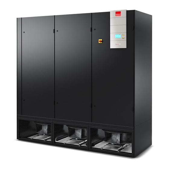
- Page 3 CyberAir 3PRO CW2 is the result of consistent further development of our thoroughly successful CyberAir 3 series. With our CyberAir 3PRO CW2 units, STULZ is introducing a new series of units offering maximum potential savings. The units control the climate in the data center with the utmost precision, reliability and energy efficiency.
- Page 4 CY B E R A I R 3 P R O C W 2 O R I G I N A L I N S T R U C T I O N S EN/06.2017/G18D © STULZ GmbH – all rights reserved...
-
Page 5: Table Of Contents
7.4 Water circuit .......................... 34 7.5 Unit housing .......................... 34 8. Malfunction ...................... 35 9. Dismantling and disposal ................36 10. Contents of the CE Declaration of Conformity ..........37 11. Options Subject to technical modifications. © STULZ GmbH – all rights reserved EN/06.2017/G18D... -
Page 6: Safety
They must therefore be read and complied with by the fitter and the responsible trained staff/operators before assembly and commissioning. They must be permanently available at the place where the system is used. danger • Works have to be carried out by competent staff only. • Safety devices may not be bypassed. EN/06.2017/G18A-D © STULZ GmbH – all rights reserved... -
Page 7: Duties Of The Operator
The operator is responsible for the execution. The operator must ensure that all maintenance, inspection and assembly work is carried out by authorised and qualified specialist staff who have made an in-depth study of the operating instructions. independent conversion and manufacture of replacement parts The system may only be converted or modified after consultation with STULZ. Original replacement parts and replacement parts/accessories authorised by STULZ are an aid to safety. © STULZ GmbH – all rights reserved EN/06.2017/G18A-D... -
Page 8: Transport / Storage
Do not stay under suspended loads! The Stulz A/C units can be moved by lifting devices with belts or ropes. • fix the belts or ropes at the pallet, • p rotect the upper unit edges by wooden laths or metal brackets in such a way that they could not be caved notice risk of distorting the frame Never move the unit on rollers and never transport it on a fork lift without pallet. You can move the unit still packaged on the pallet with a fork lift. • take care that the centre of gravity is within the fork surface. • take care that the unit is in an upright position at the transport. EN/06.2017/G18A-D © STULZ GmbH – all rights reserved... -
Page 9: Storage
3 P r O c W O r i g i n a l i n S T r U c T i O n S 2.3 Storage If you put the unit into intermediate storage before the installation, the following measures have to be carried out to protect the unit from damage and corrosion: • t he storage point must not be exposed to direct sunlight. Observe the storage conditions in the chapter “Application limits“. • store the unit packaged to avoid the risk of corrosion. • m ake sure that the water connections are provided with protective hoods. © STULZ GmbH – all rights reserved EN/06.2017/G18A-D... -
Page 10: Description
Page code EN/06.2017/G18D Date of issue Index number month/year Language: Manufacturing base: EN = English G = Germany DE = German C = China FR = french I = Italy ES = spanish EN/06.2017/G18D © STULZ GmbH – all rights reserved... -
Page 11: Intended Use
19 units from one unit. These units can be installed separately with a maximum control line length of 1000 m. Downflow unit Upflow unit © STULZ GmbH – all rights reserved EN/06.2017/G18D... -
Page 12: Technical Data
Lower limit: 5 °C dew point different from the standard voltage (400V/3Ph/50 Hz). In Upper limit: 60 % r. h. and 16 °C dew point this case, see the technical data by the help of the „Stulz Select“ planning tool. Storage conditions: The unit design, the external dimensions, the weight, the Temperature [°C]:... -
Page 13: Technical Data - Asd
Schalldruckpegel Sound pressure level Baugröße Cabinet size Gewicht Weight For electrical data, (fan power consumption) see e-data sheet. The electrical power consumption of the fans must be added to the room load. © STULZ GmbH – all rights reserved EN/06.2017/G18D... -
Page 14: Dimensional Drawings
3 P r O c w 2 O r i g i n a l i n s t r u c t i O n s 4.4 Dimensional drawings Cabinet size 1 Cabinet size 2 Side view (for all sizes) 890/980* 1400 935/1025* * for size 7 Cabinet size 3 Cabinet size 4 2200 1750 2200 EN/06.2017/G18D © STULZ GmbH – all rights reserved... - Page 15 3 P r O c w 2 O r i g i n a l i n s t r u c t i O n s Cabinet size 5 Projecting main switch Main switch 2550 Cabinet size 7 3110 © STULZ GmbH – all rights reserved EN/06.2017/G18D...
-
Page 16: Installation
The A/C unit must be accessible from the front and requires space on the left and right side for the supply connections. Electrical connection Supply connections for: - humidifier (optional) Clearance for chilled water connection Maintenance clearance min 0,5 m EN/06.2017/G18D © STULZ GmbH – all rights reserved... -
Page 17: Positioning The Unit
• drive the unit by the mounting aids to the installation site. • drop the unit, loosen the belts and pull away the mounting aids. A/C unit transport with mounting aids Mounting aids © STULZ GmbH – all rights reserved EN/06.2017/G18D... - Page 18 • drive the unit by the mounting aids to the installation site. • drop the unit, loosen the belts and pull away the mounting aids. notICe Place the male triangular wrench in a visible location in the immediate vicinity of the A/C unit. EN/06.2017/G18D © STULZ GmbH – all rights reserved...
-
Page 19: Water Piping Connection
• screw the lines of the external system to the lines of the unit respecting the designation at the unit (inlet/ outlet). • insulate the water pipes with the diffusion tight insulating material, to prevent the introduction of ambient air heat and the formation of condensate at the pipes. © STULZ GmbH – all rights reserved EN/06.2017/G18D... -
Page 20: Pipe Entrance Area - Downflow Version
7 - chilled water inlet 2 ø bauseits ø by client 3 - power supply 8 - chilled water outlet 2 4 - condensate drain Außengewinde external thread inch Zoll 1 1/4 5 - control lines EN/06.2017/G18D © STULZ GmbH – all rights reserved... - Page 21 2 - chilled water outlet 1 8 - chilled water outlet 2 3 - power supply ø bauseits ø by client 4 - condensate drain Außengewinde external thread inch Zoll 1 1/2 5 - control lines © STULZ GmbH – all rights reserved EN/06.2017/G18D...
- Page 22 3 P r O c w 2 O r i g i n a l i n s t r u c t i O n s EN/06.2017/G18D © STULZ GmbH – all rights reserved...
- Page 23 3 P r O c w 2 O r i g i n a l i n s t r u c t i O n s © STULZ GmbH – all rights reserved EN/06.2017/G18D...
-
Page 24: Pipe Entrance Area - Upflow Units
For the routing of the piping into the unit there are several possibilities. The most favourable openings are those which are recommended in the tables. The lines for the power supply, the humidifier connections and the condensate drain can be routed through the remaining openings as desired. EN/06.2017/G18D © STULZ GmbH – all rights reserved... -
Page 25: Condensate Drain Connection
Connect the condensate water drains to the local waste water system. unit limit InForMAtIon Comply with the regulations of the local water sup- ply authority. possible installation at the custo- mer side: funnel © STULZ GmbH – all rights reserved EN/06.2017/G18D... -
Page 26: Electrical Connection
Do not touch electronical components, without taking care of protective ESD measures. Electronical components: - C7000 IO controller (1) - Humidifier board (option) EN/06.2017/G18D © STULZ GmbH – all rights reserved... - Page 27 Connection of control lines (optional) If the A/C unit shall be connected to other Stulz units by the IO bus, to a BMS or contains opional extensions as louvers, you must route control lines and connect them in the electric box of the A/C unit.
- Page 28 3 P r O c w 2 O r i g i n a l i n s t r u c t i O n s upflow units Cabinet size 1 Cabinet sizes 2 - 7 EN/06.2017/G18D © STULZ GmbH – all rights reserved...
-
Page 29: Commissioning
Lethal dose: 0,4 g ethylene glycol/kg body weight, severe intoxication: already at 0,1 ml/kg. Glycol is absorbed through the skin. Therefore immediately change clothing soaked with glycol. Wear protective gloves made of rubber. © STULZ GmbH – all rights reserved EN/06.2017/G18D... -
Page 30: Control Of The Electrical Box
• switch on the A/C unit at the master switch. The controller is now supplied with power, so you can use it for adjustments. • make sure that the heat rejecting system (chiller) is operating. EN/06.2017/G18D © STULZ GmbH – all rights reserved... - Page 31 • connect a notebook at the service port X15 on the C7000IOC board, to carry out possible configurations (setting the setpoint). • shut the electrical box door. • start the A/C unit by pressing the Start/Stop-key on the controller. Controller C7000Advanced Terminal, Start/stop-key © STULZ GmbH – all rights reserved EN/06.2017/G18D...
-
Page 32: Maintenance
• carry out work on the system only when it is shut down. • switch off the A/C unit at the controller and at the master switch. • display a „DO NOT SWITCH ON“ warning sign. • switch off power conducting cables to the unit and secure them against being switched on again. • check to ensure that they are in the de-energized state. 7.2 Maintenance intervals Maintenance interval Component quarterly half-yearly yearly Air circuit Heat exchanger Air filter Water circuit Tightness Unit housing Electrical box Unit interior EN/06.2017/G18D © STULZ GmbH – all rights reserved... -
Page 33: Air Circuit
NotiCe Do not distort the fins while cleaning, this also increases the air resistance. • c lean the heat exchanger by pressurized air by blowing it opposite to the normal air flow direction along the fins. WArNiNg risk of injury by burns and rotation The electronics housing can get hot. The fans have an operation delay after the unit is stopped ! The bearings of the fans are lifetime lubricated and do not need maintenance. Air filter A filter monitor controls the state of the filter. As soon as the pressure loss exceeds an adjustable value, a filter alarm via the controller is released. The controller can be configured such as to compensate the pressure loss by a higher fan speed, however you should not wait too long for exchanging the filter. The filters can be accessed by the front doors, depending on the cabinet size the number of filter elements varies. The clogged filter elements can not be cleaned with pressurized air, as the filter structure would be destroyed otherwise. When you re-install the filter elements after the exchange, take care that the side with the coloured mark (dirt side) is turned away from the heat exchanger. © STULZ GmbH – all rights reserved EN/06.2017/G18D... -
Page 34: Water Circuit
PE after disconnection. electrical box • c heck the connection terminals for tight fixation when the unit is installed and once again after an operation time of 30 days. Unit interior Clean pipes simplify the search for leaks. • clean the unit‘s inside with a vacuum cleaner. Vibrations of pipes and circuit components can result in leaks. • check the pipes for a tight seat. Condensing air humidity on cold water pipes means a loss of cooling capacity. • check the insulation of the water piping. EN/06.2017/G18D © STULZ GmbH – all rights reserved... -
Page 35: Malfunction
2. sensor cable defective. Check cable on continuity. 3. sensor defective. Check measured value with external thermo- meter, hygrostat, pressure gauge. Depending on the option configured in the controller further alarm messages exist. # stands for a number in case of several components of the same kind. © STULZ GmbH – all rights reserved EN/06.2017/G18D... -
Page 36: Dismantling And Disposal
• d isconnect the unit from the external water circuit by closing the shut-off valves and drain the water circuit of the unit. • disconnect the depressurized chilled water pipes of the unit from the external system. • m ove the unit, as described in the chapter „transport“, with a lifting device of sufficient load-carrying capacity. • dispose of the A/C unit in accordance with the disposal and safety regulations applicable on site. We recommend a recycling company for this. The unit basically contains the raw materials aluminium (heat exchanger), copper (pipelines, wiring), and iron (panelling). EN/06.2017/G18D © STULZ GmbH – all rights reserved... -
Page 37: Contents Of The Ce Declaration Of Conformity
CyberAir 3Pro ... CW2 ASD 280 ASU 280 ASD 480 ASU 480 ASD 700 ASU 700 ASD 850 ASU 850 ASD 1090 ASU 1090 ASD 1280 National regulation Harmonised eN eC-directives BGR 500 chapter 2.35 EN 378 -1, -2, -3, -4 EC machinery directive 2006/42/EC BGV A3 EN ISO 12100 EC directive for low voltage 2014/35/EU EN ISO 13857 EC EMC directive 2014/30/EU EN 60204 -1 RoHS directive 2011/65/EU EN 61000-6-2 EC pressure equipment directive 2014/68/EU EN 61000-6-4 © STULZ GmbH – all rights reserved EN/06.2017/G18D... - Page 39 With the ECCM/S control unit either On/Off control or proportional control can be employed for steam production. Below a minimum controllable steam output, proportional control will work in two-point operation (on/off control). X = steam capacity in % Y = Output signal controller © STULZ GmbH – all rights reserved EN/03.2016...
-
Page 40: Operating Conditions
A reverse osmosis plant (ROP) can be used to soften water. The water from the ROP has a low conductivity and must be mixed with raw water for evaporation. EN/03.2016 © STULZ GmbH – all rights reserved... - Page 41 F3/Q3 MCB humidifier Potentiometer humidity value Red LED: Error Main contactor heating voltage Yellow LED: Service, Warning Inlet valve Green LED: Steam production Drain valve Jumper block 1 Current sensor Jumper block 2 © STULZ GmbH – all rights reserved EN/03.2016...
- Page 42 (red LED lights and the error switch on the control unit ECCM/S is activated). However, the unit is switched off ECCM/S is activated). ** after 220 minutes filling time exceeding. Z, M, n no function (spare) ** Factory settings EN/03.2016 © STULZ GmbH – all rights reserved...
- Page 43 Legend: 1 Level sensor 2 Steam outlet connector ø22.5 - 30 mm 3 Heating electrodes 4 Inlet valve 5 Outlet valve 6 Drain connector ø30 mm 7 Water supply connector G 3/4“ © STULZ GmbH – all rights reserved EN/03.2016...
- Page 44 30 mm is required. 11.1.3 Operation 11.1.3.1 Function of the display and operating elements on the control unit eCCM/S 1 Drain/info key • press key shortly: opens and closes the drain valve (manual draining). Note: the drain valve is automatically closed after 10 minutes. • press key for a extended period of time: activating the info mode EN/03.2016 © STULZ GmbH – all rights reserved...
- Page 45 After switching on the control unit ECCM/S carries out a system test, during which all the LEDs on the control unit light up in sequence. If, after the system test (or during operation) the yellow or red LED lights up, an error has occurred (see information in chapter 11.1.4 “Fault elimination”). © STULZ GmbH – all rights reserved EN/03.2016...
- Page 46 3. Start manual draining and wait until the steam cylinder is empty (approx. 5-10 minutes). 4. Disconnect the steam humidifier from the mains: Switch off the humidifier power switch in the electric box. EN/03.2016 © STULZ GmbH – all rights reserved...
- Page 47 In this case the heating voltage is interrupted via the main contactor. 11.1.4.2 Resetting the maintenance indication After completing maintenance work, the maintenance indication (yellow LED) must be reset as follows: • De-energize the humidifier board. • Press drain key and keep pressed. • Switch on humidifier board. • Keep drain key pressed until the system test is completed (approx. 10 seconds). © STULZ GmbH – all rights reserved EN/03.2016...
- Page 48 Inspect installation/control system. too high too high Faulty drain valve/coil. Replace drain valve/coil. Steam cylinder outlet obstructed. Clean/replace steam cylinder. Water conductivity too high for type of Select correct steam cylinder type. steam cylinder. EN/03.2016 © STULZ GmbH – all rights reserved...
- Page 49 2. Replace fine-wire fuse (see figure below) with a fuse of the given type with the specified nominal current rating. CAutiOn It is not permitted to use repaired fuses or to short-circuit the fuse holder. © STULZ GmbH – all rights reserved EN/03.2016...
- Page 50 11.1.5 Maintenance You find a detailed description of the maintenance procedures in chapter 5 of the humidifier service manual. This manual is available on the website www.stulz.com in the e-Stulz area under „Downloads/Precision A/C“ as a pdf document. Here you can only see a diagram, which shows the average life cycle of a steam cylinder in dependance of the runtime and the total hardness.
- Page 51 Refer to the ting instructions C7000. operating instructions C7000. Operation No further measures are required for operation. Maintenance Clean the reheat annually from contaminations and check it for damage. © STULZ GmbH – all rights reserved EN/05.2016...
- Page 52 Commissioning No measures are required for commissioning. Malfunction causes Alarm: Reheat defect All reheat alarms are detected and displayed by the C7000 controller. C7000-control system: no display (display only externally) C7000 advanced terminal: indication on the display EN/05.2016 © STULZ GmbH – all rights reserved...
- Page 53 345/315* 1015* N° 1/1* 1/1* 2/2* 2/2* 3/3* 2/3* *version with grilles N°: number of openings notiCe each of the unit base versions must be screwed to the unit by 4x M10 screws! © STULZ GmbH – all rights reserved EN/11.2016...
- Page 54 The standard grilles are equipped with horizontal fins which can be adjusted to conduct the air which is blown out. L5 for middle position at size 5 and 7. Unit base with flexible connection L4/L5 Unit base with damper L4/L5 L4/L5 Cabinet size 7: Baugröße Cabinet size 700/800* 1000 1300/800* 1000 EN/11.2016 © STULZ GmbH – all rights reserved...
- Page 55 Filter base Unit base or raised floor stand Baugröße Cabinet size Gerätebreite unit width 1400 1750 2200 2550 1360 1710 2160 2510 Filteranzahl N° of filters © STULZ GmbH – all rights reserved EN/11.2016...
- Page 56 On the installation site these set-ups must be set upon the unit and connected to it. 11.3.3 Duct • set the duct on top of the unit and screw it with the unit. Baugröße Cabinet size 1400 1750 2200 2550 3110 top view: Panel Frame EN/11.2016 © STULZ GmbH – all rights reserved...
-
Page 57: Discharge Plenum
Discharge plenum with front grilles Discharge plenum with front and side grilles Only one front grille for size 1, 2. Baugröße Cabinet size 1400 1750 2200 2550 3110 112,5 1287,5 1450 1770 1200 2x800 2x800 2x1000 2x1200 © STULZ GmbH – all rights reserved EN/11.2016... - Page 58 • Set the bag filter top on top of the unit and screw it with the unit. 11.3.6 Sound insulation plenum • Set the plenum on top of the unit and screw it with the unit. B = unit width *for cabinet size 7 EN/11.2016 © STULZ GmbH – all rights reserved...
- Page 59 Take into account the installation of pressure compensations in the flexible connection. Baugröße Cabinet size 1400 1750 2200 2550 3110 1100 1400 1800 2000 1200/1300 1797 © STULZ GmbH – all rights reserved EN/11.2016...
- Page 60 150 mm If the air side has to be continued by a duct, the installation of a flexible connection is necessary. Take into account the installation of pressure compensations in the flexible connection. EN/11.2016 © STULZ GmbH – all rights reserved...
- Page 61 Cabinet size 1400 1400 1750 1750 2200 2200 2550 2550 3110 3110 1005 1000 1400 1400 1200 1200 1342 1342 1492 1492 1805 1805 1200 1200 Flexible connection height for all units: 150 mm © STULZ GmbH – all rights reserved EN/11.2016...
- Page 62 EN/11.2016 © STULZ GmbH – all rights reserved...
- Page 63 Dimensions from inner side of the lateral profile to the middle of the support L1 - Position of the support without cross beam L2 - Position of the support with cross beam Cabinet size: e.g. for size 5 and 7: © STULZ GmbH – all rights reserved EN/05.2017...
- Page 64 (no floor finish) Upper edge of 595 — 645 rough floor 495 — 545 355 — 405 270 — 320 Connecting the bars (View from below) Angle Connection Butt Joint Cross Connection EN/05.2017 © STULZ GmbH – all rights reserved...
- Page 65 A/C unit. • l ay at least two securing instruments (e. g. square steel bars) on the stand to avoid a slip-off. • w hen the unit is in the right position take away the securing aids and set down the unit. • n ow pull away the mounting aids under the unit. Mounting aid © STULZ GmbH – all rights reserved EN/05.2017...
- Page 66 EN/05.2017 © STULZ GmbH – all rights reserved...
-
Page 67: Options
When a limit value is exceeded the display lights up in red. Only when the corresponding restart value is reached again, the display colour changes to green. The original display dimensions are 32x16mm. © STULZ GmbH – all rights reserved EN/04.2017... - Page 68 Note: select the setting “3P“ also for mains with neutral conductor. S2: Selecting the nominal voltage S3: Setting the delay times for relay 1 (releases at S4, S5, S6) and relay 2 (releases at S7). continued on next page EN/04.2017 © STULZ GmbH – all rights reserved...
- Page 69 When the voltage of power supply returns, the unit is switched off again. On a second time relay a delay can be set (preadjusted: 10 seconds), after which power supply 1 is switched onto the unit. The unit starts by the automatic restart. © STULZ GmbH – all rights reserved EN/04.2017...
- Page 70 „off“ position. Toggle switches for digital outputs in „off“ Potentiometers for position analog outputs The image shows the board in the delivery condition, all toggle switches for the digital outputs are switched off. EN/04.2017 © STULZ GmbH – all rights reserved...
- Page 71 N S Wiring diagram of the circuit board © STULZ GmbH – all rights reserved EN/04.2017...
- Page 72 3 p r o c w 2 o r i g i n a l i n s t r u c t i o n s StULZ top Service – More than...
Need help?
Do you have a question about the CyberAir 3PRO CW2 and is the answer not in the manual?
Questions and answers