Table of Contents
Advertisement
Quick Links
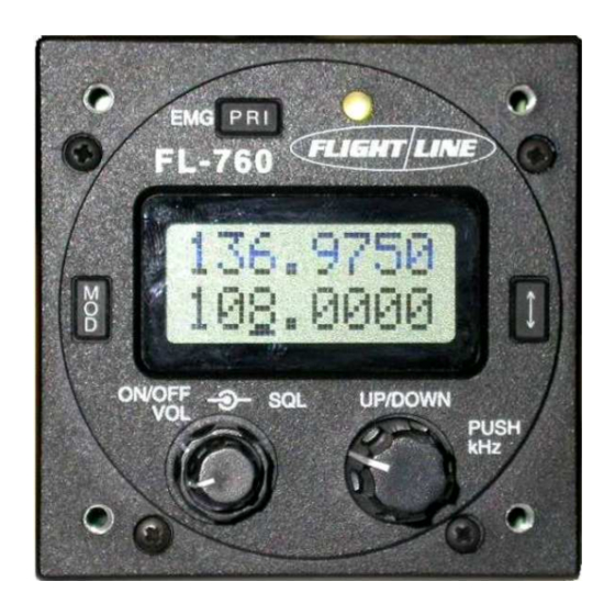
FL- - - - 760
FL
FL
FL
VHF Aircraft
VHF
VHF
VHF
Aircraft Transceiver
Aircraft
Aircraft
Installation / Operation
Installation / Operations Manual
Installation / Operation
Installation / Operation
FL
FL
FL- - - - 760 series
FL
760 series
760 series
760 series
Flightline
Flightline
Flightline
Flightline
12830 E. Mirabeau Parkway
12830 E. Mirabeau Parkway
12830 E. Mirabeau Parkway
12830 E. Mirabeau Parkway
Spokane Valley, WA 99216
Spokane Valley, WA 99216
Spokane Valley, WA 99216
Spokane Valley, WA 99216
Toll free tel.
Toll free
Toll free
Toll free
tel.
tel.: 1
tel.
Toll free fax
Toll free fax: 1
Toll free fax
Toll free fax
http://
http://
http://
http://
VHF AM Aircraft Ra a a a dio
VHF AM Aircraft R
VHF AM Aircraft R
VHF AM Aircraft R
FCC ID: VOSFL760 A
FCC ID:
FCC ID:
FCC ID:
Page 0
760
760
760
Transceiver
Transceiver
Transceiver
s Manual
s Manual
s Manual
: 1- - - - 800
: 1
: 1
800- - - - 235
800
800
235- - - - 3300
235
235
3300
3300
3300
: 1
: 1
: 1- - - - 800
800- - - - 828
800
800
828- - - - 0623
828
828
0623
0623
0623
www.edmo.com
www.edmo.com
www.edmo.com
www.edmo.com
dio
dio
dio
VOSFL760 A
VOSFL760 A
VOSFL760 A
Advertisement
Table of Contents

Related Manuals for FLIGHT LINE FL-760 series

Summary of Contents for FLIGHT LINE FL-760 series
- Page 1 FL- - - - 760 VHF Aircraft Aircraft Aircraft Aircraft Transceiver Transceiver Transceiver Transceiver Installation / Operation Installation / Operations Manual s Manual Installation / Operation Installation / Operation s Manual s Manual FL- - - - 760 series 760 series 760 series 760 series Flightline...
- Page 2 AT T E N T I O N AT T E N T I O N AT T E N T I O N AT T E N T I O N READ ME FIRST READ ME FIRST READ ME FIRST READ ME FIRST FCC WARNING FCC WARNING...
-
Page 3: Table Of Contents
TABLE OF CONTENTS TABLE OF CONTENTS TABLE OF CONTENTS TABLE OF CONTENTS SECTION Page ATTENTION ATTENTION - - - - READ ME FIRST READ ME FIRST ……………………… ……………………… ………………………… …………………………..1 1 1 1 ATTENTION ATTENTION READ ME FIRST READ ME FIRST ………………………... -
Page 4: Introduction
1 INTRODUCTION 1 INTRODUCTION 1 INTRODUCTION 1 INTRODUCTION Thank you for purchasing this quality product from Flightline. This transceiver has been designed and manufactured in Japan specifically for Ultralights, Gliders and General Aviation Aircraft and Helicopters with size and power consumption as the main considerations. -
Page 5: Sailplanes
4 GENERAL 4 GENERAL 4 GENERAL 4 GENERAL The following section is a guide for individual types of aircraft installations. 4.1 Sailplanes 4.1 Sailplanes 4.1 Sailplanes 4.1 Sailplanes Due to the inherent space restriction on most glider instrument panels the FL-760’s 57-mm front panel makes it an excellent choice for confined spaces. -
Page 6: Before Beginning
5 BEFORE BEGINNING 5 BEFORE BEGINNING 5 BEFORE BEGINNING 5 BEFORE BEGINNING INST INST INSTA A A A LLATION INST LLATION LLATION LLATION Again check through the supplied parts list. 5.1 Inst 5.1 Inst 5.1 Inst 5.1 Insta a a a llation parts llation parts llation parts identification llation parts... - Page 7 5. 5. 5. 5.6 6 6 6 Electrical installation Electrical installation Electrical installation Electrical installation ・ Single seat sailplanes: Single seat sailplanes: Single seat sailplanes: Single seat sailplanes: Power, speaker, microphone (prefer electret), PTT located on control column, backlight switch or volume (for viewing) ・...
-
Page 8: Antenna Nstallation
For Motor Glider and Ultralights install the following intercom switch wiring. Wire the center conductor to PIN 5 and the shield to ground. The switch is the same as for the backlight switch described previously or when the switch is not used, you can use voice operation (VOX function). -
Page 9: Operation Of Equipment
6 OPERATION OF EQUIPMENT 6 OPERATION OF EQUIPMENT 6 OPERATION OF EQUIPMENT 6 OPERATION OF EQUIPMENT 6 6 6 6 ..1 1 1 1 General General General General Please read this section for the cor Please read this section for the correct description and operation of this equipment. rect description and operation of this equipment. - Page 10 Press and hold this key for two seconds to activate the emergency frequency. If the external memory button is pushed after the priority memory is called, it becomes a priority scan. ⑤ ⑤ ⑤ ⑤ LED Indicator LED Indicator LED Indicator LED Indicator ・...
-
Page 11: Memory Programming
⑦ ⑦ ⑦ ⑦ External memory External memory toggle toggle External memory External memory toggle toggle This button alternately replaces an active frequency and the standby frequency. Active Standby 6 6 6 6 ..3 3 3 3 Memory programming Memory programming Memory programming Memory programming... -
Page 12: Music Input Music Input
・Busy lockout of transmit. (If the radio is receiving a signal then it can not transmit) ① Hold down the “MOD” button and power on. ② Push the “MOD” button and select the BLO. ③ Push the dial switch and select the OFF or ON. ④... -
Page 13: Specifications
7 SPECIFICATIONS 7 SPECIFICATIONS 7 SPECIFICATIONS 7 SPECIFICATIONS G G G G eneral eneral eneral eneral ・ Frequency range : 118.00 to 136.975MHz (Receive:108.00 to 136.975MHz) ・ Channel spacing : 25kHz ・ Mode : AM (6K00A3E) ・ Number of memory channels : 32 ・... - Page 14 8 8 8 8 HELPFUL HELPFUL HELPFUL HELPFUL HINTS HINTS HINTS HINTS ・ Installing an inline power filter consisting of an LC network may reduce stubborn ignition noise. These are readily available and are commonly used to suppress noise getting into stereo systems.
- Page 15 Certified Aircraft: Certified Aircraft: Certified Aircraft: Certified Aircraft: Any approved VHF communications antenna 6.5mm (1/4") 3.2mm (1/8") 1.6mm (1/16") BNC termination BNC termination BNC termination BNC termination Coaxial cable termination Coaxial cable termination Coaxial cable termination Coaxial cable termination Radio hole cutout dimensions (drawing not to scale) Radio hole cutout dimensions (drawing not to scale) Radio hole cutout dimensions (drawing not to scale) Radio hole cutout dimensions (drawing not to scale)
- Page 16 Limited Liability Warranty Limited Liability Warranty Limited Liability Warranty Limited Liability Warranty Flightline warrants this product to be free from defects in materials and workmanship for 1 year from the date of purchase or the minimum period described by applicable consumer law. If the unit is installed by an organization which holds an avionics installation approval from the FAA, and that organization has co-signed and dated the warranty card, the warranty period shall be deemed to commence from the date of installation.
Need help?
Do you have a question about the FL-760 series and is the answer not in the manual?
Questions and answers
unlock code