Vertiv Netsure User Manual
Hide thumbs
Also See for Netsure:
- User manual (22 pages) ,
- User manual (20 pages) ,
- Installation manual (14 pages)

Related Manuals for Vertiv Netsure


Summary of Contents for Vertiv Netsure
- Page 1 NetSure ™ Control Unit (NCU) User Manual, UM1M830BNA (Revision M, May 12, 2017) Specification Number: 1M830BNA, 1M830DNA Model Number: M830B, M830D Software Version 1.1.70 and 4.1.60 Model M830B Model M830D...
- Page 2 NetSure ™ Control Unit (NCU) User Manual, UM1M830BNA This page is intentionally blank. Spec. No: 1M830BNA, 1M830DNA Code: UM1M830BNA Model No: M830B, M830D Revision M, <ay 12, 2017...
-
Page 3: Table Of Contents
NetSure ™ Control Unit (NCU) User Manual, UM1M830BNA Table of Contents Admonishments Used in this Document ......................viii Introduction ................................. 1 Preface ................................... 1 Overview ................................1 Function Descriptions ............................. 2 Rectifier, Solar Converter, and Converter Control ..................... 2 System Components Monitoring and System Alarms Generation ..............2 Operating Data Acquisition and Data Logs ....................... - Page 4 NetSure ™ Control Unit (NCU) User Manual, UM1M830BNA Local Menu Navigation Keys and Local Display ....................14 Local Display Menus ............................14 Navigating the Menus ..........................14 Using the Web Interface ............................15 Overview ............................... 15 Multiple Browsers Supported ......................... 15 Web Interface Screens ...........................
- Page 5 NetSure ™ Control Unit (NCU) User Manual, UM1M830BNA Manually Forcing LVDs ..........................23 Manually Forcing Relays .......................... 23 Assigning Severity Level to Alarms ......................23 Assigning Relays to Alarms ........................23 Placing the System in Float or Equalize Charge Mode ................23 Viewing/Changing the Float Voltage Setting ...................
- Page 6 NetSure ™ Control Unit (NCU) User Manual, UM1M830BNA Power Split Feature ............................... 32 Overview ............................... 32 How Power Split Works ........................... 32 Operating Modes ............................ 32 Requirements and Conditions ......................... 33 Paralleling the Existing and NCU Power Systems ..................33 Programming the NCU Power Split Feature .....................
- Page 7 NetSure ™ Control Unit (NCU) User Manual, UM1M830BNA Description of Local Display Menus Programmable Parameters ................86 Settings Menu ..............................86 Maintenance Sub-Menu ..........................86 Energy Saving Sub-Menu ..........................86 Alarm Settings Sub-Menu ..........................86 Rect Settings Sub-Menu ..........................87 Batt Settings Sub-Menu ..........................
- Page 8 NetSure ™ Control Unit (NCU) User Manual, UM1M830BNA Battery Test Tab Programmable Parameter Descriptions ............... 130 Time Settings Tab Programmable Parameter Descriptions ..............131 History Log Menu ............................132 Alarm History Log Tab ........................... 132 Battery Test Log Tab ..........................134 Event Log Tab ............................
- Page 9 NetSure ™ Control Unit (NCU) User Manual, UM1M830BNA Accessing the TL1 Port ............................191 Port Connection ............................191 TL1 Port Connection Keep-Alive Feature ....................... 191 TL1 User Session ..............................191 Establishing a Session ..........................191 TL1 Autonomous Messages ......................... 191 TL1 Port Configuration ............................
-
Page 10: Admonishments Used In This Document
NetSure ™ Control Unit (NCU) User Manual, UM1M830BNA Admonishments Used in this Document DANGER! Warns of a hazard the reader will be exposed to that will likely result in death or serious injury if not avoided. (ANSI, OSHA) Danger WARNING! Warns of a potential hazard the reader may be exposed to that could result in death or serious injury if not avoided. -
Page 11: Introduction
Preface Diesel Management Feature These instructions describe the complete functionality of the NetSure™ Control Unit (NCU). Some functionality is dependent on Supervisory Module (SM Modules) Monitoring hardware connected to the NCU. Your system may not utilize all ... -
Page 12: Function Descriptions
NetSure ™ Control Unit (NCU) User Manual, UM1M830BNA Function Descriptions The audible alarm can be silenced by pressing any key on the NCU local interface pad. The audible alarm is also RECTIFIER, SOLAR CONVERTER, AND CONVERTER CONTROL silenced if the fault(s) that triggered the alarm clears. -
Page 13: Battery Charge Temperature Compensation
NetSure ™ Control Unit (NCU) User Manual, UM1M830BNA Battery Discharge Test DC over or under voltage alarm activates, a low voltage disconnection occurs, manual mode is entered, or the system Battery Test Logs (maximum ten [10] tests saved) enters the equalize or test modes. -
Page 14: High And Low Battery Temperature Alarms
NetSure ™ Control Unit (NCU) User Manual, UM1M830BNA Figure 2. Temperature Compensated Voltage Control TempComp Coeff setting (mV/°C). Upper voltage level where temperature compensation clamps the voltage. Limited to the TEMP COMP MAX V high 1V Max (24V System) setting. -
Page 15: Battery Lvd (Low Voltage Disconnect)
NetSure ™ Control Unit (NCU) User Manual, UM1M830BNA battery and saves the results in a battery test log. The NCU stores Battery LVD (Low Voltage Disconnect) ten (10) battery discharge tests. To prevent serious damage to the batteries during a commercial... -
Page 16: Energy Management
NetSure ™ Control Unit (NCU) User Manual, UM1M830BNA occurrence. Power supplied to customer equipment is Any one LVD disconnect. not interrupted. Battery is in charge or discharge, as defined below: The battery LVD circuits can be programmed to open ... -
Page 17: Diesel Management Feature
Hybrid Control menus will not normally be Management feature consists of a Diesel Test. The Diesel Test can displayed unless your NCU has been configured by Vertiv for be performed at specific intervals or a User can manually start the this function. -
Page 18: Hybrid Operation
NetSure ™ Control Unit (NCU) User Manual, UM1M830BNA Capacity Discharge based operation is intended for sites utilizing Under Voltage Alarm 2: If voltage decreases below the only DC powered cooling (heat exchangers, etc.). The cycle period Under Voltage Alarm 2 setting, the Diesel Generator is is determined by User selectable depth of discharge (DOD) of the started and an alarm is raised. -
Page 19: Early Termination Of The Discharge Periods
NetSure ™ Control Unit (NCU) User Manual, UM1M830BNA Figure 6. Charge Voltage Early Termination of the Discharge Periods terminated and recharge cycle is initiated. If grid power becomes available during diesel generator operation, the diesel generator is switched OFF and operations continue on grid power. -
Page 20: Fixed Daily
NetSure ™ Control Unit (NCU) User Manual, UM1M830BNA No Generator Voltage Alarm. No AC supply, 60 sec delay. maximum capacity per discharge cycle is exceeded. The threshold value will be set as default to 40% of battery capacity. It will Relay 2: Battery Alarms. -
Page 21: Communications Function
NetSure ™ Control Unit (NCU) User Manual, UM1M830BNA COMMUNICATIONS FUNCTION The relay outputs can also be connected to customer external equipment, so that the relay output can control or interface with the customer external equipment. The NCU is able to communicate with different equipment or, connect to different equipment for communication. -
Page 22: Operation
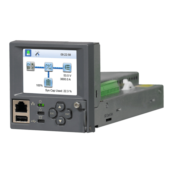
NetSure ™ Control Unit (NCU) User Manual, UM1M830BNA Operation Local Indicators Location and Identification: Refer to Figure Description: There are three (3) indicators located on the NCU’s front panel. Refer to Table 2 for the function of the indicators. Figure 8. -
Page 23: Passwords And Privilege Levels
NetSure ™ Control Unit (NCU) User Manual, UM1M830BNA Passwords and Privilege Levels Users (for local and Web access to the NCU) are set via the Web Interface. NOTE: Anyone can browse the NCU via the local keypad and display. A password is required to change settings. Web access always requires a User name and password to be entered to gain access. -
Page 24: Using The Local Keypad And Display
NetSure ™ Control Unit (NCU) User Manual, UM1M830BNA Using the Local Keypad and Display LOCAL MENU NAVIGATION KEYS AND LOCAL DISPLAY Location and Identification: Refer to Figure Description: There are four (4) menu navigation keys and a local display located on the NCU’s front panel. Refer to... -
Page 25: Using The Web Interface
NetSure ™ Control Unit (NCU) User Manual, UM1M830BNA Using the Web Interface Setting IPv6 Communications Parameters (if controller not set as DHCPv6) NOTE: The NCU supports a 10/100M Ethernet connection. The controller’s IPv6 parameters (IPv6 address, IPv6 prefix, and IPv6 gateway address) must be set to match your company’s OVERVIEW network settings. -
Page 26: Connecting The Controller To Your Local Area Network (Lan) When The System Is Equipped With An Ib4 Board
NetSure ™ Control Unit (NCU) User Manual, UM1M830BNA will get its IP address from a DHCP server on the network. Refer to Procedure “Setting IPv4 Communications Parameters (if controller not set as Before connecting your computer directly to the DHCP)” on page 15 or “Setting IPv6 Communications Parameters controller’s Ethernet port, use the following procedure to... -
Page 27: Connecting A Local Computer Directly To The Controller When The System Is Equipped With An Ib4 Board
NetSure ™ Control Unit (NCU) User Manual, UM1M830BNA step, except that the last part of the IP address needs Some systems may have an IB4 board with a second Ethernet port. to be replaced with any different number. Refer to your system’s documentation for location of the IB4 board (if furnished). -
Page 28: Internet Security Settings For Loading Files Or Downloading Files Into The Ncu
NetSure ™ Control Unit (NCU) User Manual, UM1M830BNA Select Internet Options from the Tools menu. The “Internet Options” window opens. In the “Internet Options” window, select the General tab. Click on the LAN Settings... button. The following window opens. In the LAN Settings window, uncheck the Proxy Server box and click OK. -
Page 29: Logging Into The Controller
NetSure ™ Control Unit (NCU) User Manual, UM1M830BNA In the “Internet Options” window, select the Security tab. Click Add. The NCU URL is listed in the Websites: box. Click Close. Click on Trusted sites. With “Trusted sites” selected, click “Sites”. The following window opens. Uncheck the “Require server verification (https:) for all sites in the... -
Page 30: Common Tasks Performed Via The Local Keypad And/Or Web Interface
NetSure ™ Control Unit (NCU) User Manual, UM1M830BNA Common Tasks Performed via the Local Keypad NOTE: By default, the “User Name” is "admin" and the “Password” is “640275”. The password can be changed if and/or Web Interface necessary (see “Users Tab” on page 145). -
Page 31: Viewing The Ncu Controller's Device Inventory
NetSure ™ Control Unit (NCU) User Manual, UM1M830BNA Viewing the NCU Controller’s Device Inventory Blocking Alarms Local Menu Navigation: Local Menu Navigation: Main Menu / ESC to view Info Screens / ENT to view Inventory. Main Menu / Settings Icon / Alarm Settings / Alarm Blocked. -
Page 32: Adding, Deleting, And Modifying Users
NetSure ™ Control Unit (NCU) User Manual, UM1M830BNA Adding, Deleting, and Modifying Users Setting TL1 Parameters Local Menu Navigation: Refer to the following procedures. None. Setting TL1 Protocol Parameters Web Menu Navigation: Local Menu Navigation: Advance Settings Menu / Users Tab. -
Page 33: Programming The Audible Alarm Feature
NetSure ™ Control Unit (NCU) User Manual, UM1M830BNA Programming the Audible Alarm Feature Manual). then Advance Settings Menu / DO (relay) / Relay (select the other state) Local Menu Navigation: Main Menu / Settings Icon / Alarm Settings / Audible Alarm. -
Page 34: Setting Battery Parameters
NetSure ™ Control Unit (NCU) User Manual, UM1M830BNA Setting Battery Parameters Setting Rectifier Current Limit NOTE: Some parameters are not available for NCU Local Menu Navigation: configurations that enable NCU capability to receive status Main Menu / Settings Icon / Rect Settings / Current Limit (set to information sent from FIAMM SoNick (Sodium Nickel) enabled) then set Curr Limit Pt. -
Page 35: Enabling Solar Mode
NetSure ™ Control Unit (NCU) User Manual, UM1M830BNA Enabling Solar Mode Setting Under Voltage Alarm 2 When solar converters are all installed prior to applying power and Local Menu Navigation: starting system, the NCU will NOT communicate with solar Main Menu / Settings Icon / Other Settings / Under Voltage 2. -
Page 36: Setting Battery Charge Temperature Compensation
NetSure ™ Control Unit (NCU) User Manual, UM1M830BNA Local Menu Navigation: Web Menu Navigation: None. Settings Menu / Battery Tab. Web Menu Navigation: Enter values for the following parameters: Settings Menu / System Tab / Ambient Temp Sensor. Temp Compensation Center, Temp Comp Coefficient (slope),... -
Page 37: Configuring The Ncu Identification Of Solar Converters
NetSure ™ Control Unit (NCU) User Manual, UM1M830BNA Configuring the NCU Identification of Solar Converters Setting Battery Block and Battery Midpoint Monitoring (if equipped with an EIB Assembly) When solar converters are all installed prior to applying power and starting the system, the order in which the NCU identifies the solar... -
Page 38: Setting External Shunts (Connected To The Sm-Du+ Assembly)
NetSure ™ Control Unit (NCU) User Manual, UM1M830BNA Setting External Shunts (connected to the SM-DU+ Assembly) High 1 Curr Alarm Severity High 1 Curr Alarm Relay Local Menu Navigation: None. High 2 Curr Limit Alarm (% of Breaker Value) ... -
Page 39: Clearing The Maintenance Alarm
NetSure ™ Control Unit (NCU) User Manual, UM1M830BNA NOTE: The relay test can be exited at any time by setting the Performing a Manual Battery Discharge Test Relay Test to Disabled. Procedure Manual Test Check that the Rated Battery Capacity is set up correctly When placed in Relay Manual Test Mode, all relays on an IB2 board, for each battery. -
Page 40: Reloading A Backed-Up Ncu Configuration
NetSure ™ Control Unit (NCU) User Manual, UM1M830BNA to your computer so you can restore any custom settings Reloading the Configuration Package you may have made. Local Menu Navigation: NOTE: It is strongly recommended that you save a copy of the None. -
Page 41: Restoring Factory Default Configuration
NetSure ™ Control Unit (NCU) User Manual, UM1M830BNA Return to the Main Screen, and then reboot the Procedure controller (press ENT and ESC at the same time). ALERT! When this procedure is performed, the The screen displays "OK to reboot? ESC to cancel! ENT to controller’s existing configuration and parameter... -
Page 42: Power Split Feature
NetSure ™ Control Unit (NCU) User Manual, UM1M830BNA Fuses Depending on the systems’ configurations, their rectifier capacities, their distribution load capacities, and the Power Split Advance Settings Menu / Fuse Tab. configuration; four operating modes can occur. Low Load Operation... -
Page 43: Requirements And Conditions
NetSure ™ Control Unit (NCU) User Manual, UM1M830BNA Requirements and Conditions Performing the following procedures may expose you to hazards. These procedures should be performed by qualified technicians familiar with the hazards The two DC power systems must be connected in parallel as described in “Paralleling the Existing and NCU Power Systems”... -
Page 44: Programming The Ncu Power Split Feature
NetSure ™ Control Unit (NCU) User Manual, UM1M830BNA Preparing the Existing and NCU Power Systems Note 6: For the size and number of bridge cables between the two power systems, take into consideration Install and turn-up the NCU power system as describe in... -
Page 45: Verifying The Operation Of The Power Split Feature
NetSure ™ Control Unit (NCU) User Manual, UM1M830BNA If the distribution current is lower than 50% of the Set the “Test Voltage Level” to the same value as the test total capacity of the NCU power system, the “Delta voltage of the existing power system. -
Page 46: Fiamm Sonick (Sodium Nickel) Batteries Interface
FIAMM BATTERY INSTALLATION AND USER INSTRUCTIONS Interface_So-Nick-48TL200.pdf; SMCMonitor200.exe The following instructions apply only when FIAMM 48TL200 batteries are used in a NetSure 721 Power System equipped with Installation Requirements for NCU Monitoring of FIAMM an NCU FIAMM battery interface configuration. Battery(s) - Page 47 Refer to the following FIAMM documents for relative instructions: controllers. FIAMM Technical Bulletin, ‘48TL200 Modbus Protocol’, Install RS485 Conductors in Parallel Between the NetSure 721 (Revision 5, Issue Date 21/05/2012), Section “Setting a and Each of the FIAMM Batteries new MODBUS address”.
-
Page 48: Tl1 Interface
NetSure ™ Control Unit (NCU) User Manual, UM1M830BNA Save the new BAUD rate in a .xml file as shown below, NCU TL1 Port then load the file into each battery using the UTILITY-- >UPGRADE function of the program: The NCU TL1 port transports TL1 messages between the NCU and a customer network operations center or client. -
Page 49: Request
NetSure ™ Control Unit (NCU) User Manual, UM1M830BNA Request Error responses are also returned in CSV format. Response Title The request consists of the scheme (http), authority (the IP address of the controller), the path (/data), and the query. The end The header line contains the title for each field, enclosed in double of the query can be specified by # or by the end of the URL. -
Page 50: Example
NetSure ™ Control Unit (NCU) User Manual, UM1M830BNA is provided or the status is not OK and no data is provided. If the The data is request from 12:14 to 12:17. The data in the response status is not OK, the response will be like: would be: 7/1/2014 19:07,1404241623,”No data in this time... -
Page 51: Resolving Alarms
NetSure ™ Control Unit (NCU) User Manual, UM1M830BNA Resolving Alarms Table 5 lists the alarms that are shown in the Web Interface Advance Settings Menu under the Alarms Tab. These are also the possible alarms that display in the alarm screens on the local display and Web Interface. - Page 52 NetSure ™ Control Unit (NCU) User Manual, UM1M830BNA Table 5 Alarm Name Alarm Description Action to Correct System Temp 1 Sensor Fail Temperature sensor #1 failure. System Temp 2 Sensor Fail Temperature sensor #2 failure. Replace temperature sensor. System Temp 3 Sensor Fail Temperature sensor #3 failure.
- Page 53 NetSure ™ Control Unit (NCU) User Manual, UM1M830BNA Table 5 Alarm Name Alarm Description Action to Correct Check why system voltage is low. If there is a Output voltage is lower than the Under mains failure, check if some load could be Under Voltage 1 (24V) Voltage 1 Alarm threshold.
- Page 54 NetSure ™ Control Unit (NCU) User Manual, UM1M830BNA Table 5 Alarm Name Alarm Description Action to Correct Temperature sensor #1 sensing System Temp1 High 2 temperature higher than high temperature threshold 2. Temperature sensor #1 sensing System Temp1 High 1 temperature higher than high temperature threshold 1.
- Page 55 NetSure ™ Control Unit (NCU) User Manual, UM1M830BNA Table 5 Alarm Name Alarm Description Action to Correct Temperature sensor #2 (connected to IB2-1 board and set as Ambient) sensing IB2-1 Temp2 High 2 temperature higher than high temperature threshold 2.
- Page 56 NetSure ™ Control Unit (NCU) User Manual, UM1M830BNA Table 5 Alarm Name Alarm Description Action to Correct Temperature sensor #8 (connected to SM- Temp 1 and set as Ambient) sensing SMTemp1 Temp8 High 2 temperature higher than high temperature threshold 2.
- Page 57 NetSure ™ Control Unit (NCU) User Manual, UM1M830BNA Table 5 Alarm Name Alarm Description Action to Correct NCU DO1 Test Testing NCU Relay DO1. NCU DO2 Test Testing NCU Relay DO2. NCU DO3 Test Testing NCU Relay DO3. NCU DO4 Test Testing NCU Relay DO4.
- Page 58 NetSure ™ Control Unit (NCU) User Manual, UM1M830BNA Table 5 Alarm Name Alarm Description Action to Correct Rectifier Group 2 [3, 4] Alarms Check the connectors and cables or the CAN All Rectifiers Comm Fail No response from all rectifiers.
- Page 59 NetSure ™ Control Unit (NCU) User Manual, UM1M830BNA Table 5 Alarm Name Alarm Description Action to Correct Fan Fail A solar converter’s fan has failed. Replace fan. Solar converter overload. The load is higher than solar converter capacity. If one or more Current Limit A solar converter is in current limit.
- Page 60 NetSure ™ Control Unit (NCU) User Manual, UM1M830BNA Table 5 Alarm Name Alarm Description Action to Correct The equalize charging current exceeds the Abnormal Battery Current Check the alarm setting. alarm setting. Battery charge temperature compensation Temperature Compensation Active is active.
- Page 61 NetSure ™ Control Unit (NCU) User Manual, UM1M830BNA Table 5 Alarm Name Alarm Description Action to Correct Temperature sensor #3 sensing System Temp3 High 2 temperature higher than high temperature threshold 2. Temperature sensor #3 sensing System Temp3 High 1 Check why temperature is high or low.
- Page 62 NetSure ™ Control Unit (NCU) User Manual, UM1M830BNA Table 5 Alarm Name Alarm Description Action to Correct Temperature sensor #2 (connected to EIB-1 board and set as Battery) sensing EIB-1 Temp2 High 2 temperature higher than high temperature threshold 2.
- Page 63 NetSure ™ Control Unit (NCU) User Manual, UM1M830BNA Table 5 Alarm Name Alarm Description Action to Correct … … … Temperature sensor #8 (connected to SM- Temp 8 and set as Battery) sensing SMTemp8 Temp8 High 2 temperature higher than high temperature threshold 2.
- Page 64 NetSure ™ Control Unit (NCU) User Manual, UM1M830BNA Table 5 Alarm Name Alarm Description Action to Correct SMDU Battery Fuse Unit Alarms (SM-DU Module must be present in system) Batt Fuse 1 Alarm Battery fuse #1 is open. Find out and eliminate the reason the fuse is open before replacing.
- Page 65 NetSure ™ Control Unit (NCU) User Manual, UM1M830BNA Table 5 Alarm Name Alarm Description Action to Correct Low Ambient Temperature Alarm Battery string ambient low alarm. High Total Voltage Battery string high voltage alarm. Low Total Voltage Battery string low voltage alarm.
- Page 66 NetSure ™ Control Unit (NCU) User Manual, UM1M830BNA Table 5 Alarm Name Alarm Description Action to Correct DC Fuse Unit Alarms Fuse 1 Alarm DC output fuse #1 is open. Find out and eliminate the reason the fuse is open before replacing. Check for overload …...
- Page 67 NetSure ™ Control Unit (NCU) User Manual, UM1M830BNA Table 5 Alarm Name Alarm Description Action to Correct LVD Unit Alarms (Low voltage disconnect must be present in system) LVD 1 Disconnect LVD1 contactor is in disconnect mode. LVD 2 Disconnect LVD2 contactor is in disconnect mode.
- Page 68 NetSure ™ Control Unit (NCU) User Manual, UM1M830BNA Table 5 Alarm Name Alarm Description Action to Correct Voltage between Line C and Line A is higher Line CA Over Voltage 1 than the High Line Voltage CA Alarm threshold. Check why voltage is high.
- Page 69 NetSure ™ Control Unit (NCU) User Manual, UM1M830BNA Table 5 Alarm Name Alarm Description Action to Correct Phase B voltage is above over voltage 1 Phase B Over Voltage 1 threshold. Check why voltage is high. Phase B voltage is above over voltage 2 Phase B Over Voltage 2 threshold.
- Page 70 NetSure ™ Control Unit (NCU) User Manual, UM1M830BNA Table 5 Alarm Name Alarm Description Action to Correct Voltage between Line C and Line A below Low Line Voltage CA low voltage threshold. Check why voltage is low. Voltage between Line C and Line A below Very Low Line Voltage CA very low voltage threshold.
- Page 71 NetSure ™ Control Unit (NCU) User Manual, UM1M830BNA Table 5 Alarm Name Alarm Description Action to Correct Mains 2 Failure AC input 2 power failure. Mains 3 Failure AC input 3 power failure. No AC input voltage between Line A and Line Mains 1 Uab/Ua Failure B of input 1.
- Page 72 NetSure ™ Control Unit (NCU) User Manual, UM1M830BNA Table 5 Alarm Name Alarm Description Action to Correct AC input 1 voltage between Line C and Line A Mains 1Uca/Uc Under Voltage below under voltage threshold. AC input 2 voltage between Line A and Line B Mains 2Uab/Ua Under Voltage below under voltage threshold.
- Page 73 NetSure ™ Control Unit (NCU) User Manual, UM1M830BNA Table 5 Alarm Name Alarm Description Action to Correct Current1 High 1 Current Current 1 above High 1 limit. Current1 High 2 Current Current 1 above High 2 limit. Current2 High 1 Current Current 2 above High 1 limit.
- Page 74 NetSure ™ Control Unit (NCU) User Manual, UM1M830BNA Table 5 Alarm Name Alarm Description Action to Correct Current1 High 1 Current Current 1 above High 1 limit. Current1 High 2 Current Current 1 above High 2 limit. … … Check why current is high.
- Page 75 NetSure ™ Control Unit (NCU) User Manual, UM1M830BNA Table 5 Alarm Name Alarm Description Action to Correct SMDUP 1 [2, 3, 4, 5, 6, 7, 8] Unit Alarms (SM-DU+ Module must be present in system) Communication Fail Communications failure. Check communications cables.
- Page 76 NetSure ™ Control Unit (NCU) User Manual, UM1M830BNA Table 5 Alarm Name Alarm Description Action to Correct High Water Temperature Generator has high water temperature. Low Oil Pressure Generator has low oil pressure. Periodical maintenance is required to be Periodical Maintenance Required performed.
- Page 77 NetSure ™ Control Unit (NCU) User Manual, UM1M830BNA Table 5 Alarm Name Alarm Description Action to Correct Voltage between Line A and Line B is lower Line AB Under Voltage 1 than the Line AB Under Voltage 1 Alarm threshold.
- Page 78 NetSure ™ Control Unit (NCU) User Manual, UM1M830BNA Table 5 Alarm Name Alarm Description Action to Correct Phase C voltage is above over voltage 1 Phase C Over Voltage 1 threshold. Check why voltage is high. Phase C voltage is above over voltage 2 Phase C Over Voltage 2 threshold.
- Page 79 NetSure ™ Control Unit (NCU) User Manual, UM1M830BNA Table 5 Alarm Name Alarm Description Action to Correct SoNick Battery Alarms Battery Communication Fail Low Ambient Temperature High Ambient Temperature Warning High Ambient Temperature Low Battery Internal Temp High Batt Internal Temp Warning...
-
Page 80: Local Display Menus
NetSure ™ Control Unit (NCU) User Manual, UM1M830BNA Local Display Menus NOTE: These instructions describe the complete functionality Overview of the NCU Controller. Some functionality is dependent on This section provides descriptions of the Local Display Menus. hardware connected to the NCU Controller. Some menu items Refer also to “Passwords and Privilege Levels”... - Page 81 NetSure ™ Control Unit (NCU) User Manual, UM1M830BNA Figure 10. Adjustment Range Restrictions Spec. No: 1M830BNA, 1M830DNA Code: UM1M830BNA [71] Model No: M830B, M830D Revision M, May 12, 2017...
-
Page 82: Main Menu
NetSure ™ Control Unit (NCU) User Manual, UM1M830BNA Main Menu The Main Menu is shown in Figure 11. This is the first screen displayed when the local display is activated by pressing any key on the NCU’s front panel. The current displayed on the Main Menu is “total system load current”. The “total system load current” equals total rectifier current or total solar converter current minus total battery current when battery shunt exists or calculated battery current. -
Page 83: Controller Information Menu (Accessed From The Main Menu)
NetSure ™ Control Unit (NCU) User Manual, UM1M830BNA Controller Information Menu (accessed from the Main Menu) Controller information screens can be accessed from the Main Menu as shown in Figure Figure 12. Controller Information Menu Spec. No: 1M830BNA, 1M830DNA Code: UM1M830BNA... -
Page 84: Alarm Menu
NetSure ™ Control Unit (NCU) User Manual, UM1M830BNA Alarm Menu The Alarm Menu can be accessed from the Main Menu as shown in Figure Figure 13. Alarm Menu Spec. No: 1M830BNA, 1M830DNA Code: UM1M830BNA [74] Model No: M830B, M830D Revision M, May 12, 2017... -
Page 85: Settings Menu
NetSure ™ Control Unit (NCU) User Manual, UM1M830BNA Settings Menu The Settings Menu can be accessed from the Main Menu as shown in Figure Figure 14. Settings Menu Spec. No: 1M830BNA, 1M830DNA Code: UM1M830BNA [75] Model No: M830B, M830D Revision M, May 12, 2017... - Page 86 NetSure ™ Control Unit (NCU) User Manual, UM1M830BNA Figure 14. Settings Menu Spec. No: 1M830BNA, 1M830DNA Code: UM1M830BNA [76] Model No: M830B, M830D Revision M, May 12, 2017...
- Page 87 NetSure ™ Control Unit (NCU) User Manual, UM1M830BNA Figure 14. Settings Menu Spec. No: 1M830BNA, 1M830DNA Code: UM1M830BNA [77] Model No: M830B, M830D Revision M, May 12, 2017...
- Page 88 NetSure ™ Control Unit (NCU) User Manual, UM1M830BNA Figure 14. Settings Menu Spec. No: 1M830BNA, 1M830DNA Code: UM1M830BNA [78] Model No: M830B, M830D Revision M, May 12, 2017...
- Page 89 NetSure ™ Control Unit (NCU) User Manual, UM1M830BNA Figure 14. Settings Menu Spec. No: 1M830BNA, 1M830DNA Code: UM1M830BNA [79] Model No: M830B, M830D Revision M, May 12, 2017...
-
Page 90: Start Wizard Sub-Menu (Accessed From Settings Menu)
NetSure ™ Control Unit (NCU) User Manual, UM1M830BNA Start Wizard Sub-Menu (accessed from Settings Menu) The Start Wizard menu can be accessed from the Settings Menu (in “Other Settings” sub-menu). See Figure 15 for Start Wizard menu. Figure 15. Start Wizard Sub-Menu (accessed from Setting's Menu) Spec. -
Page 91: Input Power Menu
NetSure ™ Control Unit (NCU) User Manual, UM1M830BNA Input Power Menu The Input Power Menu can be accessed from the Main Menu as shown in Figure Figure 16. Input Power Menu Spec. No: 1M830BNA, 1M830DNA Code: UM1M830BNA [81] Model No: M830B, M830D... -
Page 92: Module Menu
NetSure ™ Control Unit (NCU) User Manual, UM1M830BNA Module Menu The Module Menu can be accessed from the Main Menu as shown in Figure Figure 17. Module Menu Spec. No: 1M830BNA, 1M830DNA Code: UM1M830BNA [82] Model No: M830B, M830D Revision M, May 12, 2017... -
Page 93: Dc Menu
NetSure ™ Control Unit (NCU) User Manual, UM1M830BNA DC Menu The DC Menu can be accessed from the Main Menu as shown in Figure Figure 18. DC Menu Spec. No: 1M830BNA, 1M830DNA Code: UM1M830BNA [83] Model No: M830B, M830D Revision M, May 12, 2017... -
Page 94: Battery Menu
NetSure ™ Control Unit (NCU) User Manual, UM1M830BNA Battery Menu The Battery Menu can be accessed from the Main Menu as shown in Figure 19 Figure 20. The actual display of the Battery Menu is dependent on the NCU configuration. - Page 95 NetSure ™ Control Unit (NCU) User Manual, UM1M830BNA Figure 20. Battery Menu Spec. No: 1M830BNA, 1M830DNA Code: UM1M830BNA [85] Model No: M830B, M830D Revision M, May 12, 2017...
-
Page 96: Description Of Local Display Menus Programmable Parameters
NetSure ™ Control Unit (NCU) User Manual, UM1M830BNA Description of Local Display Menus ENERGY SAVING SUB-MENU Programmable Parameters ECO Mode: Enables or disables the Energy Optimization Mode feature for all rectifiers. When enabled, the The following are descriptions of the programmable parameters following parameters can be set. -
Page 97: Rect Settings Sub-Menu
NetSure ™ Control Unit (NCU) User Manual, UM1M830BNA ClrAllConvCommF: Clears an “All Converter Comm Fail” EQ Voltage(S): Equalize charge output voltage setting alarm. for solar when the “Solar Mode” setting under “System” TAB in Web Interface is set to either “RECT-SOLAR” or ... -
Page 98: Battery Test Sub-Menu
NetSure ™ Control Unit (NCU) User Manual, UM1M830BNA NOTE: If the power system has been automatically placed in System T1, System T2, System T3, IB2-1 T1, IB2-1 T2, EIB- Equalize mode, disabling Auto EQ will not return the system to 1 T1, EIB-1 T2, SMTemp1 T1, …, SMTemp1 T8, SMTemp8... -
Page 99: Ac Settings Sub-Menu
NetSure ™ Control Unit (NCU) User Manual, UM1M830BNA HTD Recon Point: Sets temperature at which a reconnect Phase A Voltage High 2 (Nominal Plus "V Mains Fail will occur following a High Temperature Disconnect. Alarm 2 Percent of Nominal) Phase A used in the example above, Phase B and Phase C ... -
Page 100: Other Settings Sub-Menu
NetSure ™ Control Unit (NCU) User Manual, UM1M830BNA Default Gateway: Sets the controller's IPv4 gateway NOTE: When primary or secondary is selected, the NCU will address. Enter the address in the format start auto configure. This process will take more than three (3) nnn.nnn.nnn.nnn,... - Page 101 NetSure ™ Control Unit (NCU) User Manual, UM1M830BNA Start Wizard Now (see Figure 15). OK to Exit? Site Name Sub-Menu Press ESC to end the wizard or press ENT to continue the wizard to enter the following parameters. Enter the site name and other site information.
- Page 102 NetSure ™ Control Unit (NCU) User Manual, UM1M830BNA IP Address: Sets the controller's IP address. Enter the address in the format nnn.nnn.nnn.nnn, where 0 ≤ nnn ≤ 255. The address must be a valid address and must not be 255.255.255.255.
-
Page 103: Web Interface Screens
NetSure ™ Control Unit (NCU) User Manual, UM1M830BNA Web Interface Screens Overview of Web Function This section provides descriptions of the Web Interface Screens. Refer also to “Passwords and Privilege Levels” on page 13 and “Using the Web Interface” on page 15. For Local Display Menus, refer to “Local Display Menus” on page 70. - Page 104 NetSure ™ Control Unit (NCU) User Manual, UM1M830BNA Figure 22. NCU Homepage with Solar Converters The homepage window is divided into six areas: System Status Information Area System Specifications Information Area Controller Specifications Information Area Alarms Area System Status Area Menu Navigation Area Spec.
-
Page 105: System Status Information Area
NetSure ™ Control Unit (NCU) User Manual, UM1M830BNA System Status Information Area Output voltage and output current are displayed here. System Specifications Information Area System specifications are displayed here. Controller Specifications Information Area Controller specifications are displayed here. Figure 23. -
Page 106: Alarms Area
NetSure ™ Control Unit (NCU) User Manual, UM1M830BNA Alarms Area Any alarms active in the power system are shown in this area. When viewing the alarms, click the “arrow” icon to collapse the alarm list. Click the "arrow" icon to expand the alarm list. Also located next to the “arrow”... -
Page 107: System Status Area
NetSure ™ Control Unit (NCU) User Manual, UM1M830BNA System Status Area System status is displayed in this area and consists of a Power System tab and a General Status tab. Temperature Readings The temperature sensor set as “Ambient Temp Sensor” (Settings Menu / System Tab) is the sensor which displays the ambient temperature on the Power System tab. -
Page 108: Device Group Status Pages
NetSure ™ Control Unit (NCU) User Manual, UM1M830BNA Device Group Status Pages The power system status block diagram has interactive links. Clicking on a link takes you to that device group’s status page. A device group’s status page displays current or logged operating parameters for that device group. - Page 109 NetSure ™ Control Unit (NCU) User Manual, UM1M830BNA Module (Rectifier, Converter, Solar Converter) Device Group Status Page Clicking on a rectifier, converter, or solar converter icon on the power system status block diagram opens up the status page for the module’s Device Group.
- Page 110 NetSure ™ Control Unit (NCU) User Manual, UM1M830BNA Individual Rectifier Status Page Displayed on the Rectifier Device Group status page are the individual rectifiers installed in the system. Click on an individual rectifier icon to display its status such as "Current", etc.
- Page 111 NetSure ™ Control Unit (NCU) User Manual, UM1M830BNA Individual Rectifier Settings Page Figure 29, if you hover the mouse pointer on an individual rectifier icon , this icon changes to . Click to go to the individual rectifier settings page. Click to go back to the individual rectifier status page.
- Page 112 NetSure ™ Control Unit (NCU) User Manual, UM1M830BNA NOTE: Settings that appear "grayed out" can only be made when the controller is in the "manual control" state. If the controller is set for "automatic" control, change the “Auto/Manual State” setting first to the “Manual” setting.
- Page 113 NetSure ™ Control Unit (NCU) User Manual, UM1M830BNA Solar Converter Device Group Status Page Tab This tab displays status values such as “Total Current”, “Number of Solar Converters”, etc. Figure 33. Solar Converter Device Group Status Page Tab Individual Solar Converter Status Page Displayed on the Solar Converter Device Group status page are the individual solar converters installed in the system.
- Page 114 NetSure ™ Control Unit (NCU) User Manual, UM1M830BNA Individual Solar Converter Settings Page Figure 35, hover the mouse pointer on an individual solar converter icon , this icon changes to . Click to go to the individual solar converter settings page. Click to go back to the individual solar converter status page.
- Page 115 NetSure ™ Control Unit (NCU) User Manual, UM1M830BNA Converter Device Group Status Page Tab This tab displays status values such as “Total Current”, “Number of Converters”, etc. Figure 37. Converter Device Group Status Page Tab Individual Converter Status Page Displayed on the Converter Device Group status page are the individual converters installed in the system. Click on an individual converter icon to display its status such as "Current", etc.
- Page 116 NetSure ™ Control Unit (NCU) User Manual, UM1M830BNA Individual Converter Settings Page Figure 37, hover the mouse pointer on an individual converter icon , this icon changes to . Click to go to the individual converter settings page. Click to go back to the individual converter status page.
- Page 117 NetSure ™ Control Unit (NCU) User Manual, UM1M830BNA DC Device Group Status Page Clicking on the DC icon on the power system status block diagram opens up the status page for the DC Device Group. The DC Device Group status page contains multiple tabs (depending on the DC equipment installed in your power system). This includes DC, SMDU, SMDUP, and EIB.
- Page 118 NetSure ™ Control Unit (NCU) User Manual, UM1M830BNA Battery Device Group Status Page Clicking on the battery icon on the power system status block diagram opens up the status page for the Battery Device Group. The Battery Device Group status page displays battery status values such as "Battery Management State" and "Battery Temp". The actual...
- Page 119 NetSure ™ Control Unit (NCU) User Manual, UM1M830BNA Figure 44. Battery Device Group Status Page Figure 45. Battery Device Group Status Page (FIAMM SoNick [Sodium Nickel] Battery) Spec. No: 1M830BNA, 1M830DNA Code: UM1M830BNA [109] Model No: M830B, M830D Revision M, May 12, 2017...
- Page 120 NetSure ™ Control Unit (NCU) User Manual, UM1M830BNA Individual Battery Status Page Displayed on the Battery Device Group status page are the individual batteries installed in the system. Hover the mouse over an individual battery icon to display its status such as "Battery Rating". The actual display of an Individual Battery status is dependent on the...
- Page 121 NetSure ™ Control Unit (NCU) User Manual, UM1M830BNA Figure 48. Individual Battery Status Page (FIAMM SoNick [Sodium Nickel] Battery) Spec. No: 1M830BNA, 1M830DNA Code: UM1M830BNA [111] Model No: M830B, M830D Revision M, May 12, 2017...
- Page 122 NetSure ™ Control Unit (NCU) User Manual, UM1M830BNA Individual Battery Capacity Trend Diagram or Info Screen Displayed on the Battery Device Group status page are the individual batteries installed in the system. Click on an individual battery (Battery 1 or Battery 2) to display its "Capacity Trend Diagram" or “info screen”. The actual display of an individual battery capacity trend...
- Page 123 NetSure ™ Control Unit (NCU) User Manual, UM1M830BNA Individual Battery Settings Page Figure Figure 43, or Figure 44; click on the symbol located on an individual battery icon to go to the individual battery settings page. Click to go back to the individual battery status page. See...
- Page 124 NetSure ™ Control Unit (NCU) User Manual, UM1M830BNA Figure 52. Individual Battery Settings Page (SMDU#Battery #) Rated Capacity: Enter the battery string's rated capacity. Figure 53. Individual Battery Settings Page (EIB-#Battery #) Battery Management: Select Yes to use the battery management feature and No to not use the feature for this battery.
-
Page 125: General Status Tab
NetSure ™ Control Unit (NCU) User Manual, UM1M830BNA GENERAL STATUS TAB The General Status tab displays general status information as shown in the following illustration. NOTE: Temperature items are displayed only if temperature probes are connected. Figure 55. General Status Tab Spec. -
Page 126: Menu Navigation Area
NetSure ™ Control Unit (NCU) User Manual, UM1M830BNA Menu Navigation Area Available menus are displayed in this area. When a menu is clicked on, the system status screen is replaced with the selected menu’s screen. Note that there is a menu item named HOME to return to the system status screen. - Page 127 NetSure ™ Control Unit (NCU) User Manual, UM1M830BNA Figure 57. Settings Menu Spec. No: 1M830BNA, 1M830DNA Code: UM1M830BNA [117] Model No: M830B, M830D Revision M, May 12, 2017...
-
Page 128: Changing Programmable Parameters In The Settings Menu
NetSure ™ Control Unit (NCU) User Manual, UM1M830BNA Changing Programmable Parameters in the Settings Menu To change a programmable parameter, select or enter a new value for the parameter then click on “Set” to change the value. NOTE: Settings that appear "grayed out" can only be made when the controller is in the "manual control" state. If the controller is set for "automatic"... -
Page 129: System Tab Programmable Parameter Descriptions
NetSure ™ Control Unit (NCU) User Manual, UM1M830BNA (bat), SMTemp8 Temp1 (bat), …, SMTemp8 Temp8 (bat)] set as battery temperature probes. When used with an SM-BRC, you can select to average the SM-BRC temperature probe readings (Average SMBRC setting). Temp Comp Coefficient: Sets the temperature compensation slope or rate of change per °C above or below the "Temperature Compensation Center"... - Page 130 NetSure ™ Control Unit (NCU) User Manual, UM1M830BNA EIB-1 Temp1 (bat), EIB-1 Temp2 (bat), SMTemp1 Temp1 (bat), …, SMTemp1 Temp8 (bat), SMTemp8 Temp1 (bat), …, SMTemp8 Temp8 (bat)]. You can also select Maximum or Average which takes the maximum or average reading of the temperature probes [any of System Temp1 (bat), System Temp2 (bat), System Temp3 (bat), IB2-1 Temp1 (bat), IB2-1 Temp2 (bat), EIB-1 Temp1 (bat), EIB-1 Temp2 (bat), SMTemp1 Temp1 (bat), …, SMTemp1 Temp8 (bat), SMTemp8 Temp1 (bat), …,...
- Page 131 NetSure ™ Control Unit (NCU) User Manual, UM1M830BNA Delta Voltage: The offset voltage that the power system designated as “System A” in a "Power Split" configuration is set to. It is suggested to leave this value at the default (0.5 volts).
-
Page 132: Battery Tab Programmable Parameter Descriptions
NetSure ™ Control Unit (NCU) User Manual, UM1M830BNA SOLAR: If you have only solar converters in the system, set Solar Mode to “SOLAR”. Reboot the controller (see “Rebooting the Controller” on page 31) after changing setting to SOLAR. HTD Point: Sets high temperature limit at which LVD1 and/or LVD2 contactors will open (disconnect) if the HTD1 and/or HTD2 features are enabled. - Page 133 NetSure ™ Control Unit (NCU) User Manual, UM1M830BNA Temp Comp Coefficient: Sets the temperature compensation slope or rate of change per °C above or below the "Temperature Compensation Center" setting. This value is expressed in millivolt per °C per string (mV/°C/str). For example, for a rate of change of 72 mV/°C/str in a 24-cell 48V nominal battery string, the rate of change is 3 mV per cell.
- Page 134 NetSure ™ Control Unit (NCU) User Manual, UM1M830BNA Equalize Stop Delay Time: See "Equalize Stop Current" above. NOTE: If the power system has been automatically placed in Equalize mode, disabling Automatic Equalize will not return the system to Float mode until the current Equalize cycle is completed. To return immediately to Float mode, select Float Charge for the Equalize/Float Charge Control setting.
-
Page 135: Eco Tab Programmable Parameter Descriptions
NetSure ™ Control Unit (NCU) User Manual, UM1M830BNA ECO Tab Programmable Parameter Descriptions ECO Mode: Enables or disables the Energy Optimization Mode feature for all rectifiers. When enabled, the following parameters can be set. ALERT! The Energy Optimization Mode should NOT be used in systems that operate without batteries. -
Page 136: Temp Probes Tab Programmable Parameter Descriptions
NetSure ™ Control Unit (NCU) User Manual, UM1M830BNA SMDU 1 LVD LVD 1: Enables or disables LVD 1. LVD 1 Mode: Sets LVD 1 to disconnect on a voltage or time setpoint. LVD 1 Disconnect Voltage: LVD 1 low voltage disconnect setting (when LVD set for voltage) ... -
Page 137: Rectifiers Tab Programmable Parameter Descriptions
NetSure ™ Control Unit (NCU) User Manual, UM1M830BNA EIB-1 Temp2 High 2: Sets temperature port 2 on the EIB-1 board “Temperature High 2” alarm point. EIB-1 Temp2 High 1: Sets temperature port 2 on the EIB-1 board “Temperature High 1” alarm point. -
Page 138: Dc/Dc Converters Tab Programmable Parameter Descriptions
NetSure ™ Control Unit (NCU) User Manual, UM1M830BNA Turn On when AC Over: Enables or disables the "Rectifier On at AC Overvoltage" feature. When the system is operating on “weak” grid input power (i.e. diesel generator), the input voltage may have a very high peak voltage which may cause a rectifier not to turn on. -
Page 139: Solar Tab Programmable Parameter Descriptions
NetSure ™ Control Unit (NCU) User Manual, UM1M830BNA Over Voltage: Sets the converter Over Voltage alarm point. Over Current: Sets the converter Over Current alarm point. Converter Trim(24V): Temporarily sets the output voltage for all converters when the controller is in Manual mode. Setting returns to original when controller is returned to the Auto mode. -
Page 140: Battery Test Tab Programmable Parameter Descriptions
NetSure ™ Control Unit (NCU) User Manual, UM1M830BNA Confirm Solar Converter ID: After changing solar converter ID assignments, use this menu item to confirm the change. The only selection is Yes. Once Yes is selected and confirmed, the ID setting of all solar converters is updated. -
Page 141: Time Settings Tab Programmable Parameter Descriptions
NetSure ™ Control Unit (NCU) User Manual, UM1M830BNA Clear Battery Test Fail Alarm: Clears a battery test fail alarm. The only selection is Yes. Once Yes is selected and confirmed, the alarm clears. Clear Discharge Curr: Clears a discharge current imbalance alarm. The only selection is Yes. Once Yes is selected and confirmed, the alarm clears. -
Page 142: History Log Menu
NetSure ™ Control Unit (NCU) User Manual, UM1M830BNA HISTORY LOG MENU The History Log Menu allows you to view and save the various logs available in the NCU. Alarm History Log Tab Select Device and Time Select the "Device" to query from the drop-down list box. Select the "from" and "to" time. - Page 143 NetSure ™ Control Unit (NCU) User Manual, UM1M830BNA Upload Alarm History Log Click “Upload” to open the log into another window. You can then save the log as an .html (Web page) or .txt (text) file. Figure 61. Alarm History Log Upload Spec.
-
Page 144: Battery Test Log Tab
NetSure ™ Control Unit (NCU) User Manual, UM1M830BNA Battery Test Log Tab Select Battery Test Number Select the Battery Test Log to query from the drop-down list box. Battery test #1 is the most recent. Figure 62. Battery Test Log Number Selection Query Selected Battery Test Click “Query”... - Page 145 NetSure ™ Control Unit (NCU) User Manual, UM1M830BNA Upload Battery Test Log Click “Upload” to open the log into another window. You can then save the log as an .html (Web page) or .txt (text) file. Figure 64. Battery Test Log Upload Spec.
-
Page 146: Event Log Tab
NetSure ™ Control Unit (NCU) User Manual, UM1M830BNA Event Log Tab Select Time Select the "from" and "to" time. Figure 65. Event Log Time Selection Query Event Log Click “Query” to query the Event Log. The Web page displays the last 500 entries. - Page 147 NetSure ™ Control Unit (NCU) User Manual, UM1M830BNA Upload Event Log Click “Upload” to open the log into another window. You can then save the log as an .html (Web page) or .txt (text) file. Figure 67. Event Log Upload Spec.
-
Page 148: Data History Log Tab
NetSure ™ Control Unit (NCU) User Manual, UM1M830BNA Data History Log Tab Select Device and Time Select the "Device" to query from the drop-down list box. Select the "from" and "to" time. Figure 68. Data History Log Device and Time Query Data History Log Click “Query”... - Page 149 NetSure ™ Control Unit (NCU) User Manual, UM1M830BNA Upload Data History Log Click “Upload” to open the log into another window. You can then save the log as an .html (Web page) or .txt (text) file. Figure 70. Data History Log Upload Spec.
-
Page 150: System Log Tab
NetSure ™ Control Unit (NCU) User Manual, UM1M830BNA System Log Tab Select Time Select the "from" and "to" time. Figure 71. System Log Time Selection Query System Log Click “Query” to query the System Log. The Web page displays the last 500 entries. - Page 151 NetSure ™ Control Unit (NCU) User Manual, UM1M830BNA Upload System Log Click “Upload” to open the log into another window. You can then save the log as an .html (Web page) or .txt (text) file. Figure 73. System Log Upload Spec.
-
Page 152: System Inventory Menu
NetSure ™ Control Unit (NCU) User Manual, UM1M830BNA SYSTEM INVENTORY MENU The System Inventory Menu allows you to view product information of the intelligent devices (i.e. rectifiers, converters, SMDUs, IB, etc.) connected to the controller. Figure 74. System Inventory Menu Spec. - Page 153 NetSure ™ Control Unit (NCU) User Manual, UM1M830BNA Figure 75. System Inventory Menu (with FIAMM SoNick [Sodium Nickel] Battery) Spec. No: 1M830BNA, 1M830DNA Code: UM1M830BNA [143] Model No: M830B, M830D Revision M, May 12, 2017...
-
Page 154: Advanced Settings Menu
NetSure ™ Control Unit (NCU) User Manual, UM1M830BNA ADVANCED SETTINGS MENU The Advanced Settings Menu allows you to change (if you have the proper privilege level programmed in your User settings) the settings of the various advanced programmable parameters. Settings are grouped per function. Select a tab in the Advanced Settings Menu to change that functions programmable parameters. -
Page 155: Users Tab
NetSure ™ Control Unit (NCU) User Manual, UM1M830BNA Users Tab You can add, edit, and delete Users. These are the Users that can log onto the controller both locally (local display access) or remotely using the Web Interface. Figure 77. - Page 156 NetSure ™ Control Unit (NCU) User Manual, UM1M830BNA NOTE: To reset the form (i.e. to start over) and erase all information entered, click on the “Reset” button. Deleting a User Select the User to be deleted from those listed in the "User Information" list.
-
Page 157: Snmp Tab
NetSure ™ Control Unit (NCU) User Manual, UM1M830BNA SNMP Tab Configures SNMP V2 and V3 parameters. Accepted Trap Level Parameter Description Accepted Trap Level: Sets SNMP V2 and V3 trap level. Adding an Entry Enter the parameters in the parameter fields. - Page 158 NetSure ™ Control Unit (NCU) User Manual, UM1M830BNA NMSV2 Configuration Description (Network Management System) Configures SNMP Version 1 and 2 parameters. You can configure the following parameters. NMS IP: The permitted IP to access the NMSV2 agent. Check the IPV6 box when entering an IPV6 address.
- Page 159 NetSure ™ Control Unit (NCU) User Manual, UM1M830BNA NMSV3 Configuration Description (Network Management System) Configures SNMP Version 3 parameters. You can configure the following parameters. Use Name: The permitted User to access the NMSV3 agent. Priv Password DES: The privacy DES password used to encrypt the data.
-
Page 160: Language Tab
NetSure ™ Control Unit (NCU) User Manual, UM1M830BNA Language Tab The local display and Web Interface always has an English language option. Multiple local languages are also supported. One local language option is displayed at a time with the English language option. To select another local language option to display, use the Web Interface Language Tab. -
Page 161: Sw Maintenance Tab
NetSure ™ Control Unit (NCU) User Manual, UM1M830BNA SW Maintenance Tab Allows you to perform software maintenance procedures. Figure 82. SW Maintenance Tab Auto Config Procedure The auto configuration feature scans the system for intelligent equipment connected to controller (such as SMDU, IB and EIB) and configures these into the controller automatically. - Page 162 NetSure ™ Control Unit (NCU) User Manual, UM1M830BNA Restore Factory Default Configuration Procedure See also “Restoring Factory Default Configuration” on page 31. This procedure is typically used to restore any changes made to any settings, relay assignments, alarm severities, or signal names. This file is not shipped with the system.
- Page 163 NetSure ™ Control Unit (NCU) User Manual, UM1M830BNA Retrieve Setting Param.run Procedure See also “Backing Up the NCU Configuration” on page 29. A file named “SettingParam.run” is automatically created/appended by the controller whenever a User (or the factory at the time of shipment) makes changes to any parameter settings via the local display or Web Interface.
- Page 164 NetSure ™ Control Unit (NCU) User Manual, UM1M830BNA Upload/Download Procedure See also “Backing Up the NCU Configuration” on page 29, “Reloading a Backed-Up NCU Configuration” on page 30, and “Upgrading the NCU Using an Application ("All") Package” on page 30.
- Page 165 NOTE: A Language Package is a package of files containing all the default names of the parameters in two languages. Typically these would be in English and Chinese. The language package cannot be changed by the User. Consult Vertiv if a different language package is required.
-
Page 166: Alarms Tab
NetSure ™ Control Unit (NCU) User Manual, UM1M830BNA Alarms Tab NOTE: This list is dynamic and will only show you the equipment that you have in your system. Allows you to define the alarm level for each alarm. (See also Table 1 on page 2.) -
Page 167: Di Alarms Tab
NetSure ™ Control Unit (NCU) User Manual, UM1M830BNA DI Alarms Tab Allows you to change the digital input alarm signal full name (name displayed in the Web Interface menus). Allows you to change the digital input alarm signal abbreviation name (name displayed in the local display menus). - Page 168 NetSure ™ Control Unit (NCU) User Manual, UM1M830BNA Procedure To modify the digital input alarm parameters, click on the “Modify” button for that digital input alarm signal. The following window opens. Figure 92. Setting DI Alarm Change the following parameters as desired and click on “Set”.
-
Page 169: Do (Relay) Tab
NetSure ™ Control Unit (NCU) User Manual, UM1M830BNA DO (relay) Tab Allows you to use the relay test feature. Relay Test: Sets the Relay Test feature to Automatic, Manual, or Disabled. Refer to “Using the Relay Test Feature” on page Relay Test Time: Sets the Relay Test Time for the Automatic Relay Test feature. - Page 170 NetSure ™ Control Unit (NCU) User Manual, UM1M830BNA Procedure To change the relay signal full name (name displayed in the Web Interface menus), click on the “Modify” button for that relay. The following window opens. Figure 94. Changing Relay Signal Full Name Spec.
-
Page 171: Shunts Tab
NetSure ™ Control Unit (NCU) User Manual, UM1M830BNA Shunts Tab Allows you to change the shunts signal full name (name displayed in the Web Interface menus). Allows you to change the shunts signal abbreviation name (name displayed in the local display menus). - Page 172 NetSure ™ Control Unit (NCU) User Manual, UM1M830BNA Procedure To modify the shunt parameters, click on the “Modify/View” button for that shunt. The following window opens. Figure 96. Setting Shunt Parameters Change the following parameters as desired and click on “Set”.
- Page 173 NetSure ™ Control Unit (NCU) User Manual, UM1M830BNA Break Value: Enter the value desired as the reference for the high current alarms (typically the rating of the breakers or fuses fed by the shunt, if applicable). High 1 Curr Limit Alarm: Enter the percentage value of the "Break Value" for alarm.
-
Page 174: Fuse Tab
NetSure ™ Control Unit (NCU) User Manual, UM1M830BNA Fuse Tab Allows you to change the fuse full name (name displayed in the Web Interface menus). Allows you to change the fuse abbreviation name (name displayed in the local display menus). - Page 175 NetSure ™ Control Unit (NCU) User Manual, UM1M830BNA Procedure To change the fuse name, click on the “Modify” button for that fuse. The following window opens. Figure 98. Changing Fuse Names Change the following parameters as desired and click on “Set”.
-
Page 176: Alarm Report Tab
NetSure ™ Control Unit (NCU) User Manual, UM1M830BNA Alarm Report Tab In the SMTP section, you can set the Alarm Report Feature and part of the Forget Password Feature (you must also set an E-Mail address in the User tab for the Forget Password feature). - Page 177 NetSure ™ Control Unit (NCU) User Manual, UM1M830BNA Privilege: Select Enabled (if email authentication is required) or Disabled as required (see your IT department). When enabled, set the following parameters. SMTP Account: SMTP account number. Obtain from your IT department.
-
Page 178: Generator Tab
NetSure ™ Control Unit (NCU) User Manual, UM1M830BNA Generator Tab If you have a special configuration with this feature, you can set the various generator related parameters. Figure 100. Generator Tab Changing Programmable Parameters in the Generator Tab To change a programmable parameter, select or enter a new value for the parameter then click on “Set” to change the value. - Page 179 NetSure ™ Control Unit (NCU) User Manual, UM1M830BNA DG Run Time at High Temp: Sets the diesel generator run time in the high temperature condition. DI for Grid: Sets the digital input monitoring the grid. Diesel Alarm Delay: Sets diesel alarm delay.
-
Page 180: Power Split Tab
NetSure ™ Control Unit (NCU) User Manual, UM1M830BNA Power Split Tab You can configure the advanced power split parameters and associated digital input signals. Refer to “Power Split Feature” on page 6 and “Power Split Feature” on page 32 for more information on the Power Split feature. - Page 181 NetSure ™ Control Unit (NCU) User Manual, UM1M830BNA Procedure Select the power split mode (enabled or disabled). Click on SET. Procedure If low voltage disconnect functions are to be used in a power split configuration, they must be implemented in the existing power system and signals from its control unit must be connected to the NCU.
-
Page 182: Monitor Protocol Tab
NetSure ™ Control Unit (NCU) User Manual, UM1M830BNA Monitor Protocol Tab You can select "EEM", "YDN23", "Modbus" or “TL1” as the protocol. To make the new protocol valid, click the “Valid after Restart" button. Figure 103. Monitor Protocol Tab Figure 104. - Page 183 NetSure ™ Control Unit (NCU) User Manual, UM1M830BNA EEM Protocol You can set EEM protocol parameters. Figure 105. EEM Protocol Protocol Type: Select EEM, RSOC, or SOC/TPE per site requirements. Protocol Media: Select RS-232, Modem, IPV4, or IPV6 per site requirements.
- Page 184 NetSure ™ Control Unit (NCU) User Manual, UM1M830BNA YDN23 Protocol You can set YDN23 protocol parameters. Figure 106. YDN23 Protocol Protocol Media: Select RS-232, Modem, or IPV4 per site requirements. Self Address: Enter the parameter per site requirements.
- Page 185 NetSure ™ Control Unit (NCU) User Manual, UM1M830BNA Modbus Protocol You can set Modbus protocol parameters. Figure 107. Modbus Protocol Protocol Media: Select RS-232, Modem, or IPV4 per site requirements. Self Address: Enter the parameter per site requirements.
- Page 186 NetSure ™ Control Unit (NCU) User Manual, UM1M830BNA TL1 Protocol You can enable the TL1 port and set TL1 protocol parameters. Figure 108. TL1 Protocol Port Activation: Select Enabled to enable the NCU TL1 port. The following parameters appear.
-
Page 187: Clear Data Tab
NetSure ™ Control Unit (NCU) User Manual, UM1M830BNA Clear Data Tab Select the data log to be cleared from those listed in the drop-down list box. Click on the “Clear” button to clear the corresponding data. Figure 109. Clear Data Spec. -
Page 188: Tl1 Aid Group Tab
NetSure ™ Control Unit (NCU) User Manual, UM1M830BNA TL1 AID Group Tab You can program up to thirty-two (32) Access Identifiers (AID) and assign a Sub-Access Identifier (Sub- Aid) to the access identifier. Constraints: The AID Name that can also have a Sub AID Name Prefix has a 16 character maximum limit. - Page 189 NetSure ™ Control Unit (NCU) User Manual, UM1M830BNA sub-entity within an NMA system, such as a specific rectifier. Only alpha-numeric characters can be entered for this parameter. TL1 uses specific values for this parameter. Refer to TA-NWT-001360, Table 4-1. Procedure Select the Access Identifier (AID) to be programmed by selecting the circle next to its number in the list.
-
Page 190: Tl1 Aid Signal Tab
NetSure ™ Control Unit (NCU) User Manual, UM1M830BNA TL1 AID Signal Tab This tab is used to enable/disable and configure the pre-defined TL1 signals. You can enable or disable a signal and set attributes of a signal (i.e. set condition type, condition description, notification code, etc.). - Page 191 NetSure ™ Control Unit (NCU) User Manual, UM1M830BNA Sample Signal: This is the NCU sample signal which is associated to the alarm signal. This signal is used to provide a present value (<monval>) for the TL1 signal (e.g., voltage or temperature reading). This value is used for TL1 commands and reports.
-
Page 192: Accessing The Controller Via A Network Management System (Nms)
NetSure ™ Control Unit (NCU) User Manual, UM1M830BNA Accessing the Controller via a Network NMS SUPPORTED BY SNMP V2 Management System (NMS) The SNMP agent of the controller supports SNMPv2. General All the NMS that supports SNMPv2c can be used to access the controller. -
Page 193: Parameter Setting In Snmp Manager
Management System)” on page 148 and “NMSV3 Configuration The Controller’s MIB is named "Netsure-NCU.mib". Contact your Description (Network Management System)” on page 149 for the Vertiv representative for the location on the Web to download the method of adding NMS. MIB file. - Page 194 NetSure ™ Control Unit (NCU) User Manual, UM1M830BNA Table 7. Contents of the Controller’s MIB Table 7 Ident Group identManufacturer The name of the equipment manufacturer. identModel The manufacturers model designation of the power system. identControllerFirmwareVersion The firmware (software) version of the controller.
- Page 195 NetSure ™ Control Unit (NCU) User Manual, UM1M830BNA Table 7 psBatteryEntry Battery measurement table entry. psBatteryIndex Automatically generated index object. psBatteryCurrent Battery current in amps. psBatteryName Battery shunt name. psInput Group psInputLineAVoltage The AC line A voltage, stored as mV.
- Page 196 NetSure ™ Control Unit (NCU) User Manual, UM1M830BNA Table 7 Battery Mode The status of battery modes. (1) unknown (2) FloatCharging (3) ShortTest (4) EqualizeChargingForTest (5) ManualTesting (6) PlanTesting psStatusBatteryMode (7) ACFailTesting (8) ACFail (9) ManualEqualizeCharging (10) AutoEqualizeCharging (11) CyclicEqualizeCharging...
- Page 197 NetSure ™ Control Unit (NCU) User Manual, UM1M830BNA Table 7 psRectifierIdent Rectifier physical location identifier. The type of alarm change. One of… psRectifierFail (1) Activated (2) Deactivated The Distribution psTotalLoadCurrent Total load current, stored as integer. Distribution Load Table psDistributionLoadTable Table of shunts configured as loads.
- Page 198 NetSure ™ Control Unit (NCU) User Manual, UM1M830BNA Table 7 psConverterIndex Automatically generated index object. psConverterProductNumber Converter product number. psConverterHWVersion Converter hardware revision. psConverterSWVersion Converter software revision. psConverterSerialNumber Converter serial number. psConverterCurrent Converter current. psConverterIdent Converter physical location identifier. The type of alarm change.
- Page 199 NetSure ™ Control Unit (NCU) User Manual, UM1M830BNA Table 7 Date and time when event occurred (local time), including timezone if alarmTime supported by controller. The type of alarm change. One of... alarmStatusChange (1) activated (2) deactivated The severity of the alarm. One of...
- Page 200 NetSure ™ Control Unit (NCU) User Manual, UM1M830BNA Table 7 An alarm trap is sent when an alarm returns to normal state (clear, deactivated). Variables in this trap: * alarmTime Date and time when event occurred (local time), including timezone if supported by controller.
-
Page 201: Accessing The Ncu Via Tl1
NetSure ™ Control Unit (NCU) User Manual, UM1M830BNA Accessing the NCU via TL1 Accessing the TL1 Port PORT CONNECTION Connection to the TL1 interface is made through the NCU’s Ethernet port by establishing a telnet session (not SSH) to the Ethernet port number specified by the NCU’s “TL1 Ethernet Access Port”setting. -
Page 202: Tl1 Commands, Autonomous Messages, And Error Codes Supported By The Ncu
NetSure ™ Control Unit (NCU) User Manual, UM1M830BNA TL1 Commands, Autonomous Messages, and Error Codes Supported by the NCU This section lists the specific TL1 commands and autonomous messages (in alphabetical order) the NCU supports. Also provided is a list of error codes for the TL1 commands supported. - Page 203 NetSure ™ Control Unit (NCU) User Manual, UM1M830BNA Command Response Overview This table summarizes the TL1 responses sent by the controller. cr lf lf ^^^<source identifier>^<date>^<time> cr lf M^^<ctag>^COMPLD[ cr lf ^^^"<response parameter blocks>"] cr lf; <source identifier> is the system identifier <ctag>...
-
Page 204: Samples
NetSure ™ Control Unit (NCU) User Manual, UM1M830BNA SAMPLES TL1 Message Samples These samples use the system identifier (<tid>): Lorain. Autonomous Message on Connect When the Telnet connection is established, the controller will provide the active alarms in an autonomous message. In this example, there are two alarms. - Page 205 NetSure ™ Control Unit (NCU) User Manual, UM1M830BNA Retrieve Alarms The RTRV-ALM-ALL request (example: ) can be used to retrieve all alarms. The controller responds with this RTRV-ALM-ALL::ALL:53::; message: Lorain 15-09-24 15:29:35 53 COMPLD "PowerSystem,EQPT:CR,ConditionType,SA,09-24,15-22-54,,,6-MIN:\"ConditionDescription\"," "PowerSystem,EQPT:CR,Alarm,SA,09-23,13-39-43,,,1-DAY:\"SPD\"," "PowerSystem,EQPT:CR,Alarm,SA,09-24,15-24-53,,,4-MIN:\"Under Voltage 2\"," "RectifierGroup,EQPT:CR,Alarm,SA,09-24,15-25-12,,,4-MIN:\"Rectifier Lost\","...
-
Page 206: Table Of Tl1 Commands Supported
NetSure ™ Control Unit (NCU) User Manual, UM1M830BNA TL1 Autonomous Message Sample The DI1 alarm occurs. When the alarm occurs, the controller sends this autonomous message: LorainLab 15-09-24 13:49:42 *C 8 REPT ALM EQPT "PowerSystem:CR,Alarm,SA,09-24,13-49-41,,,0,0,0-MIN:\"DI1 Alarm\"," < When the alarm clears, the controller sends this autonomous message:... -
Page 207: Expanded Description Of Tl1 Commands Supported (In Alphabetical Order)
NetSure ™ Control Unit (NCU) User Manual, UM1M830BNA EXPANDED DESCRIPTION OF TL1 COMMANDS SUPPORTED (IN ALPHABETICAL ORDER) This section lists the specific TL1 commands (in alphabetical order) the NCU supports and provides a broader description of the command. ACTIVATE-USER (ACT-USER) Referenced In: TR-NWT-000835, Issue 3;... -
Page 208: Cancel-User (Canc-User)
NetSure ™ Control Unit (NCU) User Manual, UM1M830BNA CANCEL-USER (CANC-USER) Referenced In: TR-NWT-000835, Issue 3; pg. 3-33 General Description: This command is for terminating a User session [i.e., logging off of the NE (NCU)]. NCU Access Level: any access level Input Format: CANC-USER:[<tid>]:<aid>:<ctag>;... -
Page 209: Retrieve-Alarm (Rtrv-Alm-{Eqpt|All})
NetSure ™ Control Unit (NCU) User Manual, UM1M830BNA RETRIEVE-ALARM (RTRV-ALM-{EQPT|ALL}) Referenced In: TR-NWT-000833, Issue 5; pg. 4-205 General Description: Instructs the NE (NCU) to send the current state of its alarm conditions associated with one or more equipment units, facilities, etc. within the NE (NCU). - Page 210 NetSure ™ Control Unit (NCU) User Manual, UM1M830BNA <dirn> This is the direction of the alarm condition. This parameter does not apply to this application. A <null> value is the only value which is accepted for this parameter. If any other value is received for this parameter, an error response is returned with the error code INUP.
- Page 211 NetSure ™ Control Unit (NCU) User Manual, UM1M830BNA Unimplemented Parameters The following two parameters do not apply to this application. A <null> value is inserted for them. <locn> - location of alarm condition <dirn> - direction of alarm condition <tmper>...
-
Page 212: Retrieve Equipment (Rtrv-Eqpt)
NetSure ™ Control Unit (NCU) User Manual, UM1M830BNA RETRIEVE EQUIPMENT (RTRV-EQPT) General Description: This command message retrieves the software version of the specified equipment. For this application it retrieves the controller software version and the controller software configuration part number and revision. - Page 213 NetSure ™ Control Unit (NCU) User Manual, UM1M830BNA <sst> This is the secondary state of the equipment. This parameter is not available in this application. A value of <null> is always outputted for this parameter. Spec. No: 1M830BNA, 1M830DNA Code: UM1M830BNA...
-
Page 214: Retrieve-Header (Rtrv-Hdr)
NetSure ™ Control Unit (NCU) User Manual, UM1M830BNA RETRIEVE-HEADER (RTRV-HDR) Referenced In: TR-NWT-000833, Issue 5; pg. 4-283 General Description: Requests that the NE (NCU) reply with a "normal" response indicating COMPLD. The information of interest in the reply is the reply itself along with information that the NE (NCU) has about itself, namely the <source identifier>, the <date>, and the <time>. -
Page 215: Tl1 Autonomous Messages Supported (In Alphabetical Order)
NetSure ™ Control Unit (NCU) User Manual, UM1M830BNA TL1 AUTONOMOUS MESSAGES SUPPORTED (IN ALPHABETICAL ORDER) This section lists the specific autonomous messages (in alphabetical order) the NCU supports. A brief description of each is provided. NOTE: In autonomous messages, the fractional portion of the ATAG is not supported. -
Page 216: Report Alarm (Rept Alm {Eqpt/Com})
NetSure ™ Control Unit (NCU) User Manual, UM1M830BNA REPORT ALARM (REPT ALM {EQPT/COM}) Referenced In: TR-NWT-000833, Issue 5; pg. 5-5 General Description: Generated by an NE (NCU) to report the occurrence of alarmed events. Trouble events occurring in the NE (NCU) are classified as alarmed or non-alarmed events. - Page 217 NetSure ™ Control Unit (NCU) User Manual, UM1M830BNA <ocrdat> This is the date when the triggering event occurred (i.e., the threshold was crossed). The format for <ocrdat> is MOY-DOM. MOY ranges from 1 to 12 and DOM ranges from 1 to 31. A <null> value for this parameter defaults to the date in the message header.
-
Page 218: List Of Error Codes For Tl1 Commands Supported (In Alphabetical Order)
NetSure ™ Control Unit (NCU) User Manual, UM1M830BNA LIST OF ERROR CODES FOR TL1 COMMANDS SUPPORTED (IN ALPHABETICAL ORDER) This section provides a list of error codes for the TL1 commands supported. ENEQ - Equipage, Not EQuipped ENRI - Equipage, Not equipped for Retrieving specified Information... -
Page 219: Replacement Procedures
NetSure ™ Control Unit (NCU) User Manual, UM1M830BNA Replacement Procedures Performing this procedure may activate external alarms. Do one of the following. If possible, disable these alarms. NCU Replacement If these alarms cannot be easily disabled, notify the appropriate personnel to disregard any future alarms DANGER! Follow all “Important Safety Instructions”... -
Page 220: Ncu Digital Input And Relay Output Connections
NetSure ™ Control Unit (NCU) User Manual, UM1M830BNA NCU Digital Input and Relay Output Connections NCU Digital Input Connections The NCU provides four (4) digital inputs for alarms/events. Screw-pressure type connections are provided. Wire size range is 28 AWG to 16 AWG. -
Page 221: Specifications
NetSure ™ Control Unit (NCU) User Manual, UM1M830BNA Specifications Input Voltage Range: 19 VDC to 60 VDC. Power Consumption, Maximum: 18 W. Operating Temperature Range: -40 °C to +70 °C (-40 °F to +158 °F). Relative Humidity: Capable of operating in an ambient relative humidity range of 0% to 90%, non-condensing. - Page 222 © 2017 Vertiv Energy Systems, Inc. NetPerform™, NetReach™, NetSure™ and NetXtend™ are trademarks of Vertiv Energy Systems, Inc. All other trademarks are the property of their respective owners. Specifications subject to change without notice. Spec. No: 1M830BNA, 1M830DNA...
Need help?
Do you have a question about the Netsure and is the answer not in the manual?
Questions and answers