Table of Contents
Advertisement
USER GUIDE AND SPECIFICATIONS
NI cDAQ-9178/9174
For NI cDAQ-9178 (8-Slot) and NI cDAQ-9174 (4-Slot) Chassis
Contents
Introduction ............................................................................................. 3
Safety Guidelines .................................................................................... 4
Safety Guidelines for Hazardous Voltages ...................................... 4
Information Resources ............................................................................ 4
Technical Support on the Web......................................................... 4
Training Courses.............................................................................. 4
Installing the Software ............................................................................ 4
Installing Other Software................................................................. 4
Installing the NI cDAQ-9178/9174......................................................... 5
NI cDAQ-9178/9174 Dimensions ................................................... 5
Mounting the NI cDAQ-9178/9174................................................. 6
Setting Up the NI cDAQ-9178/9174 ...................................................... 9
Understanding LED Indications.............................................................. 10
Power LED ...................................................................................... 10
Ready LED ...................................................................................... 10
Active LED ...................................................................................... 10
Using the NI cDAQ-9178/9174 .............................................................. 11
C Series I/O Modules....................................................................... 11
cDAQ Module Interface .................................................................. 11
USB-STC3 ....................................................................................... 12
Analog Input ........................................................................................... 12
Analog Input Triggering .................................................................. 12
Analog Input Timing Signals........................................................... 15
Getting Started with AI Applications in Software........................... 17
Analog Output......................................................................................... 17
Analog Output Data Generation Methods ....................................... 18
Analog Output Triggering ............................................................... 19
Analog Output Timing Signals ........................................................ 21
Minimizing Glitches on the Output Signal ...................................... 22
Getting Started with AO Applications in Software ......................... 22
Digital I/O ............................................................................................... 22
Hardware-Timed Versus Static DIO Modules................................. 22
Static DIO ........................................................................................ 22
Digital Waveform Acquisition (Hardware-Timed Input) ................ 23
Digital Input Triggering................................................................... 23
Digital Input Timing Signals ........................................................... 25
Advertisement
Table of Contents

Related Manuals for NI cDAQ-9178


Summary of Contents for NI cDAQ-9178
-
Page 1: Table Of Contents
USER GUIDE AND SPECIFICATIONS NI cDAQ-9178/9174 For NI cDAQ-9178 (8-Slot) and NI cDAQ-9174 (4-Slot) Chassis Contents Introduction ..................... 3 Safety Guidelines ..................4 Safety Guidelines for Hazardous Voltages ........4 Information Resources ................4 Technical Support on the Web............4 Training Courses................ - Page 2 Change Detection Acquisition............27 Digital Output...................27 Digital Output Triggering..............29 Digital Output Timing Signals ............29 Getting Started with DO Applications in Software......31 Digital Input/Output Configuration for NI 9401 ......31 PFI ......................32 Counters....................32 Counter Timing Engine ..............32 Counter Input Applications ..............33 Counter Output Applications............51 Counter Timing Signals..............59...
-
Page 3: Introduction
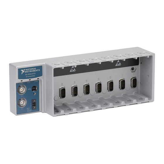
The NI cDAQ-9178 (eight slots) and NI cDAQ-9174 (four slots) USB chassis are designed for use with C Series I/O modules. The NI cDAQ-9178/9174 chassis is capable of measuring a broad range of analog and digital I/O signals and sensors using a Hi-Speed USB 2.0 interface. For module specifications, refer to the documentation included with your C Series I/O module(s) or go to ni.com/manuals... -
Page 4: Safety Guidelines
For additional support, refer to ni.com/support zone.ni.com Training Courses If you need more help developing an application with NI products, NI offers training courses. For more information, refer to ni.com/training Installing the Software Install NI-DAQmx. For more information, download the DAQ Getting Started Guide from ni.com/... -
Page 5: Installing The Ni Cdaq-9178/9174
Installing the NI cDAQ-9178/9174 NI cDAQ-9178/9174 Dimensions Figure 3 shows the dimensions of the NI cDAQ-9178/9174 chassis. 165.1 mm 19.0 mm (6.50 in.) (0.75 in.) 36.4 mm NI cDAQ-9178 NI CompactDAQ (1.43 in.) 88.1 mm POWER READY ACTIVE (3.50 in.) 59.6 mm... -
Page 6: Mounting The Ni Cdaq-9178/9174
NI 9901 Desktop Mounting Kit The NI 9901 desktop mounting kit includes two metal feet you can install on the sides of the NI cDAQ-9178/9174 chassis for desktop use. With this kit, you can tilt the NI cDAQ-9178/9174 chassis for convenient access to the I/O module connectors. - Page 7 These slots in the panel mount kit can be used with M4, M5, No. 8, or No.10 panhead screws. Figure 6 illustrates the panel dimensions and installation on the NI cDAQ-9178/9174 chassis. Refer to the documentation included with the panel mount kit for more detailed dimensions.
- Page 8 NI CompactDAQ POWER READY ACTIVE 88.1 mm (3.47 in.) INPUT 9-30 V 15 W MAX 48.4 mm 27.0 mm (1.91 in.) (1.06 in.) Figure 6. Panel Mount Dimensions and Installation on the NI cDAQ-9178/9174 NI cDAQ-9178/9174 User Guide and Specifications ni.com...
-
Page 9: Setting Up The Ni Cdaq-9178/9174
Complete the following steps to prepare the NI cDAQ-9178/9174 chassis for use: Before connecting the hardware, install the NI-DAQmx software. Note The NI-DAQmx software is included on the CD shipped with your kit and is available for download at . The documentation for NI-DAQmx is available after installation ni.com/support... -
Page 10: Understanding Led Indications
Definition Green Power supplied No power supplied Ready LED The Ready LED is lit when the NI cDAQ-9178/9174 chassis is ready for use. The color indicates whether the USB connection is Full-Speed or Hi-Speed. Table 2. Ready LED Definition Amber... -
Page 11: Using The Ni Cdaq-9178/9174
In most cases, the C Series I/O modules provide isolation from channel-to-earth ground. For more information about which C Series I/O modules are compatible with the NI cDAQ-9178/9174 chassis, refer to the KnowledgeBase document, C Series Modules Supported in the NI cDAQ-9178/9174 CompactDAQ. -
Page 12: Usb-Stc3
The PFI signals provide access to advanced features such as triggering, synchronization, and counter/timers. PFI signals are available through hardware-timed digital input and output modules installed in up to two chassis slots and through the two PFI terminals provided on the NI cDAQ-9178 chassis. Refer to the section for more information. - Page 13 • Counter n Internal Output The source also can be one of several other internal signals on your NI cDAQ-9178/9174 chassis. Refer to the Device Routing in MAX topic in the NI-DAQmx Help or the LabVIEW Help for more information.
- Page 14 Reference Trigger. Using an Analog Source Some C Series I/O modules can generate a trigger based on an analog signal. In NI-DAQmx, this is called the Analog Comparison Event. When you use an analog trigger source, the acquisition stops on the first rising or falling edge of the Analog Comparison Event signal, depending on the trigger properties.
-
Page 15: Analog Input Timing Signals
Using an Analog Source Some C Series I/O modules can generate a trigger based on an analog signal. In NI-DAQmx, this is called the Analog Comparison Event. When you use an analog trigger source, the internal sample clock pauses when the Analog Comparison Event signal is low and resumes when the signal goes high (or vice versa). - Page 16 If the AI Sample Clock rate is too fast to allow for 10 µs of padding, NI-DAQmx selects a conversion rate that spaces the AI Convert Clock pulses evenly throughout the sample. NI-DAQmx uses the same amount of padding for all the modules in the task.
-
Page 17: Getting Started With Ai Applications In Software
For more information, refer to the documentation included with your C Series I/O modules. You can run one hardware-timed (waveform) analog output task at a time on the NI cDAQ-9178/9174 chassis. At the same time, you can also run one or more software-timed (single-point or immediate) tasks. -
Page 18: Analog Output Data Generation Methods
Buffered Analog Output A buffer is a temporary storage in computer memory for generated samples. In a buffered generation, data is moved from a host buffer to the NI cDAQ-9178/9174 onboard FIFO before it is written to the C Series I/O modules. -
Page 19: Analog Output Triggering
• AI Start Trigger The source also can be one of several internal signals on the NI cDAQ-9178/9174 chassis. Refer to the Device Routing in MAX topic in the NI-DAQmx Help or the LabVIEW Help for more information. © National Instruments Corporation... - Page 20 Using an Analog Source Some C Series I/O modules can generate a trigger based on an analog signal. In NI-DAQmx, this is called the Analog Comparison Event, depending on the trigger properties. When you use an analog trigger source, the waveform generation begins on the first rising or falling edge of the Analog Comparison Event signal, depending on the trigger properties.
-
Page 21: Analog Output Timing Signals
NI cDAQ-9178/9174 chassis. You also can specify whether the samples are paused when ao/PauseTrigger is at a logic high or low level. Refer to the Device Routing in MAX topic in the NI-DAQmx Help or the LabVIEW Help for more information. -
Page 22: Minimizing Glitches On The Output Signal
Digital I/O To use digital I/O, insert a digital I/O C Series module into any slot on the NI cDAQ-9178/9174 chassis. The I/O specifications, such as number of lines, logic levels, update rate, and line direction, are determined by the type of C Series I/O module used. For more information, refer to the documentation included with your C Series I/O modules. -
Page 23: Digital Waveform Acquisition (Hardware-Timed Input)
• Counter n Internal Output The source also can be one of several other internal signals on your NI cDAQ-9178/9174 chassis. Refer to the Device Routing in MAX topic in the NI-DAQmx Help or the LabVIEW Help for more information. - Page 24 To use di/ReferenceTrigger with a digital source, specify a source and an edge. Either PFI or one of several internal signals on the NI cDAQ-9178/9174 chassis can provide the source. Refer to the Device Routing in MAX topic in the NI-DAQmx Help or the LabVIEW Help for more information.
-
Page 25: Digital Input Timing Signals
Using an Analog Source Some C Series I/O modules can generate a trigger based on an analog signal. In NI-DAQmx, this is called the Analog Comparison Event. When you use an analog trigger source, the acquisition stops on the first rising or falling edge of the Analog Comparison Event signal, depending on the trigger properties. - Page 26 NI-DAQmx Help or the LabVIEW Help for more information. The NI-DAQmx Help is available after installation from Start»All Programs»National Instruments» NI-DAQ»NI-DAQmx Help. To view the LabVIEW Help, select Help»Search the LabVIEW Help in LabVIEW. Alternately, to download the LabVIEW Help, go to ni.com/manuals...
-
Page 27: Getting Started With Di Applications In Software
You can configure lines on hardware-timed digital modules to detect rising or falling edges. When one or more of these lines sees the edge specified for that line, the NI cDAQ-9178/9174 samples all the lines in the task. The rising and falling edge lines do not necessarily have to be in the task. - Page 28 Buffered Digital Output A buffer is a temporary storage in computer memory for generated samples. In a buffered generation, data is moved from a host buffer to the NI cDAQ-9178/9174 onboard FIFO before it is written to the C Series I/O modules.
-
Page 29: Digital Output Triggering
If you are using an internal sample clock, you can specify a delay from the start trigger to the first sample. For more information, refer to the NI-DAQmx Help. The NI-DAQmx Help is available after installation from Start»All Programs» National Instruments»NI-DAQ»NI-DAQmx Help. - Page 30 • AI Start Trigger The source also can be one of several internal signals on the NI cDAQ-9178/9174 chassis. Refer to the Device Routing in MAX topic in the NI-DAQmx Help or the LabVIEW Help for more information. The NI-DAQmx Help is available after installation from Start»All Programs»National Instruments»...
-
Page 31: Getting Started With Do Applications In Software
NI cDAQ-9178/9174 chassis. You also can specify whether the samples are paused when do/PauseTrigger is at a logic high or low level. Refer to the Device Routing in MAX topic in the NI-DAQmx Help or the LabVIEW Help for more information. -
Page 32: Pfi
The NI cDAQ-9178/9174 has four general-purpose 32-bit counter/timers and one frequency generator. The general-purpose counter/timers can be used for many measurement and pulse generation applications. Figure 20 shows the NI cDAQ-9178/9174 Counter 0 and the frequency generator. All four counters on the NI cDAQ-9178/9174 are identical. -
Page 33: Counter Input Applications
Buffered Pulse Buffered Semi-Period Buffered Frequency Buffered Period Buffered Position Buffered Two-Signal Edge Separation Counter Input Applications The following sections list the various counter input applications available on the NI cDAQ-9178/9174: • Counting Edges • Pulse-Width Measurement • Pulse Measurement •... - Page 34 Source input after the counter is armed. The value of the counter is sampled on each active edge of a sample clock and stored in the FIFO. The USB-STC3 transfers the sampled values to host memory using a high-speed data stream. NI cDAQ-9178/9174 User Guide and Specifications ni.com...
- Page 35 If a counter is armed while the pulse is in the active state, it will wait for the next transition to the active state to begin the measurement. Refer to the following sections for more information about NI cDAQ-9178/9174 pulse-width measurement options: •...
- Page 36 FIFO of the last pulse width to complete. The USB-STC3 transfers the sampled values to host memory using a high-speed data stream. NI cDAQ-9178/9174 User Guide and Specifications ni.com...
- Page 37 You can calculate the high and low time of the Gate input by multiplying the period of the Source signal by the number of edges returned by the counter. Refer to the following sections for more information about NI cDAQ-9178/9174 pulse measurement options: •...
- Page 38 You can select whether to read the high pulse or low pulse first using the StartingEdge property in NI-DAQmx. Figure 28 shows an example of an implicit buffered pulse measurement.
- Page 39 The counter begins counting when it is armed. The arm usually occurs between edges on the Gate input. You can select whether to read the first active low or active high semi period using the CI.SemiPeriod.StartingEdge property in NI-DAQmx. © National Instruments Corporation NI cDAQ-9178/9174 User Guide and Specifications...
- Page 40 Default Counter/Timer Routing section. Frequency Measurement You can use the counters to measure frequency in several different ways. Refer to the following sections for information about NI cDAQ-9178/9174 frequency measurement options: • Low Frequency with One Counter • High Frequency with Two Counters •...
- Page 41 When measuring a large range of frequencies with two counters, you generate a long pulse using the signal to measure. You then measure the long pulse with a known timebase. The NI cDAQ-9178/9174 can measure this long pulse more accurately than the faster input signal.
- Page 42 You can route the signal to measure to the Source input of Counter 0, as shown in Figure 33. Assume this signal to measure has frequency fx. NI-DAQmx automatically configures Counter 0 to generate a single pulse that is the width of N periods of the source input signal.
- Page 43 For all frequency measurement methods, assume the following: is the frequency to be measured if no error is the known source or gate frequency measurement time (T) is the time it takes to measure a single sample © National Instruments Corporation NI cDAQ-9178/9174 User Guide and Specifications...
- Page 44 Take for example, measuring a 50 kHz signal. Assuming that the measurement times for the sample clocked (with averaging) and two counter frequency measurements are configured the same, Table 6 summarizes the results. NI cDAQ-9178/9174 User Guide and Specifications ni.com...
- Page 45 50 k and 5 M with a measurement time of 1 ms the error percentage is still close to 0.00125%. One of the disadvantages of a sample clocked frequency measurement is that the frequency to be © National Instruments Corporation NI cDAQ-9178/9174 User Guide and Specifications...
- Page 46 You can calculate the period of the Gate input by multiplying the period of the Source signal by the number of edges returned by the counter. Period measurements return the inverse results of frequency measurements. Refer to the Frequency Measurement section for more information. NI cDAQ-9178/9174 User Guide and Specifications ni.com...
- Page 47 You can choose to do either a single point (on-demand) position measurement or a buffered (sample clock) position measurement. You must arm a counter to begin position measurements. Refer to the following sections for more information about the NI cDAQ-9178/9174 position measurement options: •...
- Page 48 The counter supports two pulse encoders that have two channels—channels A and B. The counter increments on each rising edge of channel A. The counter decrements on each rising edge of channel B, as shown in Figure 40. NI cDAQ-9178/9174 User Guide and Specifications ni.com...
- Page 49 You can configure the rising or falling edge of the Aux input to be the active edge. You can configure the rising or falling edge of the Gate input to be the active edge. © National Instruments Corporation NI cDAQ-9178/9174 User Guide and Specifications...
- Page 50 Use this type of measurement to count events or measure the time that occurs between edges on two signals. This type of measurement is sometimes referred to as start/stop trigger measurement, second gate measurement, or A-to-B measurement. Refer to the following sections for more information about the NI cDAQ-9178/9174 edge-separation measurement options: •...
-
Page 51: Counter Output Applications
The following sections list the various counter output applications available on the NI cDAQ-9178/9174: • Simple Pulse Generation • Pulse Train Generation • Frequency Generation • Frequency Division • Pulse Generation for ETS © National Instruments Corporation NI cDAQ-9178/9174 User Guide and Specifications... - Page 52 Simple Pulse Generation Refer to the following sections for more information about the NI cDAQ-9178/9174 simple pulse generation options: • Single Pulse Generation • Single Pulse Generation with Start Trigger Single Pulse Generation The counter can output a single pulse. The pulse appears on the Counter n Internal Output signal of the counter.
- Page 53 This function generates a train of pulses with programmable frequency and duty cycle for a predetermined number of pulses. With NI cDAQ-9178/9174 counters, the primary counter generates the specified pulse train and the embedded counter counts the pulses generated by the primary counter.
- Page 54 You also can use the Gate input of the counter as a Pause Trigger (if it is not used as a Start Trigger). The counter pauses pulse generation when the Pause Trigger is active. NI cDAQ-9178/9174 User Guide and Specifications ni.com...
- Page 55 Buffered Pulse Train Generation NI cDAQ-9178/9174 counters can use the FIFO to perform a buffered pulse train generation. This pulse train can use implicit timing or sample clock timing. When using implicit timing, the pulse idle time and active time changes with each sample you write. With sample clocked timing, each sample you write updates the idle time and active time of your generation on each sample clock edge.
- Page 56 Source Figure 52. Finite Buffered Sample Clocked Pulse Train Generation There are several different methods of continuous generation that control what data is written. These methods are regeneration, FIFO regeneration, and non-regeneration modes. NI cDAQ-9178/9174 User Guide and Specifications ni.com...
- Page 57 D. In this case, Frequency Output is low for (D + 1)/2 cycles and high for (D – 1)/2 cycles of the Frequency Output Timebase. © National Instruments Corporation NI cDAQ-9178/9174 User Guide and Specifications...
- Page 58 Nyquist frequency of the system. Figure 55 shows an example of pulse generation for ETS; the delay from the trigger to the pulse increases after each subsequent Gate active edge. NI cDAQ-9178/9174 User Guide and Specifications ni.com...
-
Page 59: Counter Timing Signals
All counter timing signals can be filtered. In this section, n refers to the NI cDAQ-9178/9174 Counter 0, 1, 2, or 3. For example, Counter n Source refers to four signals—Counter 0 Source (the source input to Counter 0), Counter 1 Source (the source input to Counter 1), Counter 2 Source (the source input to Counter 2), or Counter 3 Source (the source input to Counter 3). - Page 60 Counter n Gate input: • Any PFI terminal • AI Reference Trigger (ai/ReferenceTrigger) • AI Start Trigger (ai/StartTrigger) • AO Sample Clock (ao/SampleClock) • DI Sample Clock (di/SampleClock) • DI Reference Trigger (di/ReferenceTrigger) NI cDAQ-9178/9174 User Guide and Specifications ni.com...
- Page 61 Gate signal when it is armed. Counter output operations can use the arm signal in addition to a start trigger. © National Instruments Corporation NI cDAQ-9178/9174 User Guide and Specifications...
- Page 62 Counter n Sample Clock. If the NI cDAQ-9178/9174 receives a Counter n Sample Clock when the FIFO is full, it reports an overflow error to the host software.
-
Page 63: Default Counter/Timer Routing
You can use these defaults or select other sources and destinations for the counter/timer signals in NI-DAQmx. Refer to Connecting Counter Signals in the NI-DAQmx Help or the LabVIEW Help for more information about how to connect your signals for common counter measurements and generations. -
Page 64: Other Counter Features
Prescaling allows the counter to count a signal that is faster than the maximum timebase of the counter. The NI cDAQ-9178/9174 offers 8X and 2X prescaling on each counter (prescaling can be disabled). Each prescaler consists of a small, simple counter that counts to eight (or two) and rolls over. This counter can run faster than the larger counters, which simply count the rollovers of this smaller counter. -
Page 65: Digital Routing And Clock Generation
NI cDAQ-9178 chassis PFI terminals. • Routes and generates the main clock signals for the NI cDAQ-9178/9174 chassis. To determine the signal routing options for C Series I/O modules installed in the NI cDAQ-9178/9174 chassis, refer to the Device Routes tab in MAX. -
Page 66: Clock Routing
Clock Routing Figure 59 shows the clock routing circuitry of the NI cDAQ-9178/9174 chassis. 80 MHz Timebase Onboard 80 MHz ÷ 20 MHz Timebase Oscillator ÷ 100 kHz Timebase Figure 59. NI cDAQ-9178/9174 Clock Routing Circuitry 80 MHz Timebase You can use the 80 MHz Timebase as the Source input to the 32-bit general-purpose counter/timers. -
Page 67: Specifications
Specifications These specifications are for the NI cDAQ-9178/9174 chassis only. These specifications are typical at 25 °C unless otherwise noted. For the C Series I/O module specifications, refer to the documentation for the C Series I/O modules you are using. -
Page 68: General-Purpose Counter/Timers
FIFO...............Dedicated 127-sample FIFO Frequency Generator Number of channels ..........1 Base clocks ............10 MHz, 20 MHz, 100 kHz Divisors ..............1 to 16 (integers) Base clock accuracy..........50 ppm Output is available on any PFI terminal. NI cDAQ-9178/9174 User Guide and Specifications ni.com... -
Page 69: Module Pfi Characteristics
Timing output sources..........Many analog input, analog output, counter, digital input, and digital output timing signals Timing input frequency..........0 to 20 MHz Timing output frequency........0 to 20 MHz Chassis PFI Characteristics (NI cDAQ-9178 Only) Max input or output frequency ......1 MHz Minimum Maximum Positive Going Threshold Voltage 1.43... -
Page 70: Module I/O States
The chassis may revert the input/output of the modules to its power-on state when the USB cable is removed. Power Requirements You must use a National Electric Code (NEC) Class 2 power source with the NI cDAQ-9178/9174 chassis. Note Some C Series I/O modules have additional power requirements. For more information about C Series I/O module(s) power requirements, refer to documentation included with the C Series I/O module(s). -
Page 71: Safety
, search by model number or product line, and click the appropriate link in the certification Certification column. Environmental The NI cDAQ-9178/9174 chassis is intended for indoor use only. For outdoor use, mount the system in a suitably rated enclosure. Operating temperature (IEC-60068-2-1 and IEC-60068-2-2) ....–20 to 55 °C Storage temperature (IEC-60068-2-1 and IEC-60068-2-2) ....–40 to 85 °C... -
Page 72: Safety Standards
NI recognizes that eliminating certain hazardous substances from our products is beneficial not only to the environment but also to NI customers. For additional environmental information, refer to the NI and the Environment Web page at . This page contains the environmental regulations and directives with which ni.com/environment... -
Page 73: Where To Go For Support
Thailand 662 278 6777, Turkey 90 212 279 3031, United Kingdom 44 (0) 1635 523545 National Instruments, NI, ni.com, and LabVIEW are trademarks of National Instruments Corporation. Refer to the Terms of Use section on ni.com/legal for more information about National Instruments trademarks. Other product and company names mentioned herein are trademarks or trade names of their respective companies.
Need help?
Do you have a question about the cDAQ-9178 and is the answer not in the manual?
Questions and answers