Table of Contents
Advertisement
Quick Links
See also:
Service Manual
Advertisement
Table of Contents

Related Manuals for Spectra Precision FOCUS 35


Summary of Contents for Spectra Precision FOCUS 35
- Page 1 User Guide Spectra Precision® FOCUS® 35 Total Station Version 1.05 Revision D June 2017 Part Number 77781035...
- Page 2 This is the June 2017 release version 1.05 of the Spectra Precision – Reorient or relocate the receiving antenna. FOCUS 35 Total Station User Guide, P/N 77701035. It applies to the – Increase the separation between the equipment and the receiver.
-
Page 3: Important Information
Important Information Before using the Spectra Precision® FOCUS® 35 total station, make sure that you understand this user guide, as well as all equipment and job site safety requirements. Safety Information • Instruments and original accessories from Spectra Precision must only be used for the intended purpose. -
Page 4: Laser Safety Questions
Phone (937) 233-8921 ext 824 or (800) 538-7800 Fax (937) 233-9661 Spectra Precision FOCUS 35 Total Station The Spectra Precision FOCUS 35 Total Station is a CLASS 3R LASER PRODUCT and contains different light sources. Distance Measurement and Laser Pointer The Distance Measuring Unit in reflectorless mode and in Laser Pointer mode produces visible Laser light emerging at the centre of the telescope objective. -
Page 5: Tracklight
WARNING – The use of Laser Class 3R equipment can be dangerous for the eyes. The risk for eye damage is minimized through the radiation limit of 5 mW (FOCUS 35 at 660 nm). Do not stare directly into the beam. -
Page 6: Lockngo Tracker
- Do not immerse the battery in water. - Do not use or store the battery inside a vehicle during hot weather. - Do not drop or puncture the battery. - Do not open the battery or short-circuit its contacts. FOCUS 35 TOTAL STATION USER GUIDE... -
Page 7: Environmental Information
- Do not charge or use the battery if it appears to be damaged or leaking. - Charge the lithium-ion battery only in a Spectra Precision product that is specified to charge it. Be sure to follow all instructions that are provided with the battery charger. -
Page 8: Table Of Contents
Laser Information ..........36 Spectra Precision FOCUS 35 Total Station ....... . .37 Setup . - Page 9 Spectra Precision Survey Pro Version ........47...
- Page 10 Spectra Precision 360 Degree Prism ........
-
Page 11: Introduction
For more information about this product, please visit our web site at www.spectraprecision.com. Product Registration To obtain information regarding updates and new products, contact your local Spectra Precision distributor, or go to the Spectra Precision web site, www.spectraprecision.com. FOCUS 35 TOTAL STATION USER GUIDE... -
Page 12: Inspection, Care, And Maintenance
C H A P T E R Inspection, Care, and Maintenance In this chapter: Inspecting the Container Instrument Case Care and Maintenance Transporting the Instrument Servicing FOCUS 35 TOTAL STATION USER GUIDE... -
Page 13: Instrument Case
Inspect the shipping container. If the container arrives in poor condition, examine the equipment for visible damage. If damage is found, immediately notify the carrier and your Spectra Precision sales representative. Keep the container and the packing material for the carrier to inspect. - Page 14 ** Optional accessory item CAUTION – If the instrument is equipped with an optional DIN adapter for DIN tribrach, the DIN tribrach must be removed before the instrument is placed in the instrument case. FOCUS 35 TOTAL STATION USER GUIDE...
-
Page 15: Instrument Versions
FOCUS 35 RX 5" FOCUS 35 LockNGo 1" FOCUS 35 LockNGo 2" FOCUS 35 LockNGo 3" FOCUS 35 LockNGo 5" FOCUS 35 StepDrive 1" FOCUS 35 StepDrive 2" FOCUS 35 StepDrive 3" FOCUS 35 StepDrive 5" FOCUS 35 TOTAL STATION USER GUIDE... -
Page 16: Care And Maintenance
If an unauthorized person opens the instrument cover, the function of the instrument is not guaranteed and the warranty is invalidated. The Spectra Precision FOCUS 35 Total Station is designed and tested to withstand field conditions, but like all precision instruments, it requires care and maintenance. -
Page 17: Applying A Screen Protector For The Face 1 Screen (If Fitted)
Servicing Note – There are no user-serviceable parts on the Spectra Precision FOCUS 35 Total Station. Spectra Precision recommends that you take the instrument to an authorized service center for service and calibration once a year. -
Page 18: Getting Started
C H A P T E R Getting Started In this chapter: Power Supply Instrument Description Connecting the Instrument to an Office Computer Laser Information FOCUS 35 TOTAL STATION USER GUIDE... -
Page 19: Battery Safety And Environment Information
- Do not charge or use the battery if it appears to be damaged or leaking. - Charge the lithium-ion battery only in a Spectra Precision product that is specified to charge it. Be sure to follow all instructions that are provided with the battery charger. -
Page 20: Checking The Instrument Battery Power Supply
3 – Getting Started Checking the Instrument Battery Power Supply To check the power supply in the Spectra Precision FOCUS 35 Total Station battery using the built in battery gauge, press the button on the side of the battery: Button Power gauge When you press the button, four LEDs on the battery show the power level. - Page 21 3 – Getting Started • Charge the battery before using the total station if the equipment has been stored for longer than six months. Via country specific Radio Battery adapter to mains power AC/DC Converter DC Input FOCUS 35 TOTAL STATION USER GUIDE...
-
Page 22: Inserting The Main Battery
3 – Getting Started Inserting the Main Battery The Spectra Precision FOCUS 35 Total Station internal battery fits into the battery compartment on the side of the instrument. This battery can easily be removed and replaced. To insert the battery: Press gently on the battery release button to open the battery compartment door. -
Page 23: Inserting The Face 1 Battery (If Available)
3 – Getting Started Inserting the Face 1 Battery (if Available) On some Spectra Precision FOCUS 35 Total Station models a second battery fits into the Face 1 battery compartment. This battery can easily be removed and replaced. To insert the battery: Press gently on the two battery release buttons on either side of the compartment to open the battery compartment door. -
Page 24: Suspend Mode
To resume, press the power button for about one second, until you hear one single beep. The internal support module is always charged when the instrument is powered on. If you leave the Spectra Precision FOCUS 35 Total Station idle, it goes into suspend mode after 120 minutes by default. -
Page 25: Instrument Description
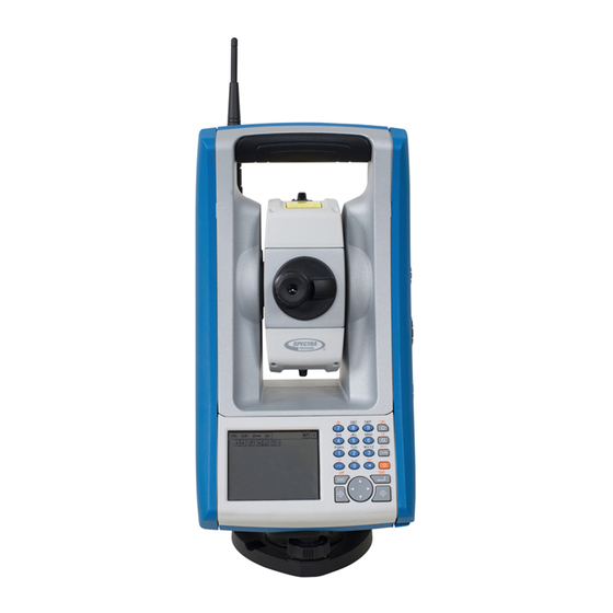
This section describes the instrument controls. Spectra Precision recommends that you take some time to familiarize yourself with the names and the locations of the controls. The following image shows the Operator’s view of the Spectra Precision FOCUS 35 Total Station. ❶... - Page 26 3 – Getting Started The following is the Front view of the Spectra Precision FOCUS 35 Total Station. ❶ ❻ ❺ ❷ ❹ ❸ ❼ Item Description ❶ Radio antenna Radio antenna not required in StepDrive and LockNGo models. ❷...
-
Page 27: Optical Plummet
To focus the crosshair, rotate the eye-piece. • • To focus the optical plummet to the ground, push in or pull out the optical plummet. For information on how to adjust the optical plummet, see Optical Plummet, page FOCUS 35 TOTAL STATION USER GUIDE... -
Page 28: Trigger Key
The image shows the Control Unit Face1. ❶ ❷ ❸ Item Description ❶ Quick Shot Menu ❷ Measurement 1 ❸ Measurement 2 FOCUS 35 TOTAL STATION USER GUIDE... -
Page 29: Operating System
Control Functions Control Unit Face1 ® In addition to data entry and the standard Windows functions, the Control Unit has a number of control functions that are Spectra Precision specific. These functions are described in the table below. Keys Function... - Page 30 Follow the prompts on the screen. Disabling the Touch Screen + B [S] to disable it. To enable the touch screen To clean the touch screen during a survey, press + B. again, press FOCUS 35 TOTAL STATION USER GUIDE...
-
Page 31: Control Unit Face2
Control Unit Face2 The Face2 control unit is a graphical display with a built-in backlight and four control buttons. Function Description Change Face Scroll Up Scroll Down Enter FOCUS 35 TOTAL STATION USER GUIDE... -
Page 32: Telescope Lens Rain Cover / Sun Shade
Fit the objective rain cover to the Face1 side of the instrument with the shield at the top of the objective. CAUTION – Dust and rain can have an effect on the distance measurements, please keep objective front lens and the targeting prism clean and use the objective rain cover. FOCUS 35 TOTAL STATION USER GUIDE... -
Page 33: Transferring Data Files
You can also use the Explore feature in either program to move files or programs from your computer to your device. ActiveSync is already integrated into the operating system on the Spectra Precision FOCUS 35 Total Station. However, you must install ActiveSync or WMDC depending on your computers operating system. -
Page 34: Setting Up And Running Activesync Technology
3 – Getting Started Setting Up and Running ActiveSync technology Please use the Hirose-USB cable to connect the Spectra Precision FOCUS 35 Total Station with a USB port of your computer. The instrument will switch on automatically. Note – Microsoft ActiveSync tecnology or the Windows Mobile Device Center will start automatically, depending on the operating system that is installed on your computer. - Page 35 Click in the dialog. Setup Complete ActiveSync opens. To view the files on the Instrument, click the icon. The file structure looks and functions Explore the same as Windows Explorer on your computer. FOCUS 35 TOTAL STATION USER GUIDE...
-
Page 36: Disconnecting Activesync
Tip – You have to wait a few seconds until the next screen appears. and then remove the cable: For more information about ActiveSync, refer to the help or visit the Microsoft website. Laser Information For more information, see Laser Safety, page FOCUS 35 TOTAL STATION USER GUIDE... -
Page 37: Spectra Precision Focus 35 Total Station
3 – Getting Started Spectra Precision FOCUS 35 Total Station The Spectra Precision FOCUS 35 distance measuring unit and Laser Pointer has been tested and complies with the regulations for a CLASS 3R LASER PRODUCT. ❶ ❷ Item Description ❶... - Page 38 3 – Getting Started Location of Laser warning label on a Spectra Precision FOCUS 35 Total Station The laser warning label is located on the top of the distance measuring unit. Distance Measurement Unit and Laser Pointer warning label: FOCUS 35 TOTAL STATION USER GUIDE...
- Page 39 3 – Getting Started Location of Laser aperture label on a Spectra Precision FOCUS 35 Total Station The laser aperture label is located on one side of the telescope close to the objective. Laser aperture label: FOCUS 35 TOTAL STATION USER GUIDE...
-
Page 40: Setup
In this chapter: Setup Starting the Instrument Security Instrument Adjustment and Calibration LockNGo Tracker Measuring the Instrument Height Pre Measurement Check List Connecting to an External Data Collector FOCUS 35 TOTAL STATION USER GUIDE... -
Page 41: Setup
4 – Setup Setup An instrument setup with good measuring stability will increase the precision in the measurement result and allow you to utilize the measurement precision of the Spectra Precision FOCUS 35 Total Station to its full extent. Setup Stability When an instrument is setup it is important to consider the following: 1. -
Page 42: Starting The Instrument
Robotic mode. • When the Windows CE operating system starts, select your field software from the start menu. Please refer to your Spectra Precision Survey field application documentation for supplementary information. FOCUS 35 TOTAL STATION USER GUIDE... -
Page 43: Starting And Settings Via Face1 Control Unit (If Fitted)
Note – StepDrive motor system and Focus System are already usable at this phase. Note – If you are using the Spectra Precision Layout Pro software, refer to that product’s User Guide for information on using the FOCUS 35 total station. -
Page 44: First Steps In Spectra Precision Survey Pro Software
4 – Setup First Steps in Spectra Precision Survey Pro software Spectra Precision recommends spending some time reading the Spectra Precision Survey Pro User Guide to learn details of the application program. This subchapter describes a brief overview. Quick Shot Menu After confirming the Level Bubble menu the screen shows the Quick Shot menu. -
Page 45: Lookup And Register Software
Lookup and register Software Screen Actions and Comments Registration Modules menu After the initial start of Spectra Precision Survey Pro, the following menu will appear. Please select Register Modules and enter your registration code(s). How to enter codes Please use the keyboard on the screen to enter registration code. - Page 46 Main Menu Spectra Precision Survey Pro Select menu File. The appropriate menu items appear on the screen - e.g. Open /New. Menu to work with jobs Select a file with Open or create a New Job with New. FOCUS 35 TOTAL STATION USER GUIDE...
-
Page 47: Spectra Precision Survey Pro Version
Main Menu File About Select menu File and menu element About and the software version appears on the screen. Survey Pro Version Press the ESC button and the program will return automatically to the Main Menu. FOCUS 35 TOTAL STATION USER GUIDE... - Page 48 Select instrument Settings by tapping on this icon. Menu for Settings Navigate to Lights via drop down menu or toggle through the submenus with D key left or right. Menu for Lights Settings Make selections and confirm the settings. FOCUS 35 TOTAL STATION USER GUIDE...
-
Page 49: Starting And Settings Via Face2 Control Unit
– N - Leveling menu – O - Status for battery and external power supply status – P - Instrument Settings Note – StepDrive motor system and FOCUS System are usable while the Instrument Status menu shows Waiting. FOCUS 35 TOTAL STATION USER GUIDE... - Page 50 O key press the Power Supply Menu. Power Supply - external source Menu shows the voltage of the source. Leave the menu with P press. Power Supply Int.Bat. 6% low >Ext. Bat. 12.4V ok FOCUS 35 TOTAL STATION USER GUIDE...
-
Page 51: Security
By default, the PIN code is set to 0000. With this code set, security is not activated and the user is not prompted to enter the PIN code at start up. The user can activate or change the PIN code (see following page). FOCUS 35 TOTAL STATION USER GUIDE... -
Page 52: Activating Or Changing The Pin Code
O to enter the PUK code digit by digit—press P to accept each digit. 4. Once all valid digits have been entered, press P. The FOCUS 35 instrument is unlocked, the PIN code is reset to 0000 and the security PIN code is deactivated. -
Page 53: Face2 Display While Using Spectra Precision Survey Pro In Different Instrument Versions
4 – Setup Face2 Display while using Spectra Precision Survey Pro in different Instrument Versions StepDrive and LockNGo versions: If the field software at Control Unit Face1 is started, the field software controls the Face2 display. Screen Actions and Comments... - Page 54 Adjust the contrast by pressing N or O. Confirm the selection with P. F2 Contrast Contrast range: 0 - 256 Contrast: Note – Setting function for brightness and contrast is available on every F2 menu. FOCUS 35 TOTAL STATION USER GUIDE...
-
Page 55: Main Menu Face2 - Information And Settings
Exit Radio Parameter Level bubble Instrument details The Main Menu is structured as follows Content See page... Exit Radio Parameter page 56 Level bubble page 56 Instrument details page 57 Service menu page 58 FOCUS 35 TOTAL STATION USER GUIDE... - Page 56 When last digit of Network ID is confirmed, the system jumps back to the Main Menu. Radio channel range: 1- 30 Network ID range: 0 - 255 Level Bubble These details are already described in Leveling, page FOCUS 35 TOTAL STATION USER GUIDE...
- Page 57 Instrument Details and press P. Main Menu Exit Radio Parameter Level Bubble Instrument Details Leave the menu by pressing the P key. Instrument Details Instrument Details FOCUS 35 Robotic 2“ Your definition Serial: 87000002 FWVer: R 1.4.0 FOCUS 35 TOTAL STATION USER GUIDE...
- Page 58 61 Radio configuration page 62 Next Service Date page 62 Note – The Service Menu is hidden—please contact your Spectra Precision Reseller for instructions on how to access this option. The Service Menu enables the following: • USB interface settings •...
- Page 59 Tip – Please make sure that the default setting USB Interface for Customer is Always Off. USB Interface Exit Tip – If the FOCUS 35 total station needs a Always Off firmware upgrade, the USB interface setting Always On must be set to Always On to complete the Temporary On firmware upgrade.
- Page 60 WARNING – Both values for External EDM Ext. EDM Frequency Calibration influence the measured distance Ext. EDM Calibration directly! Therefore, they must have been Drive Mode determined by means of an accurate external calibration. FOCUS 35 TOTAL STATION USER GUIDE...
- Page 61 Drive Mode press P. Normal: This mode is the default mode. Mode is suitable Drive mode Exit for all instrument mounts. Normal Fast: Fast Mode can be a choice for instrument mount on tripods. FOCUS 35 TOTAL STATION USER GUIDE...
- Page 62 If the Service date is already expired the program offers the possibility to postpone the Next Service Next Service date date (today plus three months). This change will be Today: 01.09.2011 logged internally. Service: 01.12.2011 FOCUS 35 TOTAL STATION USER GUIDE...
-
Page 63: Instrument Adjustment And Calibration
Routinely on a periodic basis (Monthly, weekly etc.) • Spectra Precision also recommends that the operator keep a record of the dates and values measured so that any gross changes can easily be detected. Gross changes can indicate the need for a check by an approved service center. -
Page 64: Optical (Ha/Va) Collimation And Trunnion Axis Tilt
In this way the Spectra Precision FOCUS 35 Total Station will always provide accurate measurements. - Page 65 Main Menu Spectra Precision Survey Pro Select instrument Settings by tapping on this icon. Settings Collimation Navigate to Collimation via drop down menu or toggle through the submenus with D key left or right. Select the appropriate adjustment. FOCUS 35 TOTAL STATION USER GUIDE...
- Page 66 Make the measurements per the displayed information and confirm and store the values. Optical Collimation / Trunnion Axis Decide per the displayed information for trunnion axis tilt collimation or confirm and store the new values for optical collimation. FOCUS 35 TOTAL STATION USER GUIDE...
- Page 67 Make sure to measure with the stated conditions. Compensator Collimation start scree Make the measurements per the displayed information. During the process the instrument should be free from vibration and untouched by the user. FOCUS 35 TOTAL STATION USER GUIDE...
-
Page 68: The Laser Pointer
The Laser Pointer The Spectra Precision FOCUS 35 Total Station uses a red laser beam to measure and as a Laser Pointer. The Laser Pointer is coaxial with the line of sight of the telescope. If the instrument is well adjusted, the red Laser Pointer coincides with the line of sight. -
Page 69: Adjusting The Laser Beam
1. Pull out the two plugs from the adjustment ports of the telescope housing: The image shows the Laser beam adjustment ports. ❷ ❶ Item Description ❶ Vertical pointer adjustment port ❷ Horizontal pointer adjustment port FOCUS 35 TOTAL STATION USER GUIDE... - Page 70 4 – Setup 2. To correct the vertical position of the laser spot, insert the allen key into the vertical adjustment port and turn it as shown: Counter clockwise = up Clockwise = down FOCUS 35 TOTAL STATION USER GUIDE...
- Page 71 5. Refit the plugs in the adjustment holes. Make sure that the plugs are correctly fitted for proper sealing against the cover. CAUTION – To keep out moisture and dust, make sure that the plugs are correctly fitted in the adjustment ports. FOCUS 35 TOTAL STATION USER GUIDE...
-
Page 72: Optical Plummet
When one screw is adjusted the opposite screw must be adjusted equally in the reverse direction, in order to keep the correct tension on the optics. Do not overtighten the screws, this might damage the optics. FOCUS 35 TOTAL STATION USER GUIDE... -
Page 73: Tribrach Circular Level
1. Level the instrument with the electronic instrument bubble. 2. Remove the instrument from the tribrach. 3. Use the provided adjustment key and adjust the bubble with the three bubble screws. The bubble must be centered. FOCUS 35 TOTAL STATION USER GUIDE... - Page 74 When one screw is adjusted the two opposite screw must be adjusted equally in the reverse direction, in order to keep the correct tension on the Circular level. Do not overtighten the screws. Circular Level adjustment: FOCUS 35 TOTAL STATION USER GUIDE...
-
Page 75: Measuring The Instrument Height
Instrument height marks: ❶ ❷ When the Spectra Precision Survey Pro is running, the software has additional functions that reduce the bottom mark measurement to the required vertical instrument height to the trunnion axis, see image below and the following paragraph. - Page 76 (Hc). The constant from the bottom mark to the top mark (0.158 m/0.518 ft) is added to the Hc to obtain the vertical instrument height from the ground mark to the trunnion axis (Ih). For more information, refer to the Spectra Precision Survey Pro documentation.
-
Page 77: Pre Measurement Check List
Spectra Precision FOCUS 35 Total Station. The controller can be connected to the Spectra Precision FOCUS 35 Total Station via cable or via radio. Connecting with Cable - Instrument Version StepDrive and... - Page 78 4 – Setup The image shows an External controller connected to the Spectra Precision FOCUS 35 Total Station with cable for StepDrive and LockNGo measurements. FOCUS 35 TOTAL STATION USER GUIDE...
-
Page 79: Connecting With Radio - Instrument Versions Robotic And Rx
Connecting with Radio - Instrument Versions Robotic and The data collector is connected directly to the instrument via the internal in radio. The image shows an External Data Collector connected to the Spectra Precision FOCUS 35 Total Station using the radio for robotic measurements. -
Page 80: Instrument Operation Methods
C H A P T E R Instrument Operation Methods In this chapter: Introduction Conventional Measurements with StepDrive Motor System LockNGo Measurement GeoLock Technology Robotic Measurement FOCUS 35 TOTAL STATION USER GUIDE... -
Page 81: Introduction
GeoLock Technology GeoLock™ technology is a feature of the Spectra Precision Survey Pro software that allows a robotic total station to perform an aided search for an optical target using an initial GPS position. The technology greatly reduces the time to locate and lock onto a target. -
Page 82: Robotic Measurement
5 – Instrument Operation Methods The Spectra Precision GeoLock technique combines a GNSS position with the FOCUS 35 robotic total station and the robotic roving operator. The remote instrument can then be directed towards the robotic roving operator using the GNSS position and a subsequent search is quickly performed to reacquire the target at the robotic rover. -
Page 83: Instrument Technology
Instrument Technology In this chapter: Angle Measuring Technology Distance Measuring Technology Tracklight StepDrive Motor System and Focus System LockNGo Tracking Technology Power Management Power Supply External Communication FOCUS 35 TOTAL STATION USER GUIDE... -
Page 84: Angle Measuring Technology
Correction for Trunnion Axis, page Correction for Mislevelment The Spectra Precision FOCUS 35 Total Station automatically corrects for mislevelments up to ±5.5’. The instrument warns the operator immediately of any mislevelments in excess of ±5.5’(±0.1 grads). Corrections for the horizontal angle, vertical angle, and slope distance are calculated in the field application software and applied to all measurements. -
Page 85: Correction For Collimation Errors
Spectra Precision FOCUS 35 Total Station with LockNGo Tracker A Spectra Precision FOCUS 35 Total Station with LockNGo capability can automatically lock and track a prism target as it moves. Pointing errors caused by slight misalignment of the instrument’s tracker have a similar effect to the HA and VA Collimation errors as detailed above. -
Page 86: Correction For Trunnion Axis
Trunnion axis tilt error In the Spectra Precision FOCUS 35 Total Station, perform a pre-measurement trunnion axis tilt test to determine the trunnion axis tilt error. Angular measurements are observed in both instrument faces, the trunnion axis tilt error is calculated, and the respective correction value is stored in the instrument. -
Page 87: Averaging Measurements To Reduce Sighting Errors
• Distance Measuring Technology Spectra Precision FOCUS 35 Total Stations are equipped with a combined distance unit. This means that the instrument can measure to a prism or to normal surfaces (reflectorless mode). The laser distance unit is based on the phase comparison method. The distance unit is coaxial with the line of sight and transmits an intensity modulated optical measuring beam that is reflected by a prism or scattered by a natural surface on which the beam is directed. -
Page 88: Beam Divergence
A smaller measuring area has advantages when measuring tight corners and vertices at close range. When observing measurements to a tight corner, the distance meter beam divergence introduces a range error caused by the size of the sampling area. FOCUS 35 TOTAL STATION USER GUIDE... - Page 89 Do the following: 1. Measure two points on the face of the building. 2. Aim the instrument at the corner to store the correct horizontal and vertical angle. FOCUS 35 TOTAL STATION USER GUIDE...
- Page 90 Offset measurement: Point 1 Point 2 Point 3 With offset measurements, you can accurately measure difficult locations in reflectorless mode and eliminate beam divergence errors. For more information, refer to the field application software documentation. FOCUS 35 TOTAL STATION USER GUIDE...
-
Page 91: Tracklight
Do not use the Laser Pointer as an aid when searching for prisms, the reflected light can dazzle your eyes. The reflected light will not damage your eyes, but might be uncomfortable, see also Laser Safety, page FOCUS 35 TOTAL STATION USER GUIDE... -
Page 92: Stepdrive Motor System And Focus System
6 – Instrument Technology StepDrive Motor System and Focus System Spectra Precision FOCUS 35 Total Station is equipped with a StepDrive motor system to position the instrument and the telescope and a servo drive to focus the telescope. Due to the instrument accuracy it is important to use a high quality tripod and tribrach. It is also important to set up the tripod in a position for best stability, as shown. -
Page 93: Stepdrive
LockNGo Tracker technology for robotic surveying, see image below. Please see also Settings for Drive Mode:, page Position StepDrive motion knobs: ❶ Down ❷ Right Left Item Description ❶ Vertical motion knob ❷ Horizontal motion knob FOCUS 35 TOTAL STATION USER GUIDE... -
Page 94: Focus System
The focus knob is connected to a servo motor that is built into the telescope. When you turn the focus motion knob, the servo motor adjusts the focusing lens. Focus motion knob FOCUS 35 TOTAL STATION USER GUIDE... -
Page 95: Lockngo Tracking Technology
6 – Instrument Technology LockNGo Tracking Technology The Spectra Precision FOCUS 35 Total Station is equipped with an image based tracking system, which is used for robotic or conventional measurements to lock onto and track a prism. LockNGo tracking technology controls the instrument StepDrive motor systems and aims the instrument correctly towards the target. -
Page 96: Instrument
Note – During Suspend Mode the Trigger key LED will flash once every five seconds. Robotic configuration A separate control unit is via cable or radio connected with the instrument. For starting the instrument see Instrument, page FOCUS 35 TOTAL STATION USER GUIDE... -
Page 97: Power Supply
External Power Supply The Spectra Precision FOCUS 35 Total Station has one external port in the base of the instrument for communication and for external power supply. External power can be provided by a car battery with an appropriate cable. -
Page 98: External Communication
6 – Instrument Technology External Communication The communication port on the base of the Spectra Precision FOCUS 35 Total Station can be used for external communications to a computer or data collector. CAUTION – Use only the gray cables with 6-pin Hirose connectors from Spectra Precision when connecting a cable to the instrument. -
Page 99: Accessories And Options
Accessories and Options In this chapter: Rod and Prisms Robotic Components Cables for External Power Supply and Data Transfer Control Unit Screen Protector Telescope Accessories Transport Case Accessories FOCUS 35 TOTAL STATION USER GUIDE... -
Page 100: Rod And Prisms
Spectra Precision standard rod. Note – The FOCUS 35 total station is a passive tracking device that allows users to measure and track a variety of prisms. Necessary prism constants and quality checks are recommended to maintain high-accuracy measurement results. - Page 101 7 – Accessories and Options The 360 Degree prism including height adapter: FOCUS 35 TOTAL STATION USER GUIDE...
-
Page 102: Robotic Components
Radio implemented in external CU like Spectra Precision Ranger (radio option) • Separate external radio used with Spectra Precision Nomad and Spectra Precision Recon consists of Controller radio and cable - see picture below. The Robotic Rod with Nomad and external Radio:... - Page 103 External radio 2.4 GHz Global: Indicator LED Battery COM Port For information regarding charging of the battery, see Charging the Instrument and the Radio Batteries, page CAUTION – Always remove the battery from the external radio after use. FOCUS 35 TOTAL STATION USER GUIDE...
- Page 104 Attaching the Battery To fit the battery to the radio: 1. Fit the battery to the battery holder. 2. Push the battery downwards until the catch clicks in place. Click Click 3. 3. 2. 2. FOCUS 35 TOTAL STATION USER GUIDE...
- Page 105 7 – Accessories and Options Detaching the Battery To remove the battery from the radio: 1. Press the catch towards the radio. 2. Slide the battery upwards. 3. Pull the battery away from the battery holder: 3. 3. FOCUS 35 TOTAL STATION USER GUIDE...
- Page 106 7 – Accessories and Options Cable between Data Collector and radio FOCUS 35 TOTAL STATION USER GUIDE...
-
Page 107: Cables For External Power Supply And Data Transfer
Cable from the instrument to PC with Hirose 6 pin and USB-A plug. Cable - 2.5 m (8 ft): Cable from the instrument to USB flash card memory with Hirose 6 pin and USB-A socket. Cable - 0.18 m (0.6 ft): FOCUS 35 TOTAL STATION USER GUIDE... -
Page 108: Control Unit Screen Protector
7 – Accessories and Options Control Unit Screen Protector Screen protector set for Spectra Precision FOCUS 35 Total Station Control Unit Face1 (if available). Package consists of two pieces with dust-free cloth and installation card. Two versions are available: •... -
Page 109: Telescope Accessories
7 – Accessories and Options Telescope Accessories Steep Sighting Prism Steep sighting prism offers a comfortable view while measuring up the zenith distance of 30 degree. Transport Case Accessories Carrying Straps Carry Strap for Transport Case, two required. FOCUS 35 TOTAL STATION USER GUIDE... -
Page 110: Index
Beam Divergence 88 Brightness and Contrast 54 Face 1 Control Unit 28 Face2 Display while using Survey Pro 53 First Steps in Spectra Precision Survey Pro 44 Cable 106, 107 Focus System 92, 94 Calibrating the Touch Screen 30 Care and Maintenance 16... - Page 111 Queries 4 Quick Shot Menu 44 Radio 98, 102 Radio configuration Setting 62 Radio Parameter 56 Recycling Instructions 7 Reduce Sighting Errors 87 Registration 11 Robotic Components 102 Measurement 82 Rod and Prisms 100 FOCUS 35 TOTAL STATION USER GUIDE...
Need help?
Do you have a question about the FOCUS 35 and is the answer not in the manual?
Questions and answers