Table of Contents
Advertisement
NT
InteliGen
Operator Guide
IG-NT, IG-NTC, IG-NT-BB, IG-NTC-BB, IS-NT-BB, IS-NTC-BB,
IM-NT, IM-NT-BB, IM-NTC-BB
Copyright © 2006 ComAp a.s,.
Written by Pavel Mareš
Prague, Czech Republic
, InteliSys
NT
ComAp, a.s
Kundratka
2359/17, 180 00 Praha 8, Czech Republic
Tel: +420
246 012
111, Fax:
E-mail: info@comap.cz, www.comap.cz
+266 31 66 47
Advertisement
Table of Contents

Related Manuals for ComAp InteliGen

Summary of Contents for ComAp InteliGen
- Page 1 InteliGen , InteliSys Operator Guide IG-NT, IG-NTC, IG-NT-BB, IG-NTC-BB, IS-NT-BB, IS-NTC-BB, IM-NT, IM-NT-BB, IM-NTC-BB ComAp, a.s Copyright © 2006 ComAp a.s,. Kundratka 2359/17, 180 00 Praha 8, Czech Republic Written by Pavel Mareš Tel: +420 246 012 111, Fax:...
-
Page 2: Table Of Contents
OFF mode ............................54 MAN mode ............................54 AUT mode ............................54 TEST mode (SPtM only) ........................55 SEM mode ............................55 List of abbreviations ..........................57 InteliVision 5, InteliVision 8 – Operator guide, ©ComAp – January 2014 IGS-NT Operator Guide 01-2014.pdf... -
Page 3: General Guidelines
Note: ComAp believes that all information provided herein is correct and reliable and reserves the right to update at any time. ComAp does not assume any responsibility for its use unless otherwise expressly undertaken. !! Warnings !! Be aware that the binary outputs can change state during and after software... -
Page 4: Dangerous Voltage
!!must!! be adjusted before the first startup of the gen- set. !!! WRONG ADJUSTMENT OF BASIC PARAMETERS CAN DESTROY THE GEN-SET !!! InteliVision 5, InteliVision 8 – Operator guide, ©ComAp – January 2014 IGS-NT Operator Guide 01-2014.pdf... -
Page 5: Available Related Documentation
IGS-NT family, technical data, information about IGS-NT & ID-DCU Accessory Modules 05-2013.pdf installation of the modules, how to connect them to controller and set them properly. InteliVision 5, InteliVision 8 – Operator guide, ©ComAp – January 2014 IGS-NT Operator Guide 01-2014.pdf... -
Page 6: Intelivision 5
Enter button. Use this button to enter item from the list, menu, or confirm a value. Down button. Use this button to move down, scroll down the screens or decrease a value. InteliVision 5, InteliVision 8 – Operator guide, ©ComAp – January 2014 IGS-NT Operator Guide 01-2014.pdf... - Page 7 Start button. Works in MAN and SEM mode only. Press this button to initiate the start sequence of the engine. Colour display, 320x240 pixels. InteliVision 5, InteliVision 8 – Operator guide, ©ComAp – January 2014 IGS-NT Operator Guide 01-2014.pdf...
-
Page 8: Page Structure
3. The History screen shows the history log in the order that the last record is displayed first. 4. Help/Others screen allows set-up languages, user access, InteliVision 5 setting and etc.. Metering Setpoints Menu AlarmList History Help/Othhers InteliVision 5, InteliVision 8 – Operator guide, ©ComAp – January 2014 IGS-NT Operator Guide 01-2014.pdf... -
Page 9: Connection
When a new alarm appears AlarmList screen is displayed automatically when the main/first Metering screen is displayed. From different screen, Alarm button has to be used to display AlarmList screen. InteliVision 5, InteliVision 8 – Operator guide, ©ComAp – January 2014 IGS-NT Operator Guide 01-2014.pdf... - Page 10 Number of active alarms Alarm activated with analogue value Second level alarm First level alarm Alarm activated with binary inputs First level alarm Second level alarm InteliVision 5, InteliVision 8 – Operator guide, ©ComAp – January 2014 IGS-NT Operator Guide 01-2014.pdf...
-
Page 11: Setpoint Change
Setpoint Change Hint: Setpoints marked with a padlock icon are password protected. Enter password as described in the chapter Entering the Password below. InteliVision 5, InteliVision 8 – Operator guide, ©ComAp – January 2014 IGS-NT Operator Guide 01-2014.pdf... -
Page 12: Entering The Password
Password is a five-digit number (0 - 65535). Only setpoints associated with the entered password level can be modified. Display is locked automatically when no action is done within 15 minutes. InteliVision 5, InteliVision 8 – Operator guide, ©ComAp – January 2014 IGS-NT Operator Guide 01-2014.pdf... - Page 13 Enter button, see pictures below: Numeric Setpoint Change Actual setpoint value Min ... Max value Actual cursor position Cursor position - Arrow right Cursor position - Arrow left InteliVision 5, InteliVision 8 – Operator guide, ©ComAp – January 2014 IGS-NT Operator Guide 01-2014.pdf...
- Page 14 If you set the value out of limit, the field will get red colour and the new value is invalid. Invalid value cannot be confirmed. InteliVision 5, InteliVision 8 – Operator guide, ©ComAp – January 2014 IGS-NT Operator Guide 01-2014.pdf...
- Page 15 Remove space / character Use ↑ or ↓ buttons to select the character and → ← buttons for the next position and press Enter button. InteliVision 5, InteliVision 8 – Operator guide, ©ComAp – January 2014 IGS-NT Operator Guide 01-2014.pdf...
- Page 16 Use ↑ or ↓ buttons to select the number, → or ← for the next position or go Up or go Down context buttons and press Enter button. InteliVision 5, InteliVision 8 – Operator guide, ©ComAp – January 2014 IGS-NT Operator Guide 01-2014.pdf...
-
Page 17: History
Hold Press Or press Two modes for backlight could be used day or night mode. Hold Menu button until the day or night pictogram appears. InteliVision 5, InteliVision 8 – Operator guide, ©ComAp – January 2014 IGS-NT Operator Guide 01-2014.pdf... -
Page 18: Controller Information Screen
Lost password? Display the information screen containing the serial number and password decode number as described in the picture bellow and send them to your local distributor. Serial number Password decode InteliVision 5, InteliVision 8 – Operator guide, ©ComAp – January 2014 IGS-NT Operator Guide 01-2014.pdf... -
Page 19: Intelivision 8
InteliVision 8 IRECT UTTONS ROUP InteliVision 5, InteliVision 8 – Operator guide, ©ComAp – January 2014 IGS-NT Operator Guide 01-2014.pdf... - Page 20 Meaning of the buttons depends on the Main menu option that is currently displayed (Metering, Trends and etc.) and on the controller firmware. The Picture above introduces standard SW IGS-NT-2.5. InteliVision 5, InteliVision 8 – Operator guide, ©ComAp – January 2014 IGS-NT Operator Guide 01-2014.pdf...
- Page 21 PgUp button. Use this button to quickly go up among Metering screens or Setpoints groups (when menu is active) or among Setpoints or History records (when menu is not active). InteliVision 5, InteliVision 8 – Operator guide, ©ComAp – January 2014 IGS-NT Operator Guide 01-2014.pdf...
- Page 22 (MAN and SEM mode only). HORN RESET button. Use this button to deactivate the horn output without acknowledging the alarms. InteliVision 5, InteliVision 8 – Operator guide, ©ComAp – January 2014 IGS-NT Operator Guide 01-2014.pdf...
- Page 23 Engine indication. Engine LED indication lights only when engine is running. Hint: When you switch on InteliVision 8 display, Power LED turns on and Engine and Alarm LEDs start to blink for a while. InteliVision 5, InteliVision 8 – Operator guide, ©ComAp – January 2014 IGS-NT Operator Guide 01-2014.pdf...
-
Page 24: Page Structure
3. The History screen shows the history log in the order that the last record is displayed first. Metering pages structure InteliVision 5, InteliVision 8 – Operator guide, ©ComAp – January 2014 IGS-NT Operator Guide 01-2014.pdf... -
Page 25: Connection
Configuration reading InteliVision 8 core information Serial number and release date InteliVision 8 SW and HW version InteliVision 8 is not connected Not available value InteliVision 5, InteliVision 8 – Operator guide, ©ComAp – January 2014 IGS-NT Operator Guide 01-2014.pdf... -
Page 26: Alarms
When a new alarm appears AlarmList screen is displayed automatically when the main/first Metering screen is displayed. From different screen, AlarmList button has to be used to display AlarmList screen. InteliVision 5, InteliVision 8 – Operator guide, ©ComAp – January 2014 IGS-NT Operator Guide 01-2014.pdf... - Page 27 Sum of unacknowledged alarms Number of active alarms Hint: Use Fault reset button to confirm alarm in the AlarmList. First level alarm Second level alarm InteliVision 5, InteliVision 8 – Operator guide, ©ComAp – January 2014 IGS-NT Operator Guide 01-2014.pdf...
-
Page 28: Setpoint Change
Content of the context buttons list depends on the type of the application. To be more familiar with setpoints, see Reference Guide of the specific application (e.g.IGS-NT- SPTM-2.5-Reference Guide.pdf or IGS-NT-MINT-2.5-Reference Guide.pdf). InteliVision 5, InteliVision 8 – Operator guide, ©ComAp – January 2014 IGS-NT Operator Guide 01-2014.pdf... - Page 29 Min. value String Selection Use ↑ ↓ to go to a certain setpoint and press Enter, see picture below: Administrator signed in Actual setpoint value InteliVision 5, InteliVision 8 – Operator guide, ©ComAp – January 2014 IGS-NT Operator Guide 01-2014.pdf...
- Page 30 Character table Written text Time and Date Edit Date and Time are edited as the numerical value. See Change of the Numerical Value. Setpoint Cursor position InteliVision 5, InteliVision 8 – Operator guide, ©ComAp – January 2014 IGS-NT Operator Guide 01-2014.pdf...
-
Page 31: Entering The Password
↑ ↓ to go to Users field and Password then press Enter. Cursor position Hint: Password is a five-digit number (0 - 65535). Only setpoints associated with the entered password level can be modified. InteliVision 5, InteliVision 8 – Operator guide, ©ComAp – January 2014 IGS-NT Operator Guide 01-2014.pdf... -
Page 32: History
The icons in the top right-hand corner then show you that you are logged on. History Displayed values in columns Actual line (row) with the appropriate values in the history log InteliVision 5, InteliVision 8 – Operator guide, ©ComAp – January 2014 IGS-NT Operator Guide 01-2014.pdf... -
Page 33: Display Contrast Adjustment
0 % - 100 % in the both modes. The display brightness can be increased/decreased by holding Esc button and repeated pressing ↑ ↓. See picture below: Hold Press Or press InteliVision 5, InteliVision 8 – Operator guide, ©ComAp – January 2014 IGS-NT Operator Guide 01-2014.pdf... - Page 34 When brightness dialogue is active, use ESC + PgUp buttons or ESC + PgDn to switch between modes, which shall be adjusted. Hold Press Or press InteliVision 5, InteliVision 8 – Operator guide, ©ComAp – January 2014 IGS-NT Operator Guide 01-2014.pdf...
-
Page 35: Controller Information Screen
Controller Information Screen Control unit serial number InteliVision 8 SW verison InteliVision 8 SN Supported languages InteliVision 5, InteliVision 8 – Operator guide, ©ComAp – January 2014 IGS-NT Operator Guide 01-2014.pdf... -
Page 36: Nt Gc And Intelisys Nt
Opens and closes (synchronizes) the Generator circuit breaker in MAN mode. 9. ESC Where Function Measurement Go to Menu screen screens, Alarm list Setpoints screen Go to Menu screen; within setpoint InteliVision 5, InteliVision 8 – Operator guide, ©ComAp – January 2014 IGS-NT Operator Guide 01-2014.pdf... - Page 37 Alarm list ENTER + ↓ Contrast decrease Info screen ENTER + ESC ENTER + ↑ Info screen Backlight increase ENTER + ↓ Backlight decrease InteliVision 5, InteliVision 8 – Operator guide, ©ComAp – January 2014 IGS-NT Operator Guide 01-2014.pdf...
-
Page 38: Intelisysnt Basebox Pushbuttons And Leds
(synchronizing of the loaded gen-set back to the restored mains). 21. Bus – GREEN LED is on if bus voltage is present and within limits. InteliSysNT Basebox pushbuttons and LEDs InteliVision 5, InteliVision 8 – Operator guide, ©ComAp – January 2014 IGS-NT Operator Guide 01-2014.pdf... - Page 39 12. ESC Where Function Measurement Go to Menu screen screens, Alarm list Setpoints screen Go to Menu screen; within setpoint group, go to group list InteliVision 5, InteliVision 8 – Operator guide, ©ComAp – January 2014 IGS-NT Operator Guide 01-2014.pdf...
- Page 40 Go to record with this number number + ENTER LEDs: 20. Mains status LED 21. MCB status LED 22. Load status LED 23. GCB status LED 24. Gen-set status LED InteliVision 5, InteliVision 8 – Operator guide, ©ComAp – January 2014 IGS-NT Operator Guide 01-2014.pdf...
- Page 41 1. Select HISTORY menu item and press ENTER 2. Use ↑ or ↓ to select a requested record. 3. Use → or ← to cycle forward/backward through columns of the record. InteliVision 5, InteliVision 8 – Operator guide, ©ComAp – January 2014 IGS-NT Operator Guide 01-2014.pdf...
- Page 42 7. Encoding: available character sets 1. Display SW version Using → you can view the INFO2 screen 2. ID chip and Dongle content 3. Password decoding string which contains: InteliVision 5, InteliVision 8 – Operator guide, ©ComAp – January 2014 IGS-NT Operator Guide 01-2014.pdf...
- Page 43 The automatic jump to the alarm list screen will not occur if you are listing through the measured values, set points or history! InteliVision 5, InteliVision 8 – Operator guide, ©ComAp – January 2014 IGS-NT Operator Guide 01-2014.pdf...
-
Page 44: Description Of Inteligen Nt Measurement Screens
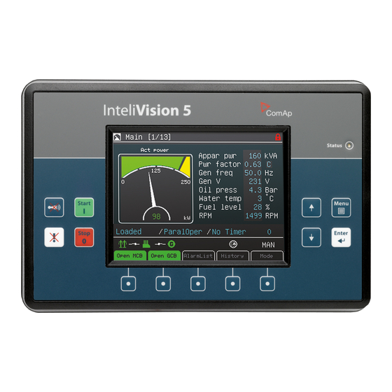
OFF MAN AUT TEST Ready Mains Oper 0.00 Timer 1. Operation mode of the gen-set 2. Indication of active alarm 3. Status of the gen-set InteliVision 5, InteliVision 8 – Operator guide, ©ComAp – January 2014 IGS-NT Operator Guide 01-2014.pdf... - Page 45 Bus V12, V23, V31 ph-ph (triple Mains V12, V23, V31 ph-ph (triple bargraph) bargraph) Bus (current) Mains (current, power, PF) Im3/EarthFC (single bargraph) Im3/EarthFC (single bargraph) InteliVision 5, InteliVision 8 – Operator guide, ©ComAp – January 2014 IGS-NT Operator Guide 01-2014.pdf...
- Page 46 Service time 4 Statistic Statistic kWhours kWhours kVArhours kVArhours Time Time Date Date Power management Engine priority Total running actual power Actual reserve (single barograph) CAN16 CAN32 InteliVision 5, InteliVision 8 – Operator guide, ©ComAp – January 2014 IGS-NT Operator Guide 01-2014.pdf...
-
Page 47: Description Of Intelisys Nt Measurement Screens
Opened Password is set. Password level is visible in lock opened lock. 10. Controller date and time. Can be set in Date/Time group of setpoints. InteliVision 5, InteliVision 8 – Operator guide, ©ComAp – January 2014 IGS-NT Operator Guide 01-2014.pdf... - Page 48 4. Required PF value 5. Actual Mains active power and PF values 6. Actual load active power and PF values 7. Actual gen-set active power and PF values InteliVision 5, InteliVision 8 – Operator guide, ©ComAp – January 2014 IGS-NT Operator Guide 01-2014.pdf...
- Page 49 1. Active power (total and per phase) 2. Power factor (total and per phase) 3. Reactive power (total and per phase) 4. Apparent power (total and per phase) InteliVision 5, InteliVision 8 – Operator guide, ©ComAp – January 2014 IGS-NT Operator Guide 01-2014.pdf...
- Page 50 5. Total gen-set kW hours 6. Total gen-set kVAr hours Note: Statistics can be set in InteliMonitor → Set statistics… after password of User 0 is entered. InteliVision 5, InteliVision 8 – Operator guide, ©ComAp – January 2014 IGS-NT Operator Guide 01-2014.pdf...
- Page 51 Primary water temperature) 3. Analog input 3 (e.g. Fuel level) 4. analog input 4 (e.g. Secondary water temperature) IS-NT binary inputs indication IS-NT binary outputs indication InteliVision 5, InteliVision 8 – Operator guide, ©ComAp – January 2014 IGS-NT Operator Guide 01-2014.pdf...
- Page 52 Further screens are automatically added if I/O extension modules or ECU are connected to the controller. History 1. Bottom lines show record number, reason, date and time even if other columns are actually displayed InteliVision 5, InteliVision 8 – Operator guide, ©ComAp – January 2014 IGS-NT Operator Guide 01-2014.pdf...
-
Page 53: Users And Passwords
Use ↑ or ↓ to select the desired password and then press ENTER. Use ← or → to move the value by 5% of the range. InteliVision 5, InteliVision 8 – Operator guide, ©ComAp – January 2014 IGS-NT Operator Guide 01-2014.pdf... -
Page 54: Mode And Function Description
Gen-set is controlled based on external signals (Rem start/stop, Sys start/stop) or conditions (AMF, Peak shaving, Power management system, …). Hint: Engine does not stop, if other condition for automatic starts is active. InteliVision 5, InteliVision 8 – Operator guide, ©ComAp – January 2014 IGS-NT Operator Guide 01-2014.pdf... -
Page 55: Test Mode (Sptm Only)
SEM mode. Baseload Process control: Load ctrl PtM = BASELOAD Gen-set power is kept at value given by Process control:Base load setpoint. InteliVision 5, InteliVision 8 – Operator guide, ©ComAp – January 2014 IGS-NT Operator Guide 01-2014.pdf... - Page 56 Controller measures Import/Export value via current transformers connected to In/Im3 terminal. The value of L3 is then multiplied by 3 to give an estimation of the actual Imp/Exp. InteliVision 5, InteliVision 8 – Operator guide, ©ComAp – January 2014 IGS-NT Operator Guide 01-2014.pdf...
-
Page 57: List Of Abbreviations
Communication Bridge - interfaces IS, IG/IS-NT, ID controllers and non- I-CB standard engine ECU IG-AVRi IG Automatic Voltage Regulator interface InteliGen for Electronic Engines (HW optimized for connection to an engine IG-EE equipped with ECU) InteliGen EE controller with extended communication possibilities + IG-EEC... - Page 58 Option for Low Temperature modification (display equipped with heating foil) Mains Circuit Breaker Master Generator Circuit Breaker (sometimes used with multiple gen-sets MGCB in island parallel or mains parallel operation) InteliVision 5, InteliVision 8 – Operator guide, ©ComAp – January 2014 IGS-NT Operator Guide 01-2014.pdf...
- Page 59 VAr Sharing - ensures VAr sharing between the gen-sets on the site via CAN bus (for isolated parallel or mains parallel of multiple gen-sets) InteliVision 5, InteliVision 8 – Operator guide, ©ComAp – January 2014 IGS-NT Operator Guide 01-2014.pdf...
Need help?
Do you have a question about the InteliGen and is the answer not in the manual?
Questions and answers