Table of Contents
Advertisement
Advertisement
Table of Contents

Related Manuals for HULTDINS SuperSaw 350E


Summary of Contents for HULTDINS SuperSaw 350E
- Page 1 SuperSaw 350E Installation manual...
- Page 2 This publication contains instructions for the installation and maintenance of the SuperSaw 350E grapple saw units. The instructions cover general information, procedures and specifications applicable to this grapple saw. If doubt should arise concerning the validity of the instructions please consult the nearest dealer for more detailed information.
-
Page 3: Table Of Contents
SuperSaw 350E - 19cc ........14 Maintenance instructions ........32 Special tools ............15 Regular maintenance .......... 32 Hydraulic diagram SuperSaw 350E / alt. 1..16 Daily maintenance ........32 Hydraulic diagram SuperSaw 350E / alt. 2..17 Lubrication ........... 33 Funktional description .......... - Page 4 CONTENTS (This page intentionally left empty for future additions) SuperSaw 350E Eng_ss350TOC.fm...
-
Page 5: Safety Instructions
S AF E T Y I NS T RUC T I ONS Safety instructions General safety • This page describes important safety instructions, which the operator should have a good knowledge of before the equipment is used. • This product should only be used by operators with proper knowledge and training. -
Page 6: Operational Safety
S AFE TY INS TRUCTIONS Operational Safety • Check the unit for damages at the beginning of each shift. • Make sure that the hydraulic pressure in the grapple cylinder is adjusted according to the specifications. If the pressure is too high, the unit will be overloaded, which could cause a structural failure, resulting in injury and/or property damage. -
Page 7: Maintenance Safety
It is not approved to: • Modify the grapple without the consent of HULTDIN SYSTEM AB. • Alter the function of the grapple without the consent of HULTDIN SYSTEM AB. • Use spare parts other than original HULTDINS parts. en011301_sc.fm Safety instructions... -
Page 8: Product Description
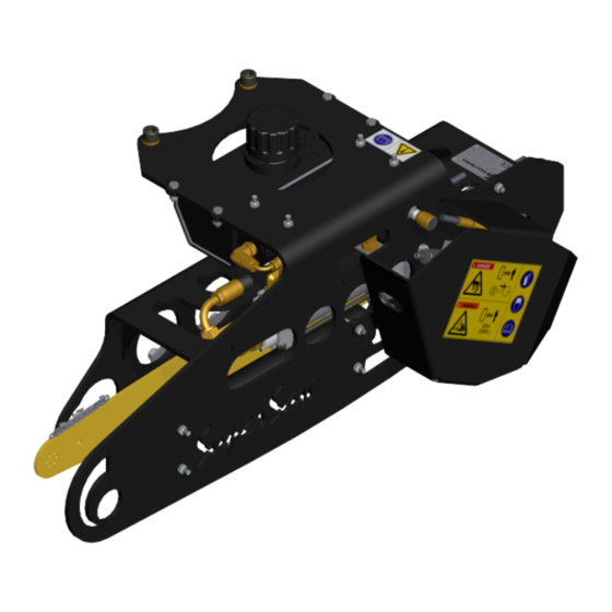
P RODUCT DESCRIPTION Product description Main parts, Grapple saw The SuperSaw 350E grapple saw consists basically of a frame, a saw unit and a hydraulic system. The illustration shows the location of the main parts. Fig. 1 Uppbyggnad SuperSaw 350E... -
Page 9: Adjustment Valves, Grapple Saw
PRODUCT DES CRIPTION product description Adjustment valves, Grapple saw The SuperSaw 350E grapple saw has the following adjustment valves. The location of the valves shows on the illustration. ill. 2 Adjustment valves 1 Pressure regulating valve for saw bar feed out pressure... -
Page 10: Hydraulic Pressure Test Points
P RODUCT DESCRIPTION product description Hydraulic pressure test points The SuperSaw 350E grapple saw has three different hydraulic pressure test points, as shown on the following illustration. ill. 3 Hydraulic pressure test points 1 Test point for saw bar feed out pressure... -
Page 11: Main Parts Supercut 100
PRODUCT DES CRIPTION Product description Main parts SuperCut 100 The SuperCut 100 saw unit is made up of the following main parts. ill. 4 Main parts SuperCut 100 1. Housing with integrated 4-point bearing/gear drive 2. Tension device 3. Bar holder 4. -
Page 12: Labeling
SuperGrip SG II is generally mounted on cranes intended for on road- and off road vehicles. SuperSaw 350E is only intended to be used for small timber, pulp- and waste wood systems. SuperSaw 350E must not be used for felling... -
Page 13: Technical Data
TECHNICAL DATA Technical Data SuperSaw 350E - 10cc Dimensions Total weight .404” 89 kg Length ‘A’ 1017 mm Width ‘B’ 446 mm Height ‘C’ 331 mm Width ‘D’ 99 mm Saw bar .404” 75 cm Hydraulic system Saw motor displacement 10 cm Min. -
Page 14: Supersaw 350E - 19Cc
TECHNICAL DATA Technical Data SuperSaw 350E - 19cc Dimensions Total weight .404” 94 kg Total weight 3/4” 96 kg Length ‘A’ 1017 mm Width ‘B’ 446 mm Height ‘C’ 331 mm Width ‘D’ 121 mm Saw bar .404” 67 / 75 cm Saw bar 3/4”... -
Page 15: Special Tools
Check valve key, P/N 0696011 Pressure gauge hose The pressure gauge hose, P/N 0724011, is used to connect a pressure gauge to the pressure test points on the saw motor manifold. See ill. 8. ill. 8 Pressure gauge hose, P/N 0724042 En010904c_ss350.fm SuperSaw 350E... -
Page 16: Hydraulic Diagram Supersaw 350E / Alt. 1
TECHNICAL DATA Technical data Hydraulic diagram SuperSaw 350E / alt. 1 ill. 9 Hydraulic diagram 1. Tension device 11. Rotator 2. Saw motor manifold 12. Accumulator for saw motor case drain 3. Air tank for saw bar retraction 13. Check valve 4. -
Page 17: Hydraulic Diagram Supersaw 350E / Alt. 2
TECHNICAL DATA Technical Data Hydraulic diagram SuperSaw 350E / alt. 2 ill. 10 Hydraulic diagram 1. Tension device 11. Rotator 2. Saw motor manifold 12. Accumulator for saw motor case drain 3. Air tank for saw bar retraction 13. Check valve 4. -
Page 18: Funktional Description
F UNKTIONAL DE SCRIP TION Funktional description SuperCut 100 The SuperCut 100 is made up of one Saw stand (1) which contains a 4-point bearing with a gear drive, a feed out cylinder (5) with integrated rack and proportional lubrication oil pump (6). -
Page 19: Chain Lubrication System
FUNCTIONAL DES CRIPTION Functional description swivel in the saw motor (6) and finally through the bar holder to the saw bar (8). The purpose of the pressure relief valve (9) is to limit the Chain lubrication system pressure in the lubrication circuit to prevent damages on the sviwel seals in the saw motor. -
Page 20: Installation
On the A-models of the SuperGrip II grapples, the SuperSaw 350 should be installed on the same side as the longer tips of the grapple arms, to optimize the performace of the grapple saw together with the grapple. SuperSaw 350E En011106a_ss350.FM... -
Page 21: Installation On Supergrip Ii
2. Use the drilling template and make four holes ø12,5- ø13mm on the side plate of the grapple. ill. 3 Drill four holes using the drilling template 3. Install the grapple saw to the grapple. ill. 4 Install the grapple saw to the grapple En011106a_ss350.FM SuperSaw 350E... -
Page 22: Hydraulic Installation
2. Connect the saw motor return line to port “2” on the rotator. 3. Connect the saw motor drain line to the pressure line “2” with a T-fitting. “1” Return line Drain line Pressure line ill. 5 Hydraulic installation SuperSaw 350E En011106a_ss350.FM... -
Page 23: Initial Upstart
Saw motor upstart Important! Fill the saw motor casing with hydraulic oil before starting the motor. Important! The warranty will not be valid if the motor is disassembled. ill. 6 Fill the casing with hydraulic oil before upstart En011306c_ss350.FM SuperSaw 350E... -
Page 24: Adjusting Saw Bar Feed Out Pressure
Increase the pressure by tightening the set screw. • Decrease the pressure by loosening the set screw. For a proper pressure range, refer to Technical Data. 6. Remove the pressure gauge and assemble the saw motor cover. SuperSaw 350E En011306c_ss350.FM... -
Page 25: Adjusting Saw Bar Feed Out
• If the pressure is decreased, the retraction speed will be lower. For a proper pressure range, refer to Technical Data ill. 9 Adjusting saw bar retraction 1 Air-tank 2 Adjustment nippel for air-pressure En011306c_ss350.FM SuperSaw 350E... -
Page 26: Adjusting Chain Tension Pressure
6. Repeat this process after 30-60 minutes of operation. 2 Check valve tool, P/N 0696011 3 Bar holder Important! Always bleed the system if there is any suspicion of air having entered the system, e.g. after replacing a hose or other component. SuperSaw 350E En011306c_ss350.FM... -
Page 27: Procedures
PROCEDURES Procedures Replacing saw chain The first signs of a worn chain are abnormally long saw times and blue smoke emerging from the cut. When replacing the saw chain we recommend the following method. Warning! Before performing any maintenance or service work, lower the attachment to the ground and shut off the engine. -
Page 28: Replacing Saw Bar
P ROCEDURE S Procedures Replacing saw bar Warning! Before performing any maintenance or service work, lower the attachment to the ground and shut off the engine. Turn off any master shut-offs and do not allow personnel in the cab. Important! When working on the saw chain always ensure the engine is shut off and wear safety gloves to prevent injuries. -
Page 29: Replacing Bar Holder
PROCEDURES Procedures Replacing bar holder When replacing the bar holder, always use the following method. 1. Place the unit steady on the ground with the saw unit facing up (when possible). 2. Remove the saw chain. See Replacing saw chain. 3. -
Page 30: Replacing Drive Sprocket
P ROCEDURE S Procedures Replacing drive sprocket Warning! A worn or damaged drive sprocket may cause damage or breakage to the saw chain. Warning! Before performing any maintenance or service work, lower the attachment to the ground and shut off the engine. -
Page 31: Refilling Chain Lubrication Oil
PROCEDURES Procedures Refilling chain lubrication oil Warning! Before performing any maintenance or service work, lower the attachment to the ground and shut off the engine. Turn off any master shut-offs and do not allow personnel in the cab. Warning! The attachment has sharp edges. Use proper wrenches and protective gloves when working on the attachment. -
Page 32: Maintenance Instructions
No damages or cracking have occurred on the unit. • There is no leakage on the unit. • At the beginning of each shift, always start with a sharp saw chain! Tighten any loose items and repair any damages. SuperSaw 350E En011307a_ss350.FM... -
Page 33: Lubrication
2. Bearing, 1 pcs. disassembled and cleaned at least every 1000 hours of operation or when necessary. The first month of operation Fasteners Tightening of the all fastners should be made once a week during the first month of operation. En011307a_ss350.FM SuperSaw 350E... - Page 34 Hultdin System AB 0113 - 7000249-EN Skolgatan 12, SE-930 70 MALÅ, Sweden Tel +46 953 418 00, Fax +46 953 418 01 E-mail: sales@hultdins.se...
Need help?
Do you have a question about the SuperSaw 350E and is the answer not in the manual?
Questions and answers