Lenovo RackSwitch G8296 Installation Manual
Hide thumbs
Also See for RackSwitch G8296:
- Quick start manual (22 pages) ,
- Installation manual (88 pages)
Table of Contents
Advertisement
Quick Links
Advertisement
Table of Contents

Related Manuals for Lenovo RackSwitch G8296


Summary of Contents for Lenovo RackSwitch G8296
-
Page 1: Installation Guide
Lenovo RackSwitch G8296 Installation Guide For Lenovo Network Operating System... - Page 2 LIMITED AND RESTRICTED RIGHTS NOTICE: If data or software is delivered pursuant a General Services Administration “GSA” contract, use, reproduction, or disclosure is subject to restrictions set forth in Contract No. GS-35F-05925. Lenovo and the Lenovo logo are trademarks of Lenovo in the United States, other countries, or both.
-
Page 3: Table Of Contents
Other Important Safety Notices ..... RackSwitch G8296 ..... . . 15 Port Configuration . - Page 4 Installing the G8296 in a Lenovo System x or Power Rack..43 Installing the G8296 in a Lenovo NeXtScale Rack ... 48 Installing the Air-Duct Option ..... 52 Installing Port Transceivers .
- Page 5 Power Specifications ......126 Switching Performance ......127 © Copyright Lenovo 2017 Contents...
- Page 6 Lenovo G8296 Installation Guide...
-
Page 7: Safety Information
Les sikkerhetsinformasjonen (Safety Information) før du installerer dette produktet. Przed zainstalowaniem tego produktu, należy zapoznać się z książką “Informacje dotyczace bezpieczeństwa” (Safety Information). Antes de instalar este produto, leia as Informações sobre Segurança. Перед установкой продукта прочтитe инcтрyкции по тexникe безопасности. © Copyright Lenovo 2017 Safety Information... - Page 8 Pred inštaláciou tohto zariadenia si prečítajte Bezpečnostné predpisy. Pred namestitvijo tega proizvoda preberite Varnostne informacije. Antes de instalar este producto, lea la información de seguridad. Läs säkerhetsinformationen innan du installerar den här produkten. Bu ürünü kurmadan önce güvenlik bilgilerini okuyun. Youq mwngz yungh canjbinj neix gaxgonq, itdingh aeu doeg aen canjbinj soengq cungj vahgangj ancien suisik.
-
Page 9: Safety Statements
Laser radiation when open. Do not stare into the beam, do not view directly with optical instruments, and avoid direct exposure to the beam. Class 1 Laser Product Laser Klasse 1 Laser Klass 1 Luokan 1 Laserlaite Appareil À Laser de Classe 1 © Copyright Lenovo 2017 Safety Information... - Page 10 Statement 5 CAUTION: The power control button on the device and the power switch on the power supply do not turn off the electrical current supplied to the device. The device also might have more than one power cord. To remove all electrical current from the device, ensure that all power cords are disconnected from the power source.
- Page 11 Connect and disconnect cables as described in the following table when you install, move, or open covers on this product or attached devices. © Copyright Lenovo 2017 Safety Information...
- Page 12 Multiple devices extended into the service position can cause your rack cabinet to tip. If you are not using the Lenovo 9308 rack cabinet, securely anchor the rack cabinet to ensure its stability. G8296 Installation Guide...
-
Page 13: Other Important Safety Notices
This product is also designed for IT power distribution systems with phase-to-phase voltage of 230V. This product is not intended for use in the direct field of view at visual display workplaces. Machinenlärminformations-Verordnung—3. GPSGV, der höchste Shalldruckpegel beträgt 70 dB (A) oder weniger. © Copyright Lenovo 2017 Safety Information... - Page 14 G8296 Installation Guide...
-
Page 15: Rackswitch G8296
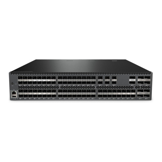
Chapter 1. RackSwitch G8296 This Installation Guide provides information about the Lenovo RackSwitch G8296 (referred to as G8296 throughout this document). The G8296 is a 2U rack-mountable aggregation switch used for combining traffic from multiple high-speed server racks. The G8296 uses a wire-speed, non-blocking switching fabric that provides simultaneous wire-speed transport of multiple packets at low latency on all ports. -
Page 16: G8296 Documentation
The console output described or referenced in this document might differ slightly from that displayed by your system. Output varies according to the type of Lenovo chassis and the firmware versions and options that are installed. Notices and Statements in this Document The Caution and Danger statements in this document are also in the multilingual Safety Information document, which is on the included Documentation CD. -
Page 17: The Documentation Cd
When the CD is mounted, open the directories and documents that support your product. Related Documentation Additional or updated product documents may be available from the Lenovo website. Such documents may cover features not described in the original documentation that comes with the switch, or may include technical updates or corrections. - Page 18 G8296 Installation Guide...
-
Page 19: Switch Components
Chapter 2. Switch Components This chapter describes the G8296 hardware components. © Copyright Lenovo 2017... -
Page 20: Switch Unit
QSFP+ Ports 94 96 93 95 90 92 89 91 SFP+ Ports Management Panel QSFP+ Ports Figure 2. RackSwitch G8296 management panel detail Reset Button Mini-USB Serial Console Port RJ-45 Management Port USB Port Status LEDs Figure 3. RackSwitch G8296 rear panel... -
Page 21: Management Panel
Console cable RJ-45 port connector pin assignments Pin Number Function RTS (Request To Send) DTR (Data Terminal Ready) TxD (Transmit Data) GND (Ground) GND (Ground) RxD (Receive Data) DSR (Data Set Ready) CTS (Clear To Send) © Copyright Lenovo 2017 Chapter 2: Switch Components... -
Page 22: Rj-45 Management Port
RJ-45 Management Port The RJ-45 management port on the front panel supports 10/100/1000BASE-T, in-line switch management. To attach an RJ-45 connector to the switch, push the RJ-45 cable connector into the port connector until it clicks into place. To disconnect the RJ-45 cable, squeeze the release tab and gently pull the cable connector out of the switch connector. -
Page 23: Reset Button
This action will also generate and save a log file. if the switch operates using Lenovo Cloud Network Operating System (CNOS): Normal reset—press and release reset button. The switch will start a forced ... -
Page 24: System Status Leds
USB drive, or from the USB drive to the switch. You can also start the switch using files on the USB drive. For more information about using the USB drive, see the Lenovo RackSwitch G8296 Release Notes. -
Page 25: Switching Ports
Some laser products contain an embedded Class 3A or Class 3B laser diode. Note the following. Laser radiation when open. Do not stare into the beam, do not view directly with optical instruments, and avoid direct exposure to the beam. © Copyright Lenovo 2017 Chapter 2: Switch Components... -
Page 26: Sfp+ Leds
QSFP+ optical transceiver with MTP-to-4 LC (SFP+) fiber breakout cable. This option supports only Lenovo 10GBASE-SR SFP+ transceivers. The 40GBASE-SR4 specification (802.3ba-2010) indicates a higher optical power level than standard 10GBASE-SR. Lenovo SFP+ SR transceivers can handle the higher optical power levels. This cable must be purchased separately. ... -
Page 27: Qsfp+ Leds
Status LEDs for the QSFP+ ports are described in the following table. Table 6. QSFP+ port status LED behavior State Functional Meaning Link Steady green Link up No link Flashing green Activity © Copyright Lenovo 2017 Chapter 2: Switch Components... -
Page 28: Rear Panel
Compatible fan options are listed in the Lenovo Networking Catalog. Fan operation and internal temperatures are monitored. If the air temperature exceeds a desired threshold, the environmental monitor displays warnings. - Page 29 Connect and disconnect cables as described in the following table when you install, move, or open covers on this product or attached devices. © Copyright Lenovo 2017 Chapter 2: Switch Components...
- Page 30 To Connect: To Disconnect: 1.Turn OFF all power sources and 1.Turn OFF all power sources and equipment that is to be attached to equipment that is to be attached to this product. this product. For ac systems, remove all power ...
-
Page 31: Power Leds
Power supply is operational. Green DC output power is present. DC output power is OK. Green AC power is OK. No power. Output is disabled, or input power is outside operating range. © Copyright Lenovo 2017 Chapter 2: Switch Components... - Page 32 G8296 Installation Guide...
-
Page 33: Installing G8296 Hardware And Options
Installing the switch in one of the supported rack types “Installing the G8296 in a Standard Equipment Rack” on page 40 “Installing the G8296 in a Lenovo System x or Power Rack” on page 43 “Installing the G8296 in a Lenovo NeXtScale Rack” on page 48 ... -
Page 34: Before Installing The G8296
Print this page and record product information below. Keep the information in a safe place for future reference. You will need this information when you register the switch or open a service call with Lenovo. Table 9. Important product information... -
Page 35: Required Tools
#2 Phillips screwdriver Electrostatic discharge wrist strap Package Contents The basic G8296 package contains the following items: One RackSwitch G8296 unit with front-to-rear or rear-to-front airflow One two-post mounting kit for standard 19” equipment racks: Two mounting brackets ... -
Page 36: Environmental Requirements
Environmental Requirements This section describes the basic environmental requirements for the G8296. Make sure the location where you install the switch meets the following requirements: Install the switch unit in a dry, clean, well-ventilated area. Provide adequate space in the front and back of the switch unit, to ensure proper ... -
Page 37: Preventing Electric Shock
Power cords for this product for a specific country or region are usually available only in that country or region. Power cord installation should also conform to the recommendations listed in “Cabling Guidelines” on page © Copyright Lenovo 2017 Chapter 3: Installing G8296 Hardware and Options... - Page 38 Statement 31 DANGER Electrical current from power, telephone, and communication cables is hazardous. To avoid a shock hazard: Do not connect or disconnect any cables or perform installation, maintenance, or reconfiguration of this product during an electrical storm. Connect all power cords to a properly wired and grounded power source.
-
Page 39: Handling Static-Sensitive Devices
Make sure that the radius of any bend does not exceed the vendor recommended minimum bend radius. Do not stress cables and connectors by applying additional twists, tension beyond load ratings, stapling, or applying nylon tie-wraps with a tie-wrap puller. © Copyright Lenovo 2017 Chapter 3: Installing G8296 Hardware and Options... -
Page 40: Installing The G8296 In A Rack
For a standard 19-inch equipment rack, use the 2-post rack mounting brackets and screws included with the switch. Installation instructions begin on page For a Lenovo System x or Power 4-post rack, use the Lenovo Adjustable 19” 4-Post Rail Kit. This kit must be purchased separately. Installation instructions... - Page 41 2. Attach a mounting bracket (Item 1) to each side of the switch with M4 screws (Item 2). Torque the screws to approximately 2.0 newton-meters (Nm) ± 0.1 Nm (17.7 inch-pounds). © Copyright Lenovo 2017 Chapter 3: Installing G8296 Hardware and Options...
- Page 42 3. From the front, slide the switch into the rack at the desired height. 4. Secure the switch unit to the rack posts with M6 screws (Item 3) and either clip nuts (Item 4) or cage nuts (Item 5). Torque the screws to approximately 5.7 Nm ± 0.1 Nm (50 inch-pounds).
-
Page 43: Installing The G8296 In A Lenovo System X Or Power Rack
Installing the G8296 in a Lenovo System x or Power Rack This section describes how to install the G8296 in a Lenovo System x or Power 4-post rack, using the Lenovo Adjustable 19” 4-Post Rail Kit. This kit must be purchased separately. It includes the following parts: Table 11. - Page 44 To install the G8296 in a System x or Power rack, complete the following steps: 1. Locate, record, and retain the product switch information in order to configure and register your product. See “Before Installing the G8296” on page Note: If this switch is a replacement switch, copy the product information from the original switch onto the RID label that is shipped with replacement switch and affix the new label to the bottom of the new switch.
- Page 45 (Item 4) or cage nuts (Item 5). Torque the screws to approximately 5.7 Nm ± 0.1 Nm (50 inch-pounds). 5. Place clip nuts (Item 4) or cage nuts (Item 5) on the rear posts. © Copyright Lenovo 2017 Chapter 3: Installing G8296 Hardware and Options...
- Page 46 6. Slide the rear mounting brackets (Item 7) into the slots available on the front mounting brackets. 7. If installing the 2U air-duct option, skip the two remaining steps in this section and see instead the instructions on “Installing the Air-Duct Option” on page 8.
- Page 47 11. Initialize the switch. See Chapter 5, “Initializing the G8296“. 12. If the switch is a replacement unit, set Vital Product Data (see “Configuring Vital Product Data” on page 83). © Copyright Lenovo 2017 Chapter 3: Installing G8296 Hardware and Options...
-
Page 48: Installing The G8296 In A Lenovo Nextscale Rack
Installing the G8296 in a Lenovo NeXtScale Rack This section describes how to install the G8296 in a Lenovo NeXtScale 4-post rack, using the Lenovo Adjustable 19” 4-Post Rail Kit. The kit must be purchased separately. It includes the following parts: Table 12. - Page 49 M4 screws (Item 2). Torque the screws to approximately 2.0 newton-meters (Nm) ± 0.1 Nm (17.7 inch-pounds). 3. From the front, slide the switch into the rack at the desired height. © Copyright Lenovo 2017 Chapter 3: Installing G8296 Hardware and Options...
- Page 50 4. Secure the front mounting brackets to the front rack posts with M6 screws (Item 3) and either clip nuts (Item 4) or cage nuts (Item 5). Torque the screws to approximately 5.7 Nm ± 0.1 Nm (50 inch-pounds). 5. Slide the rear mounting brackets (Item 7) into the slots available on the front mounting brackets, then secure them to the rear rack posts with M6 screws (Item 3) and either clip nuts (Item 4) or cage nuts (Item 5).
- Page 51 9. Initialize the switch. See Chapter 5, “Initializing the G8296“. 10. If the switch is a replacement unit, set Vital Product Data (see “Configuring Vital Product Data” on page 83). © Copyright Lenovo 2017 Chapter 3: Installing G8296 Hardware and Options...
-
Page 52: Installing The Air-Duct Option
Installing the Air-Duct Option The G8296 supports an optional 2U air duct to maximize air flow conditions in a Lenovo System x or Power 4-post rack. It is not compatible with 2-post racks or with the Lenovo NeXtScale rack. For information on removing an installed 2U air-duct option, see “Removing the... - Page 53 To install the 2U air-duct option, complete the following steps: 1. Install the switch in a 4-post rack as described in “Installing the G8296 in a Lenovo System x or Power Rack” on page Note: If installing the 2U air-duct option to a previously mounted switch, first remove and retain the rear-bracket mounting screws and joining screws on both sides.
- Page 54 3. Attach the switch and air-duct mounting brackets to the rear rack posts using M6 screws from the 4-post rail kit. Torque the screws to approximately 5.7 Nm ± 0.1 Nm (50 inch-pounds). 4. Attach a foam baffle (Item 5) to the mounting brackets at each side of the switch with M3.5 screws (Item 6).
- Page 55 5. Use the cable ties (Item 1) to secure the switch AC power cords to the air-duct mounting brackets. 6. Insert the air-duct sleeve into the rear of the rack, matching the air-duct guides to the rails in the air-duct mounting brackets on both sides. © Copyright Lenovo 2017 Chapter 3: Installing G8296 Hardware and Options...
- Page 56 7. Secure the air-duct sleeve to the rack with the four M4 thumbscrews. G8296 Installation Guide...
-
Page 57: Installing Port Transceivers
“Cabling Guidelines” on page To remove an SFP copper transceiver, disconnect the cable, and pull down the locking lever to release the transceiver. After you remove the transceiver, replace the safety cap. © Copyright Lenovo 2017 Chapter 3: Installing G8296 Hardware and Options... -
Page 58: Installing An Sfp Optical Transceiver
Installing an SFP Optical Transceiver Approved 1 GbE SFP optical transceivers are supported in G8296 SFP+ port slots and in some breakout adapters that can be installed in QSFP+ port slots. The SFP optical transceiver provides two fiber-optic cable connectors for connecting to external ports. - Page 59 To remove an SFP optical transceiver, disconnect the fiber-optic cable, and pull down the locking lever to release the transceiver. After you remove the transceiver, replace the safety cap. © Copyright Lenovo 2017 Chapter 3: Installing G8296 Hardware and Options...
-
Page 60: Installing An Sfp+ Optical Transceiver
Installing an SFP+ Optical Transceiver Approved 10 GbE SFP+ optical transceivers are supported in G8296 SFP+ port slots and in some breakout adapters that can be installed in QSFP+ port slots. The SFP+ optical transceiver provides two fiber-optic cable connectors for connecting to external ports. - Page 61 To remove an SFP+ optical transceiver, disconnect the fiber-optic cable, and pull down the locking lever to release the transceiver. After you remove the transceiver, replace the safety cap. © Copyright Lenovo 2017 Chapter 3: Installing G8296 Hardware and Options...
-
Page 62: Installing A Qsfp+ Optical Transceiver
Installing a QSFP+ Optical Transceiver The QSFP+ ports accept approved QSFP+ transceivers. The QSFP+ optical transceiver provides an MTP cable connector for connecting to external ports. Statement 3 CAUTION: When laser products (such as CD-ROMs, DVD drives, fiber optic devices, or transmitters) are installed, note the following: ... -
Page 63: Remove The Safety Cap And Pull The Locking Lever Into The Down (Unlocked) Position
To remove a QSFP+ optical transceiver, disconnect the fiber-optic cable, and pull down the locking lever to release the transceiver. After you remove the transceiver, replace the safety cap. © Copyright Lenovo 2017 Chapter 3: Installing G8296 Hardware and Options... - Page 64 G8296 Installation Guide...
-
Page 65: Removing And Replacing Components
“Removing the G8296 from a Standard Equipment Rack” on page 74 “Removing the switch from a Lenovo System x or Power Rack” on page 76 “Removing the G8296 from a Lenovo NeXtScale Rack” on page 79 ... -
Page 66: Removing Port Transceivers
Removing Port Transceivers Statement 3 CAUTION: When laser products (such as CD-ROMs, DVD drives, fiber optic devices, or transmitters) are installed, note the following: Do not remove the covers. Removing the covers of the laser product could result in exposure to hazardous laser radiation. There are no serviceable parts inside the device. -
Page 67: Removing And Replacing A Power Supply Module
The device also might have more than one power cord. To remove all electrical current from the device, ensure that all power cords are disconnected from the power source. © Copyright Lenovo 2017 Chapter 4: Removing and Replacing Components... - Page 68 To remove a hot-swap power supply module, complete the following steps: 1. Remove the power cord from the module’s power connector. 2. Press the release latch of the power supply module, and slide the module out of the bay. Release Latch Attention: Do not leave the power-supply bay empty for more than 90 seconds while the switch is operating.
-
Page 69: Replacing The Power Supply Module
Connect and disconnect cables as described in the following table when you install, move, or open covers on this product or attached devices. © Copyright Lenovo 2017 Chapter 4: Removing and Replacing Components... - Page 70 To Connect: To Disconnect: 1.Turn OFF all power sources and 1.Turn OFF all power sources and equipment that is to be attached to equipment that is to be attached to this product. this product. For ac systems, remove all power ...
- Page 71 3. Connect the power cord to the power supply module and to an appropriate universal grounded AC power source. 4. Make sure that the power supply module’s DC and AC LEDs are green. © Copyright Lenovo 2017 Chapter 4: Removing and Replacing Components...
-
Page 72: Removing And Replacing A Fan Module
Removing and Replacing a Fan Module The rear panel of the G8296 has three bays for hot-swap fan modules. Three active fan modules are required for redundancy. With active fan modules in all fan bays, if one fan fails, the switch will send an error message and continue operation. -
Page 73: Replacing The Fan Module
(see the illustration). Each fan module has a mechanical guide key to prevent you from inserting the module incorrectly. Engage Latch 4. Make sure that the fan module’s LED is lit. © Copyright Lenovo 2017 Chapter 4: Removing and Replacing Components... -
Page 74: Removing The G8296 From A Standard Equipment Rack
Removing the G8296 from a Standard Equipment Rack This section describes how to remove the G8296 from a standard 19-inch equipment rack. For information about removing the switch from other supported racks, see the appropriate section in this chapter. To remove the G8296 from a standard rack, complete the following steps: 1. - Page 75 4. Loosen and remove the M4 screws attaching the mounting bracket on each side of the switch. 5. If replacing the unit with another G8296, see “Replacing the G8296” on page © Copyright Lenovo 2017 Chapter 4: Removing and Replacing Components...
-
Page 76: Removing The Switch From A Lenovo System X Or Power Rack
Removing the switch from a Lenovo System x or Power Rack This section describes how to remove the G8296 from a Lenovo System x or Power 4-post rack. To remove the G8296 from a System x or Power rack, complete the following steps: 1. - Page 77 5. At the front of the rack, loosen and remove the M6 screws, washers, and clip nuts are used to connect the front mounting brackets to the front posts in the rack. © Copyright Lenovo 2017 Chapter 4: Removing and Replacing Components...
- Page 78 6. Slide the G8296 unit out of the rack. 7. Loosen and remove the M4 screws that attach the front mounting brackets to each side of the switch. 8. If replacing the unit with another G8296, see “Replacing the G8296” on page G8296 Installation Guide...
-
Page 79: Removing The G8296 From A Lenovo Nextscale Rack
Removing the G8296 from a Lenovo NeXtScale Rack This section describes how to remove the G8296 from a Lenovo NeXtScale 4-post rack. To remove the G8296 from a NeXtScale rack, complete the following steps: 1. Disconnect all external cables. 2. Loosen and remove the rear-most set of M4 screws securing the mounting brackets to the side of the switch. - Page 80 3. Loosen and remove the M6 screws and clip nuts (or cage nuts) securing the rear mounting brackets to the rear rack posts, then slide the rear brackets out of their slots in the front mounting brackets. 4. At the front of the rack, loosen and remove the M6 screws, washers, and clip nuts are used to connect the front mounting brackets to the front posts in the rack.
- Page 81 6. Loosen and remove the M4 screws that attach the front mounting brackets to each side of the switch. 7. If replacing the unit with another G8296, see “Replacing the G8296” on page © Copyright Lenovo 2017 Chapter 4: Removing and Replacing Components...
-
Page 82: Removing The Air-Duct Option
Removing the Air-Duct Option The G8296 supports an optional 2U air duct to maximize air flow conditions in a Lenovo Power Systems Group rack. To remove an installed 2U air-duct option from a 19” rack, complete the following steps. 1. Loosen the M4 thumbscrews securing the air-duct unit to the mounting brackets. -
Page 83: Replacing The G8296
G8296“. At the login prompt, the default username is admin and the default password is admin. 2. Use the following CLI commands to enter the Executive configuration mode: for Lenovo Enterprise Network Operating System (ENOS): G8296> enable G8296# configure terminal G8296(config)# ... - Page 84 3. Set the new switch to use the Machine Type-Model (MTM) number of the old unit. For example: for Lenovo Enterprise Network Operating System (ENOS): G8296(config)# boot mtm 1234-56X New MTM value: 1234-56X Please reset the system for the new changes to take effect ...
- Page 85 System Serial Number: XX01234567 For more information about using the switch interface, see the Application Guide and Command Reference for the G8296 and its corresponding Lenovo Network Operating System and firmware version. © Copyright Lenovo 2017 Chapter 4: Removing and Replacing Components...
- Page 86 G8296 Installation Guide...
-
Page 87: Initializing The G8296
The device also might have more than one power cord. To remove all electrical current from the device, ensure that all power cords are disconnected from the power source. © Copyright Lenovo 2017... -
Page 88: System Status Leds
System Status LEDs The following LEDs on the switch front panel indicate the overall system status: Power: Steady green if the both power cords are connected, or flashing green if the only one power cord is connected. Service ( ! ): Off if the system is OK, or flashing if service is required. ... -
Page 89: Connecting To The Switch
CLI through the RJ-45 management port. This port uses Ethernet communications and can be accessed using Telnet, SNMP, or a Web browser via the IP address provided by the network’s DHCP server. © Copyright Lenovo 2017 Chapter 5: Initializing the G8296... -
Page 90: Logging Into The Switch
Logging Into the Switch When the switch starts, it performs initial self tests, and then prompts for the password. For example: U-Boot 2014.01 (Jan 26 2017 - 07:10:58) - lenovo CPU0: P2020, Version: 2.1, (0x80e20021) Core: e500, Version: 5.1, (0x80211051) -
Page 91: Default Configuration Files
However, if desired, you can revert the custom configuration settings to the original factory defaults. The original factory default configuration files are a permanent part of the firmware; you cannot deleted them or change their original definitions. © Copyright Lenovo 2017 Chapter 5: Initializing the G8296... -
Page 92: Configuring The Management Interface For Remote Access
1. Log onto the switch using the serial console port or management port on the G8296 front panel. 2. Enter management interface mode. for Lenovo Enterprise Network Operating System (ENOS): G8296> enable G8296# configure terminal G8296(config)# interface ip 128... - Page 93 for Lenovo Cloud Network Operating System (CNOS): G8296(config-if)# ip address 10.254.87.6 G8296(config-if)# ip netmask 255.255.255.0 G8296(config-if)# vlan 1 G8296(config-if)# exit G8296(config)# 4. Configure the default gateway. for Lenovo Enterprise Network Operating System (ENOS): G8296(config)# ip gateway 4 address 205.21.17.1 G8296(config)# ip gateway 4 enable ...
-
Page 94: Updating Firmware
Updating Firmware If firmware updates are available, you can download them from the Lenovo website. The switch might have features that are not described in the documentation that comes with the switch, and the documentation might be updated occasionally to include information about those features, or technical updates might be available to provide additional information that is not included in the switch documentation. -
Page 95: The Boot Management Menu
To reset the default user password, press <P> and follow the screen prompts. To reload the switch, press <Q>. The reloading process will start again. To exit the Boot Management menu, press <E>. The reloading process continues. © Copyright Lenovo 2017 Chapter 5: Initializing the G8296... -
Page 96: Boot Recovery Mode
Boot Recovery Mode The Boot Recovery Mode allows you to recover from a failed software or boot image upgrade using TFTP or XModem download. To enter Boot Recovery Mode you must select the Startup in recovery mode option from the Boot Management Menu. Entering Rescue Mode. -
Page 97: Recover From A Failed Image Upgrade Using Tftp
9. Enter the IP address of the TFTP server: Server addr: 10. Enter the file path and the filename of the image: Image Filename: After the procedure is complete, the Recovery Mode menu will be redisplayed. © Copyright Lenovo 2017 Chapter 5: Initializing the G8296... - Page 98 Following is an example of a successful recovery procedure using TFTP: Entering Rescue Mode. Please select one of the following options: T) Configure networking and tftp download an image X) Use xmodem 1K to serial download an image P) Physical presence (low security mode) F) Filesystem check R) Reboot E) Exit...
-
Page 99: Recovering From A Failed Image Upgrade Using Xmodem Download
Serial Port speed back to 9600 bps: Change the baud rate back to 9600 bps, hit the <ENTER> key 9. Press <Enter> to start installing the image. © Copyright Lenovo 2017 Chapter 5: Initializing the G8296... - Page 100 The image install will begin. After the procedure is complete, the Recovery Mode menu will be redisplayed. Extracting images ... Do *NOT* power cycle the switch. Installing Root Filesystem: Image signature verified. 100% Installing Kernel: Image signature verified. 100% Installing Device Tree: Image signature verified.
-
Page 101: Physical Presence
After the test is completed, the switch will be put in low security mode. This mode will allow you to install special images on the switch. To revert to normal security mode, you must reboot the switch or press <P> again in the Recovery Mode menu. © Copyright Lenovo 2017 Chapter 5: Initializing the G8296... - Page 102 G8296 Installation Guide...
-
Page 103: Troubleshooting
If you have problems accessing the switch or working with the firmware, see the G8296 Application Guide and/or the Command Reference. For information about calling Lenovo for service, see Appendix A, “Getting Help and Technical Assistance“. -
Page 104: System Led Is Not Lit
System LED Is Not Lit Symptom: The power supply LED is not lit. Solution: Check the power supply to make sure that there is a proper connection to the power source. Make sure that power is available from the power source. G8296 Installation Guide... -
Page 105: Port Link Led Is Not Lit
Solution 2: Check the cables that connect the port to the other device. Make sure that they are connected correctly. Make sure that you are using the correct cable type. © Copyright Lenovo 2017 Chapter 6: Troubleshooting... -
Page 106: Temperature Sensor Warning
Make sure that all cooling fans inside the switch are running. A fan module LED (rear panel) flashes if there is a failure of the fan. The following CLI command displays fan status: for Lenovo Enterprise Network Operating System (ENOS): G8296> show sys-info ... -
Page 107: Switch Does Not Initialize (Boot)
Symptom: All the switch LEDs stay on, and the command prompt is not displayed on the console. Solution: The operating system might be damaged. Use the console port to perform a serial upgrade of the switch firmware. See the Command Reference. © Copyright Lenovo 2017 Chapter 6: Troubleshooting... - Page 108 G8296 Installation Guide...
-
Page 109: Getting Help And Technical Assistance
Lenovo to assist you. Use this information to obtain additional information about Lenovo and Lenovo products, and determine what to do if you experience a problem with your Lenovo system or optional device. Note: This section includes references to IBM web sites and information about obtaining service. - Page 110 Electronic Service Request. You can solve many problems without outside assistance by following the troubleshooting procedures that Lenovo provides in the online help or in the Lenovo product documentation. The Lenovo product documentation also describes the diagnostic tests that you can perform. The documentation for most systems, operating systems, and programs contains troubleshooting procedures and explanations of error messages and error codes.
-
Page 111: Notices
Web sites. The materials at those Web sites are not part of the materials for this Lenovo product, and use of those Web sites is at your own risk. - Page 112 Any performance data contained herein was determined in a controlled environment. Therefore, the result obtained in other operating environments may vary significantly. Some measurements may have been made on development-level systems and there is no guarantee that these measurements will be the same on generally available systems.
-
Page 113: Trademarks
Trademarks Lenovo, the Lenovo logo, Flex System, System x, NeXtScale System, and X-Architecture are trademarks of Lenovo in the United States, other countries, or both. Intel and Intel Xeon are trademarks of Intel Corporation in the United States, other countries, or both. -
Page 114: Important Notes
(TBW). A device that has exceeded this limit might fail to respond to system-generated commands or might be incapable of being written to. Lenovo is not responsible for replacement of a device that has exceeded its maximum guaranteed number of program/erase cycles, as documented in the Official Published Specifications for the device. -
Page 115: Recycling Information
Recycling Information Lenovo encourages owners of information technology (IT) equipment to responsibly recycle their equipment when it is no longer needed. Lenovo offers a variety of programs and services to assist equipment owners in recycling their IT products. For information on recycling Lenovo products, go to: http://www.lenovo.com/recycling... -
Page 116: Particulate Contamination
If Lenovo determines that the levels of particulates or gases in your environment have caused damage to the device, Lenovo may condition provision of repair or replacement of devices or parts on implementation of appropriate remedial measures to mitigate such environmental contamination. -
Page 117: Telecommunication Regulatory Statement
This product may not be certified in your country for connection by any means whatsoever to interfaces of public telecommunications networks. Further certification may be required by law prior to making any such connection. Contact a Lenovo representative or reseller for any questions. © Copyright Lenovo 2017 Appendix B: Notices... -
Page 118: Electronic Emission Notices
Properly shielded and grounded cables and connectors must be used to meet FCC emission limits. Lenovo is not responsible for any radio or television interference caused by using other than recommended cables and connectors or by unauthorized changes or modifications to this equipment. -
Page 119: European Union - Compliance To The Electromagnetic Compatibility Directive
Grenzwerte der Klasse A der Norm gemäß Richtlinie. Um dieses sicherzustellen, sind die Geräte wie in den Handbüchern beschrieben zu installieren und zu betreiben. Des Weiteren dürfen auch nur von der Lenovo empfohlene Kabel angeschlossen werden. Lenovo übernimmt keine Verantwortung für die Einhaltung der Schutzanforderungen, wenn das Produkt ohne Zustimmung der Lenovo verändert bzw. -
Page 120: Japan Vcci Class A Statement
Dieses Gerät ist berechtigt, in Übereinstimmung mit dem Deutschen EMVG das EG-Konformitätszeichen - CE - zu führen. Verantwortlich für die Konformitätserklärung nach Paragraf 5 des EMVG ist die Lenovo (Deutschland) GmbH, Meitnerstr. 9, D-70563 Stuttgart. Informationen in Hinsicht EMVG Paragraf 4 Abs. (1) 4: Das Gerät erfüllt die Schutzanforderungen nach EN 55024 und EN 55022 Klasse... -
Page 121: Japan Electronics And Information Technology Industries Association (Jeita) Statement
Sellers and users need to pay attention to it. This is for any areas other than home. Russia Electromagnetic Interference (EMI) Class A statement People’s Republic of China Class A electronic emission statement Taiwan Class A compliance statement © Copyright Lenovo 2017 Appendix B: Notices... - Page 122 G8296 Installation Guide...
-
Page 123: Technical Specifications
Appendix C. Technical Specifications The G8296 technical specifications are described in the following sections. © Copyright Lenovo 2017... -
Page 124: Physical Characteristics
Physical Characteristics The physical characteristics of the G8296 are listed in the following table. Table 14. Physical characteristics Specification Physical characteristics Dimensions (H x W x D) 4.45 x 43.9 x TBD cm (1.75 x 17.3 x TBD in) Weight 15.4 kg (34 lb) maximum Airflow Available options for rear to front,... -
Page 125: Environmental Specifications
Relative humidity (non-condensing), 10 to 90% storage Altitude, operating 1,800 m (6,000 ft) Altitude, storage 12,190 m (40,000 ft) Acoustic noise Less than 65dB Heat dissipation 717 BTU/h (typical) 1,433 BTU/h (maximum) © Copyright Lenovo 2017 Appendix C: Technical Specifications... -
Page 126: Power Specifications
Power Specifications The power specifications for the G8296 are listed in the following table. Table 16. G8296 AC power specifications Specification Measurement Number of power supplies 2 (1+1 load sharing/redundant) AC-input frequency (universal) 50–60 Hz AC-input voltage (universal) 100–240 VAC AC inrush current AC-input current (typical) 1.74 A (RMS) @ 120 VAC... -
Page 127: Switching Performance
Note: The specific features supported on your switch, as well as some capacity and performance characteristics, depend on the specific firmware installed. For more information, see the Application Guide and Command Reference for your specific switch and its installed firmware. © Copyright Lenovo 2017 Appendix C: Technical Specifications... - Page 128 G8296 Installation Guide...