YOKOGAWA YFGW410 User Manual
Field wireless management station
Hide thumbs
Also See for YFGW410:
- User manual (67 pages) ,
- Startup manual (45 pages) ,
- User manual (22 pages)

Related Manuals for YOKOGAWA YFGW410


Summary of Contents for YOKOGAWA YFGW410
- Page 1 User’s Manual YFGW410 Field Wireless Management Station IM 01W02D01-01EN IM 01W02D01-01EN 5th Edition...
-
Page 2: Table Of Contents
Information of User’s Manual Revision ...............iv Part A Outline of Field Wireless System Configuration Minimum System Configuration ............A1-1 Minimum System Configuration with Redundant Field Wireless Network ....................A2-1 YFGW410 in Redundant Configuration ..........A3-1 YFGW410 in High-Level Redundancy Configuration ......A4-1 IM 01W02D01-01EN... - Page 3 Security Manager ................... B2-1 B2.3 Gateway ......................B2-1 B2.4 Wireless Network Configuration and Management Functions and Others ......................B2-2 Structure and Parts of YFGW410 ............B3-1 B3.1 Front View ....................... B3-1 B3.2 Top View ......................B3-1 B3.3 Side and Rear Views ..................B3-2 B3.4...
- Page 4 Grounding ....................... C2-2 Mounting ....................C3-1 C3.1 Mounting Direction ..................C3-1 C3.2 Mounting to DIN Rails ..................C3-2 C3.3 Installation of the YFGW410 ................. C3-3 Wiring .......................C4-1 C4.1 Terminals and Communication Ports Connection ........C4-1 C4.2 Power Supply Cable Connection ..............C4-2 C4.3 Grounding .......................
- Page 5 Provisioning ....................D3-1 Constructing a Field Wireless System ..........D4-1 D4.1 Setting Operation Items ................D4-1 D4.2 Detail of Configuration ................. D4-2 D4.2.1 YFGW410 Settings ................ D4-2 D4.2.2 Operation Mode ................D4-15 D4.2.3 Hopping Patterns ................. D4-15 D4.2.4 Field Wireless Networks .............. D4-20 D4.2.5...
- Page 6 Handling a Device in the Warning Status .............E1-2 Adding and Replacing a Device ............E2-1 E2.1 Field Wireless Device ..................E2-1 E2.2 Field Wireless Access Point (YFGW510) ............E2-3 E2.3 Field Wireless Management Station (YFGW410).........E2-3 YFGW410 Maintenance in Hazardous Area .........E3-1 Parts with Defined Life Spans ...............E4-1 IM 01W02D01-01EN...
- Page 7 Toc-6 Part F Troubleshooting Field Wireless System ................F1-1 YFGW410 ....................F2-1 F2.1 Status Information ..................F2-1 F2.2 Status Indicators and Actions ...............F2-2 F2.3 Data Status Specification ................F2-4 IM 01W02D01-01EN...
- Page 8 Toc-7 Part G Specifications YFGW410 ....................G1-1 G1.1 Standard Specification .................. G1-1 G1.2 Model and Suffix Codes ................G1-3 G1.3 External Dimensions ..................G1-4 Field Wireless Network ................. G2-1 G2.1 Field Wireless Network Specification ............G2-1 G2.2 Network Form (Topology) ................G2-2 G2.2.1...
-
Page 9: Introduction
This document describes the YFGW410 Field Wireless Management Station (hereafter simply refered to as YFGW410), which is a core component of the field wireless system that based on ISA100.11a, the wireless communication standard for industrial automation specified by the International Society of Automation (ISA). Functions of the YFGW410 are explained in the outline of the field wireless system, and in the installation, configuration, startup and operations of the field wireless network. The operation of Field Wireless Management Console, which is built in to the YFGW410 and used as a tool for setup and management of a field wireless network through YFGW410, is also explained in this document. IM 01W02D01-01EN... -
Page 10: Safety Precautions
<Read Me First> Safety Precautions IMPORTANT Be sure to read the safety precautions for this product described in “YFGW410 Field Wireless Management Station Read Me First (IM 01W02D01-11EN)”. This instrument has been tested and certified as being explosion proof. Be sure to read the safety precautions and explosion proof specifications described in “YFGW410 Field Wireless Manage- ment Station Read Me First (IM 01W02D01-11EN)” before the installation and operation of this instrument. -
Page 11: Documentation Conventions
Characters enclosed in corner brackets show a tab or an item of the screen during the explana- tion of the software operation. Symbols used in the manual The symbol used in the manual are described in “YFGW410 Field Wireless Management Station Read Me First” (IM 01W02D01-11EN). Drawing Conventions Some drawings may be partially emphasized, simplified, or omitted, for the convenience of de- scription. -
Page 12: Information Of User's Manual Revision
<Read Me First> Information of User’s Manual Revision Material Name : YFGW410 Field Wireless Management Station Material Number : IM 01W02D01-01EN Edition Date Page Revised Item August 2012 New Issue Revise descriptions about a number of connectable devices, February 2013 and typography. - Page 13 <Read Me First> Edition Date Page Revised Item June 2017 A3-2, A4-2 Add note about firmware revision and license when redundant configuration B2-3 Modify description about Modbus functions D2-3, D2-6 to 7 Change System Requirements D3-2 Delete description of YFGW710 D4-3 to 9, 11, D4-80 Revise FWMC window image D4-68 Add description about the condition of sending the data written to Modbus holding register...
-
Page 14: Part A Outline Of Field Wireless System Configuration
A1-1 <A1. Minimum System Configuration> Part A Outline of Field Wireless System Configuration The YFGW410, the YFGW510 Field Wireless Access Point (hereafter simply refered to as YFGW510), the YFGW610 Field Wireless Media Converter (hereafter simply refered to as YFGW610) and field wireless devices are used to build an industrial wireless network that based on to ISA100.11a, the wireless communication standard for industrial automation specified by the International Society of Automation (ISA). - Page 15 • The wireless LAN network shown in Figure A1-3, composed of other manufactures’ wireless LAN access point (connected to the YFGW410) for wireless LAN communication with the YFGW510 (wireless LAN client model). The Field Wireless Management Console, which is the program built in to the YFGW410, is used for configuration and management of a field wireless network. This program can be started and operated by the PC connected via the field network interface or via the maintenance interface of the YFGW410.
- Page 16 Figure A1-2 Minimum system configuration example (The field wireless backbone using optical network) In this configuration, YFGW610 and YFGW510 are connected through optical network cables. The YFGW610 needs to be installed near YFGW410 for media conversion between optical network and metal network.This is a useful method if the distance is too far from YFGW410 to YFGW510. Also in order to eliminate the influence of electromagnetic noise due to lightning and keep transmission distance.
-
Page 17: Network
A1-4 <A1. Minimum System Configuration> Host system Field Wireless Management Station (YFGW410) Field Wireless Management Console Subnet A Subnet B Wireless LAN access point Wireless LAN access point (other manufactures) (other manufactures) Wireless LAN Wireless LAN Field Wireless Field Wireless Access Point Access Point... - Page 18 A2-1 <A2. Minimum system configuration with redundant field wireless network> A2. Minimum System Configuration with Redundant Field Wireless Network Host system Field Wireless Management Station (YFGW410) Field Wireless Management Console Subnet A Field Wireless Field Wireless Access Point Access Point (YFGW510) (YFGW510) Field wireless network (ISA100.11a) Field wireless device FA0201.ai...
-
Page 19: A3. Yfgw410 In Redundant Configuration
FA0301.ai Figure A3-1 Redundant system configuration of YFGW410 In this example, the both of YFGW410 and YFGW510 are made redundant system. In using the Duocast, the field wireless devices are made fully redundant and a highly reliable system. Two YFGW410 virtually operate as a single machine, and the backbone devices and host system devices access to this virtual machine. - Page 20 A3-2 <A3. YFGW410 in Redundant Configuration> IMPORTANT When CENTUM VP is used with YFGW410 in redundant configuration, CENTUM VP R5.02.00 or higher is required. For details, see the Communication with Subsystems Using FIO user’s manual (IM 33J20A30-01EN for R6, or IM 33K03L20-50E for R5). IMPORTANT YFGW410 in redundant configuration cannot be used with combinations of different firmware versions or specifications such as license and communication protocols. IM 01W02D01-01EN...
-
Page 21: A4. Yfgw410 In High-Level Redundancy Configuration
Figure A4-1 High-Level redundancy system configuration of YFGW410 In this configuration, the system consists of redundant YFGW410 and redundant Modbus/TCP client of the host system. Yokogawa’s Modbus/TCP client can be made redundant using the FCS (Field Control Station) of CENTUM VP. For details, see the CENTUM VP User’s Manual (IM 33J20A30-01EN for R6, or IM 33K03L20-50E for R5). - Page 22 A4-2 <A4. YFGW410 in High-Level Redundancy Configuration> In the redundant YFGW410, need to connect the system to the YFGW510 using following meth- • Direct connection between YFGW410 and YFGW510 (shown in Figure A3-1) • A single L2SW is installed for each backbone device. The L2SW have to connect as a loop.
-
Page 23: B1. Introduction
B1-1 <B1. Introduction> Part B YFGW410 Product Description B1. Introduction This chapter outlines the functions and hardware configuration of the YFGW410. YFGW410 is a core device in the field wireless network, and it is used for configuration and man- agement of a field wireless network and for data transfer to the host system. A single YFGW410 is always required for the field wireless network, and two YFGW410s are required for redundacy system. The YFGW410 can be mounted on the DIN rails, and it is usually mounted on the panel or wall in the cabinet. IM 01W02D01-01EN... -
Page 24: B2. Yfgw410 Function Outline
Also, the gateway relays a request and its response between the host system and field wireless devices. The Gateway can cache the diagnosis data acquired through communication with the field wire- less device in the YFGW410’s internal memory. The efficient communication to wireless field devices can use a wireless band flexibly and improve the response to the host system. IMPORTANT When access to the Modbus registers that are not mapped in YFGW410, a non-zero data may be contained. IM 01W02D01-01EN... -
Page 25: B2.4 Wireless Network Configuration And Management Functions And Others
Wireless Network Configuration and Management Functions and Others The YFGW410 has the software tools for configuration and management of field wireless net- work on the Web page of this device. Connect to YFGW410 via Internet Explorer (IE) that are installed on the field wireless management PC. Secure communication between the software tools and YFGW410 is ensured by using encryp- tion technology. -
Page 26: B3. Structure And Parts Of Yfgw410
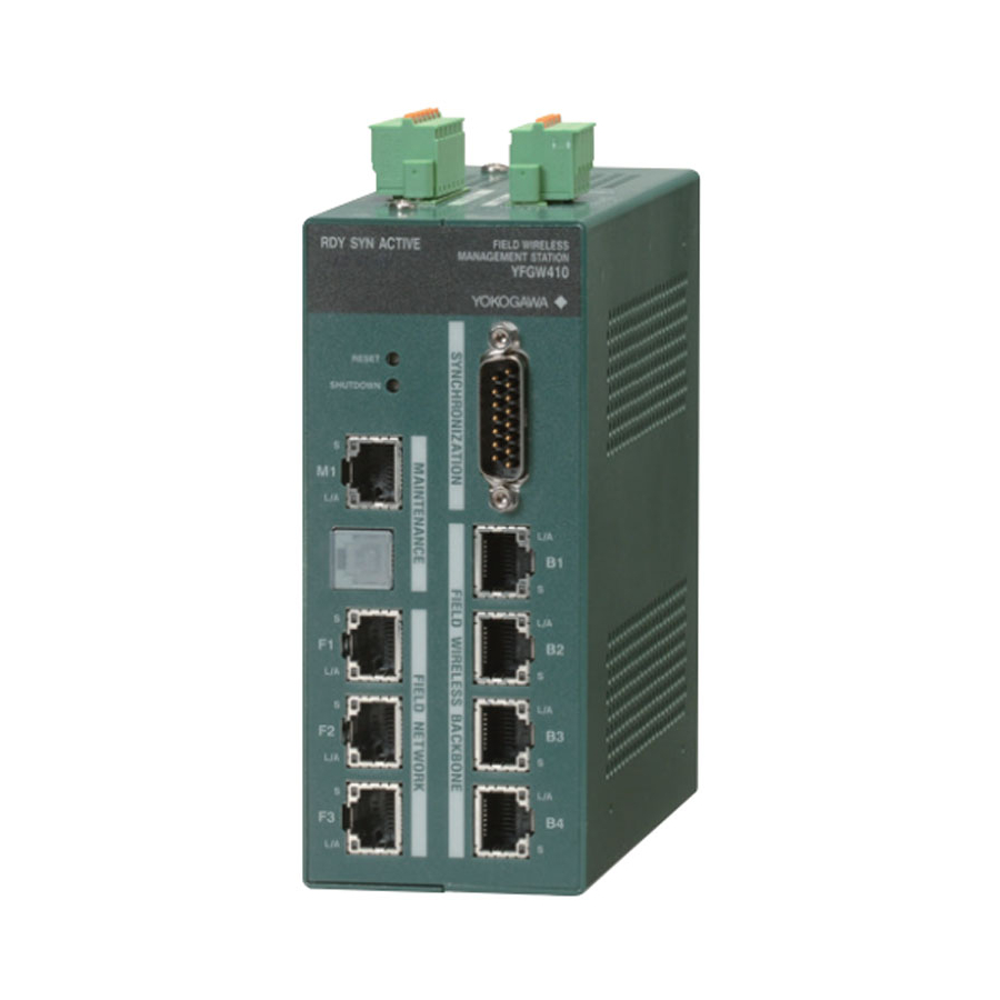
B3-1 <B3. Structure and Parts of YFGW410> B3. Structure and Parts of YFGW410 B3.1 Front View Power supply connector RS-485 connector Status indicator LED Reset switch Synchronization connector Shutdown switch Field wireless Maintenance interface backbone interface 1 Serial port Field wireless... -
Page 27: B3.3 Side And Rear Views
<B3. Structure and Parts of YFGW410> B3.3 Side and Rear Views Name plate DIN rail mounting bracket Right side Rear Left side FB0303.ai Figure B3-3 YFGW410 side and rear views B3.4 RS-485 Configuration Switches Top cover Switch number RS-485 configuration switches SW602 SW604 SW603... -
Page 28: B3.5 Outline Of Component Functions
Resets YFGW410. Hold the Reset switch for more than six seconds, the database in the YFGW410 is initialized. If the database is initialized, the entire setup information of the device is cleared. Always make a backup copy of the database before starting its initialization. -
Page 29: B4. Checking The Product
RS-485 connector Power supply connector DVD-ROM Read Me First YFGW410 Terminator or Cable for Redundancy FB0401.ai Figure B4-1 Checkout of delivered products ● Read Me First (IM01W02D01-11EN YFGW410 Field Wireless Management Station Read Me First) When specified manual language as an English. ● DVD-ROM (F9194TA) When specified Software Media as DVD-ROM. ● Terminator or Cable for Redundancy It depends on selection of Sync Connector Termination. If With Terminator is specified, Terminator is included. Otherwise Cable for Redundancy is included. -
Page 30: C1. Installation Environment
C1-1 <C1. Installation Environment> Part C Installation This part describes the installation of the YFGW410. Follow the steps below to use of the product. YFGW410 installation Power, ground, and signal cable connection C1. Installation Environment The system must be installed in an appropriate environment to ensure stable system operation. - Page 31 • The temperature specification during operation indicates the criterion of the temperature at the air intake of the bottom portion of modules. Do not block ventilation holes, as it may hinder the air-cooling capabilities of the body. When installing YFGW410 in a cabinet, note that the temperature specification is not in respect to the ambient temperature of the cabi- net. Provide cooling fans in the cabinet if needed.
- Page 32 C1-3 <C1. Installation Environment> Radio Device Noise to YFGW410 The following shows general requirements when using a radio device such as transceivers; however, as a general rule, close the cabinet door when using a radio device: • Transceivers that have 3 W of output power or less should be at least 1 m away. Transceiv- ers that have 10 W of output power or less should be at least 2 m away.
-
Page 33: C2. Power Supply And Grounding
• Please supply the power from the permanent power supply to avoid. IMPORTANT - YFGW410 does not have a power switch. Provide a breaker or switch for the external power line to turn ON/OFF the device. - The overcurrent protection circuit of the power supply, it is recommended to use the auto- matic-recover type with the reverse L-shaped. -
Page 34: C2.2 Grounding
Appropriate grounding is necessary for the stable operation of YFGW410. Class D grounding (the third class grounding) with the ground resistance of 100 ohms or less is necessary. To con- nect the ground cable to YFGW410 directly, use the frame ground (FG) terminal on the top side of the mainbody. -
Page 35: C3. Mounting
C3-1 <C3. Mounting> C3. Mounting YFGW410 can be mounted on the DIN rails, and it is usually mounted on the panel or wall in the cabinet. No other type of mounting is allowed. C3.1 Mounting Direction YFGW410 is designed to be cooled by natural air. Install an YFGW410 so that the ventilation air flows upward from its bottom to top as shown below. Mount in the correct direction. -
Page 36: C3.2 Mounting To Din Rails
Be careful that the rails do not get bent or deformed due to the weight of the YFGW410 or cable tension. To securely ground YFGW410, insert an insulation bushing between the DIN rails and mounting panel and tighten the screws. Insulate the DIN rails from the metal surface of the mounting panel. -
Page 37: C3.3 Installation Of The Yfgw410
As shown in Figure C3-3, hook the top edge of the DIN rail mounting bracket onto the top of the DIN rail, and return the YFGW410 back to the horizontal position. Then, hook the bottom edge of the mounting bracket onto the bottom of the DIN rail. - Page 38 C3-4 <C3. Mounting> FC0304.ai Figure C3-4 Mounting example FC0305.ai Figure C3-5 Mounting example (in redundant configuration) IM 01W02D01-01EN...
-
Page 39: C4. Wiring
YFGW410. C4.1 Terminals and Communication Ports Connection The YFGW410 has spring terminals to connect the power supply cable and serial communication cables. Use the screw to connect the ground terminal with a ring-type crimp to the frame ground. Use the RJ-45 connectors for Ethernet, and connect the metal network cables to the field wire- less backbone device interface, field network interface, and maintenance interface. -
Page 40: C4.2 Power Supply Cable Connection
To separate the terminal from the socket, loosening these screws. There is enough space for cabling at the top and side panels of the YFGW410, leave the spring terminals on the mainbody (as shown in Figure C4-2) and connect the positive and negative power lines as indicated. - Page 41 C4-3 <C4. Wiring> To disconnect the power supply cable from the spring terminal, push down the orange areas around the cable inlet and pull out the power supply cable from the socket. FC0403.ai Figure C4-3 Disconnecting the power supply cable Applicable cables Insulated cables for industrial equipment such as;...
- Page 42 C4-4 <C4. Wiring> Wiring to spring terminals:1 (without sleeve) - When using a solid conductor, strip the insu- lated cover and connect it. Cable Strip the solid conductor by 10 mm. - When using a stranded conductor, strip the insulated cover and twist and connect it. Core Length of exposed wire Strip the stranded conductor for 10 mm.
- Page 43 C4-5 <C4. Wiring> Table C4-1 List of power cables Cable Dimensions (mm) Phoenix Section Strip Contact's type area length (mm) 0.25 10.5 0.15 0.25 AI 0.25-6 BU 0.34 10.5 0.15 0.25 AI 0.34-6 TQ 12.5 0.15 0.25 AI 0.34-8 TQ 12.0 0.15 0.25...
-
Page 44: C4.3 Grounding
100 ohms or less is necessary. To connect the ground cable to YFGW410 directly, use the frame ground (FG) terminal (M4 screw) on the top side of the mainbody. Secure the M4 screws at a tightening torque of 1.2 to 1.5 Nm. YFGW410 should not share a ground wire with other devices. - Page 45 C4-7 <C4. Wiring> FC0407.ai Figure C4-5 Ground terminal connection procedure IM 01W02D01-01EN...
-
Page 46: C4.4 Communication Cable Connection
YFGW410. Generally, connect the host system which transmits data using the ISA100.11a protocol to the F1 port of YFGW410. Connect the host system which transmits data using the Modbus/TCP proto- col to the F2 or F3 port. - Page 47 Host System RS-485 Configuration Switches SW602 SW604 SW603 SW605 R1: Termination resistance of 120 Ω (comes with YFGW410) FC0409.ai R2: According to the instruction on the external equipment Figure C4-7 Connection and Configuration in 4-wire Type Connection in 2-wire Type YFGW410...
- Page 48 C4-10 <C4. Wiring> Maintenance interface Connect the 100BASE-TX compliance cable, terminated with an RJ-45 connector, to the main- tenance interface (M1) on the front panel of the YFGW410. Connect the Field Wireless Manage- ment Console to this port for configuration of a field wireless network and the YFGW410. IMPORTANT When CENTUM VP is running, set and adjust the parameters of the field wireless device from PRM. When CENTUM VP is not running, or when a non-Yokogawa host system is connected, the pa- rameters can be set and adjusted using FieldMate.
-
Page 49: C5. Explosion-Proof Wiring
C5-1 <C5. Explosion-Proof Wiring> C5. Explosion-Proof Wiring Be sure to read the precautions for the explosion-proof type product including wiring desribed in “YFGW410 Field Wireless Management Station Read Me First (IM 01W02D01-11EN)”. IM 01W02D01-01EN... -
Page 50: D1. Engineering Procedures
The explanations in this document are based on the assumption that all engineering in the net- work construction is executed after the delivery of the components for the Field Wireless System to the customer. When Yokogawa Electric Corporation receives an order that includes the engi- neering, the procedure may differ from the flow shown in Figure D1-1. - Page 51 Modbus registers. For the detailed procedures, see Sub-section D4.2.8 “Modbus Settings” in this document. The tasks of downloading information to the YFGW410 and verifying the startup and running sta- tus of the field wireless network are assumed to be performed by the wireless system engineer (including the start-up engineer) after the device has been delivered to the user’s plant site and installed.
- Page 52 When CENTUM VP R4 is used, R4.02.30 or higher is required. For details, see Reference Sub- system Communication (Using FIO) (IM 33M01A30-40E). When CENTUM VP R5 is used, R5.02.00 or higher is required. If CENTUM VP is used with YFGW410 in redundant configuration or writing output values to field wireless devices, CENTUM VP R5 is required. For details, see the Communication with Subsys- tem Using FIO user’s manual (IM 33K03L20-50E).
-
Page 53: D2. Tools To Be Used For The Engineering
D2.1 Overview of the Tools Configurator This tool is included in the Field Wireless Management Console that is built into the YFGW410. It is used for constructing the field wireless network. It creates the configuration information for the wireless network configuration that is managed by the YFGW410 based on the detailed design information of the wireless network. It also creates... -
Page 54: D2.2 Using The Field Wireless Management Console
01R01A01-01E). If the host system for YFGW410 is not CENTUM VP manufactured by Yokogawa and there is no PRM (mentioned later in this document), you can set the parameters by connecting a PC on which FieldMate is installed to maintenance interface of YFGW410. -
Page 55: D2.2.1 System Requirements
IE11 D2.2.2 Launching the Tool Connecting and launching YFGW410 When YFGW410 is factory default, before power on, connecting the power, synchronization con- nector and field network interface 1 is required. In addition, for a redundant configuration, two YFGW410s should be connected each other with Cable for Redundancy. The host system should be connected to field network interface 1, and the PC which executes the Field Wireless Management Console should be directly connected to maintenance interface. - Page 56 D2-4 <D2. Tools to be Used for the Engineering> IMPORTANT When launching YFGW410, if nothing is connected to field network interface 1, or if the connect- ed device is not running, YFGW410 may detect an error and may not launch properly. IMPORTANT The network should be configured that the PC which executes the Field Wireless Management Console can access to YFGW410 through a field network interface, during an operational state. PC settings • When connecting the PC to the maintenance interface The maintenance interface’s IP address at the time of shipment from the factory is...
- Page 57 The Field Wireless Management Console becomes usable about one minute after the RDY LED, which shows the running status of YFGW410, turns green. Depending on the status of the RDY LED, access to the Field Wireless Management Console may not be possible. For the status of the LED that shows the running status, see Section F2.2 Status Indicators and Actions.
- Page 58 D2-6 <D2. Tools to be Used for the Engineering> Unless .NET Framework specified in Sub-section D2.2.1 System Requirements is installed to the Windows PC , the following message will displayed and the application cannot be launched. In this case, install the appropriate .NET Framework to the PC. • Windows Server 2012 R2 FD0203.ai •...
- Page 59 D2-7 <D2. Tools to be Used for the Engineering> • Windows 7/Server 2008 R2 FD0206.ai When the application is successfully launched, the window shown in Figure D2-2 is displayed. FD0207.ai Figure D2-2 Login window Item Description Maximum number of Initial setting characters User Name Login user name...
- Page 60 OTA provisioning manager D5.2.8 IMPORTANT If Configurator and Monitor are launched at the same time, operations must not be run on them simultaneously due to the following operation conflicts. Start a new operation only after the cur- rently running one is completed. • Downloading the field wireless network settings (Configurator) • OTA provisioning (Monitor) • Downloading firmware (Monitor) • Reading device parameters (Monitor) • Restarting device (Monitor) • Changing active / standby status of YFGW410 (Monitor) IM 01W02D01-01EN...
- Page 61 When access control is enabled for the Field Wireless Management Console, the following error is displayed in a dialog if an attempt is made to launch Configurator or Monitor from an unpermit- ted IP Address:“Communication Error: Failed to send or receive data.” For details of access control, see Sub-section D4.2.1 YFGW410 Settings. Launching Configurator In the Field Wireless Management Console launch window, click the [Configurator] button to go to the Login window, and then enter a User Name and Password. After you have successfully logged in, the following window is displayed.
- Page 62 IMPORTANT If YFGW410 is unable to acquire the information when the window is updated due to causes such as a communication error, the following error is displayed in a dialog: “Communication Er- ror: Failed to send or receive data”. In such case, check the following items: •...
-
Page 63: D3. Provisioning
• Network ID The identifier of the field wireless network to which the field wireless device joins. Set a deci- mal value from 2 to 65535. • Join Key The Join Key is a 128-bit encryption key used for secure joining of the field wireless device. It is automatically generated by the provisioning. Provisioning methods supported by YFGW410 • OOB provisioning (Provisioning via infrared communication) You can perform the provisioning to the field wireless device which supports infrared com- munication by using FieldMate. FieldMate supports both OOB provisioning methods of “Uses a provisioning information file” and “Does not use a provisioning information file”. - Page 64 Guideline for choosing a provisioning method • If a field wireless device has an infrared communication port, use OOB provisioning stand- ardized by ISA100 Wireless Compliance Institute (WCI). • In general, use the method “Uses a provisioning information file”. In this method, the provisioning information of the device is utilized by downloading it to YFGW410. • In the case of the target field wireless device does not located at the same place as YFGW410 and the file sharing is not easy, you can use the method “Does not use a provisioning information file”. • Only when the target ISA100.11a Registered Device does not support infrared communica- tion, we recommend you to use OTA provisioning.
- Page 65 D3-3 <D3. Provisioning> Provisioning methods OOB provisioning Item Does not use OTA provisioning Uses a provisioning a provisioning information file information file By using FieldMate, By using FieldMate, perform OOB provision- By using Configura- (1) The work be- perform OOB provision- ing “Uses a provisioning tor, select the channel fore register- ing “Does not use a...
- Page 66 After that, by using Monitor, check that the device is connected to the network and that all the detailed information such as the communications quality is normal. IMPORTANT When performing OTA provisioning, it is required to clear provisioning information of the field wireless device in advance. Use FieldMate R3.01 or later to clear provisioning information of Yokogawa’s field wireless device. IMPORTANT By performing “Update Join Key” operation, the field wireless devices performed OOB provision- ing “Does not use a provisioning information file” will be the same status of the device performed OOB provisioning “Uses a provisioning information file”. Note that reset provisioning information of the device is required when the device will be connected to other gateways or different field wireless subnets.
-
Page 67: D4. Constructing A Field Wireless System
Tree pane item names Operation overview n YFGW410 Settings Set the device tag of the YFGW410 and the Layer2 switch of the Field Wire- less Backbone Network during YFGW410 redundant operation • Interfaces Set the IP addresses of the Field Wireless Backbone Network and mainte-... -
Page 68: D4.2 Detail Of Configuration
In addition, the [Use external Layer2 switch for Field Wireless Backbone Interface] check box in- dicates the use of the Layer2 switch. The default setting is displayed according to the YFGW410 redundancy settings. When the Layer2 switch is used with the Field Wireless Backbone Network, always select the check box while observing the important points listed in Chapter A4.YFGW410... - Page 69 When the setting information of these tabs is edited, all backbone devices must be restarted when the setting information is downloaded. Field Wireless Backbone When the YFGW410 is set for single operation and the [Field Wireless Backbone] tab is selected, the tab shown in Figure D4-1 appears in the main window. FD0401.ai...
- Page 70 + 1. It is necessary to set IP Address settings such that there is no overlap with other devices. Field Network1 When the YFGW410 is set for single operation and the [Field Network1] tab is selected, the tab shown in Figure D4-2 appears in the main window. FD0402.ai Figure D4-2 Field Network1 Setting Tab (for Single Operation) The IP address, subnet mask, default gateway address of Field Network1 are configured here.
- Page 71 Field Network2 and Field Network3. This will be explained using Field Network2 as an example. When the YFGW410 is set for single operation and the [Field Network2] tab is selected, the tab shown in Figure D4-3 appears in the main window.
- Page 72 D4-6 <D4. Constructing a Field Wireless System> When the YFGW410 is set for single operation and the [Field Network3] tab is selected, a win- dow similar to Figure D4-3 appears. The settings are the same as those for Field Network2. Configure the settings as necessary. Default settings are shown below. Item Description Default setting...
- Page 73 When the setting information of these tabs is edited, all backbone devices must be restarted when the setting information is downloaded. Field Wireless Backbone When the YFGW410 is set for redundant operation and the [Field Wireless Backbone] tab is selected, the tab shown in Figure D4-5 appears in the main window. FD0405.ai...
- Page 74 IP Address +1. It is necessary to set IP Address settings such that there is no overlap with other devices. Field Network1 When the YFGW410 is set for redundant operation and the [Field Network1] tab is selected, the tab shown in Figure D4-6 appears at the main page. FD0406.ai...
- Page 75 IMPORTANT Always connect the host system to Field Network1. Field Network2/3 When the YFGW410 is set for redundant operation and the [Field Network2] tab is selected, the tab shown in Figure D4-7 appears at the main page. FD0407.ai Figure D4-7 Field Network2 Setting Tab (for Redundant Operation)
- Page 76 UNIT2 connector of the cable for redundancy. (Used internally) Subnet Mask Subnet mask of Field Network2 255.255.255.0 When the YFGW410 is set for redundant operation and the [Field Network3] tab is selected, a window similar to Figure D4-7 appears. The settings are the same as those for Field Network2. Configure the settings as necessary. Default settings are shown below. Item...
- Page 77 In the access control list, IP address and subnet mask information of host systems (PCs run- ning applications, recording instruments, DCS I/O cards, etc.) that are permitted to access the YFGW410 can be registered and restrictions can be set for access to the YFGW410 by unregis- tered host systems or PCs.
- Page 78 D4-12 <D4. Constructing a Field Wireless System> When the [Add] button is clicked, the window shown in Figure D4-9 appears. FD0409.ai Figure D4-9 Access Control List Registration Window Two settings are available for the access control list setting: [IP Address] to configure the IP ad- dress, and [Network] to configure an individual network. In the window, select the button of the desired setting. The default setting is [IP Address]. When [IP Address] is selected, enter the IP address in the [IP Address] field. When [Network] is selected, enter the network address in the [Network Address] field and enter the subnet mask in the [Subnet Mask] field.
- Page 79 Figure D4-8. Time Source Setting the time source that YFGW410 uses. Time Source is the time standard to notify the host system from the Field Wireless Management Console and YFGW410. To synchronize the time of the YFGW410 and host system, acquire the time from a network time protocol (NTP) server that the host system uses.
- Page 80 IP address of the time server of the selected item can be entered manually. The default setting is the following address. IP Address: 192.168.0.200 IMPORTANT When the setting information of this tab is edited, YFGW410 must be restarted when the setting information is downloaded. IM 01W02D01-01EN...
-
Page 81: D4.2.2 Operation Mode
D4-15 <D4. Constructing a Field Wireless System> D4.2.2 Operation Mode The Field Wireless System supports one operation mode (Expert Mode) only. When [Operation Mode] is selected in the menu tree in the left pane of the Configurator, the tab shown in Figure D4-13 appears in the main window. FD0413.ai Figure D4-13 Operation Mode Tab At this tab, [Expert Mode] is selected. No operations can be performed at this tab. D4.2.3 Hopping Patterns Field Wireless System uses the frequencies of 16 channels in the range of 2.4000 to 2.4835 GHz... - Page 82 D4-16 <D4. Constructing a Field Wireless System> FD0414.ai Figure D4-14 Hopping Pattern Setting Tab At the bottom of the main window, select the wireless channels to be used to automatically gener- ate a hopping pattern. At the top of the main window, configure the [Channels for advertisements] setting. Channels for advertisements are wireless channels to add the new wireless devices to the field wireless network. Generally, the default channels do not need to be changed. Channels for advertisements Set the channels for advertising transmission.
- Page 83 If selecting 2 Hopping Patterns, more than 15 Enable Channels are required, and all Enable Channels should be same for each Hopping Pattern. IMPORTANT When the setting.information of this tab is edited, YFGW410 must be restarted when the setting information is downloaded. Hopping Pattern Table Items...
- Page 84 D4-18 <D4. Constructing a Field Wireless System> FD0415.ai Figure D4-15 Field wireless channels and wireless LAN channels window Usable wireless channels are regulated by national radio standards. With field wireless, 16 chan- nels between 11 and 26 can be used. However, the default setting is FCC (US), which removes channel 26 because it cannot be used. The 15 channels between channel 11 and 25 that are permitted in most countries are selected.
- Page 85 D4-19 <D4. Constructing a Field Wireless System> FD0417.ai Figure D4-17 Optimization Calculation Result Window This window shows the results of optimization for each pattern and indicates whether all patterns were optimized successfully. Button name Operation This button appears when all patterns were successfully optimized. Accept When this button is clicked, the window switches from the Optimized results window to the Hopping Pattern tab, and the [Optimization] check boxes are cleared.
-
Page 86: D4.2.4 Field Wireless Networks
D4.2.4 Field Wireless Networks When [Field Wireless Networks] is selected in the menu tree of the Configurator, the tab shown in Figure D4-18 appears in the main window. FD0418.ai Figure D4-18 Field Wireless Network Setting Tab At this tab, configure the settings of the field wireless subnets connected under the YFGW410. The default setting is to register a field wireless subnet with a Network ID of 100. When the net- work ID of the field wireless subnet is registered here, Network ID:100 (when the default setting is used) appears under [Field Wireless Networks] in the menu tree of the window. Button name Function When this button is clicked, the window shown in Figure D4-19 appears. - Page 87 D4-21 <D4. Constructing a Field Wireless System> • Add a field wireless subnet When the [Add] button is clicked, the window shown in Figure D4-19 appears. FD0419.ai Figure D4-19 Add Field Wireless Subnet Window When the [Network ID] field is entered and the [OK] button is clicked, it is added to the list in the main window and under [Field Wireless Networks] in the menu tree. The Network ID setting range is a decimal number between 2 and 65535.
- Page 88 D4-22 <D4. Constructing a Field Wireless System> Field Wiress Subnet Settings (Network ID:100) When [Network ID:100] (when the default Network ID setting) is selected under [Field Wireless Networks] in the menu tree of the Configurator, the [Network Information], [Backbone Routers], and [Field Devices] tabs appear in the main window. Field Wiress Subnet Information (Network Information) When the [Network Information] tab is selected, the tab shown in Figure D4-21 appears.
- Page 89 D4-23 <D4. Constructing a Field Wireless System> Backbone Routers When the [Backbone Routers] tab is selected, the tab displayed in Figure D4-22 appears. FD0422.ai Figure D4-22 Backbone Router Tab (Initial Condition) At this tab, register Field Wireless Access Point that comprise the field wireless subnet. Button functions Button name Function Add YFGW510. The window shown in Figure D4-23 appears. Edit registered information of selected YFGW510.
- Page 90 When automatic allocation of the IP address was selected using Automatically the setting at the [Field Wireless Backbone] window after selecting allocated in as- IP Address [YFGW410 Settings] and [Interfaces], the displayed IP address cending order from cannot be changed. 192.168.200.111 Configure whether to use the factory default password. It must...
- Page 91 D4-25 <D4. Constructing a Field Wireless System> After the settings and changes are complete and the [OK] button is clicked, the information of the Backbone Router Settings window is added to the setting chart of the main window. When the [Cancel] button is clicked, the information at the Backbone Router Settings window is discarded.
- Page 92 D4-26 <D4. Constructing a Field Wireless System> In the example shown in Figure D4-25, 2 YFGW510s in the Network ID:100 field wireless subnet have a Duocast setting and are registered to use the default password. FD0425.ai Figure D4-25 Backbone Routers Registration Example Field Devices When the [Field Devices] tab is selected, the tab shown in Figure D4-26 appears. In the default status, the chart does not contain any registered items.
- Page 93 D4-27 <D4. Constructing a Field Wireless System> At this tab, register field wireless devices to be allocated under the field wireless backbone. Button functions Button name Function When the device is provisioned by using OOB provisioning “Does not use a provisioning information file” or provisioned at the factory or provisioned via OTA provisioning, click this button to add the device. When a field wireless device that requires additional or changed functions settings is se- lected and this button is clicked, the window shown in Figure D4-27 appears. Perform the Edit necessary changes at this window.
- Page 94 D4-28 <D4. Constructing a Field Wireless System> Item Description Default setting Network ID Automatically display the ID of the field wireless subnet. Automatic setting Device Tag Display the device tag of the field wireless device set dur- DEV001 ing provisioning. OTA Provisioning To let the device join to the field wireless network by using Check box cleared OTA provisioning, select the check box. (Don’t execute OTA provisioning) EUI-64 64-bit Extended Unique Identifier. Acquired during provi- Blank sioning.
- Page 95 In addition, devices with an IO(Auto) role are automatically set to the optimal connection destina- tion at this time by the YFGW410 when joining the wireless network. Even in such cases, devices with a routing function (devices with a IO+Router or Router role) must have a host device manu- ally selected and hopping limited to three times.
- Page 96 D4-30 <D4. Constructing a Field Wireless System> Registering from a provisioning fi le When the [Import Provisioning File] button is clicked, the window shown in Figure D4-28 appears. FD0428.ai Figure D4-28 Open Provisionng File Window In this window, select the provisioning fi le (the fi le extension is .ypif) that includes the information of fi eld wireless devices to be registered to import it.
- Page 97 D4-31 <D4. Constructing a Field Wireless System> FD0429.ai Figure D4-29 Import Provisioning File Window When the [OK] button is clicked, the information is added to the device registration list as shown in Figure D4-30. When the [Cancel] button is clicked, new devices are not registered and the confirmation window is closed.
- Page 98 D4-32 <D4. Constructing a Field Wireless System> If the field wireless devices tab already contains information of registered devices when the pro- visioning file information is imported, a window shown in Figure D4-31 appears instead of Figure D4-29. FD0431.ai Figure D4-31 Import Provisioning File Window The [Older Devices] column of the import provisioning file window displays the device tag that have already been registered to the field devices tab included in the provisioning file. Not all device check boxes are selected. Check boxes of devices to be updated by the provisioning information are selected. In this example, the window indicates that all 8 devices included in the provision file are already registered and the check box of YTA-4 is selected.
- Page 99 D4-33 <D4. Constructing a Field Wireless System> FD0432.ai Figure D4-32 Import Result Dialog After the information has been imported to the device registration list, the dialog shown in Figure D4-32 appears. Click the [OK] button to close this window. This window indicates that 1 field wire- less device was updated in this example. Figure D4-33 shows the results of importing the information of 8 field wireless devices from the provisioning file to the wireless device registration list. FD0433.ai Figure D4-33 Field Devices Tab after Registering from Provisioning File IM 01W02D01-01EN...
- Page 100 D4-34 <D4. Constructing a Field Wireless System> Device registration list items Item Description Default setting Device Tag Device tag of the field wireless device EUI-64 64-bit Extended Unique Identifier Read from the provisioning file (*1) Encryption key when adding a field wireless device to the Join Key network Device Role Role of the field wireless device IO (Auto) The routing device in the primary path is set by the device Primary Router Blank The routing device in the secondary path is set by the...
-
Page 101: D4.2.5 Graphic Editor
D4-35 <D4. Constructing a Field Wireless System> D4.2.5 Graphic Editor The graphic edit function allows you to position wireless devices on a map or floor plan of the installation area so that you can visually confirm transmission paths. You can also observe the connections status of YFGW510 and field wireless devices set in the image using the Monitor of the Field Wireless Management Console. When [Graphic Editor] is selected in the menu tree of the Configurator, the tab shown in Figure D4-34 appears in the main window. FD0434.ai Figure D4-34 Graphic Editor Tab Button name Function Set the information of the area information to be newly registered. Edit Edit the information settings of the area information. - Page 102 D4-36 <D4. Constructing a Field Wireless System> Adding area information When the [Add] button is clicked, the window shown in Figure D4-35 appears. FD0435.ai Figure D4-35 Area Settings Window Item Description Default setting Set an area name. The default setting can be Allocated in ascending order from Area Name changed.
- Page 103 D4-37 <D4. Constructing a Field Wireless System> Editing area information When the row of information to be updated is double clicked or the row is selected in the list and the [Edit] button is clicked, the shown in Figure D4-35 appears. Make the necessary corrections or revisions.
- Page 104 Icon Name Operation scope YFGW410 Indicates a YFGW410. It cannot be allocated in the backgroud image area. Indicates a Field Wireless Access Point with a backbone router role. Al- Backbone Router locate registered devices on the backgroud image area. Indicates devices with Router or IO+Router roles. Allocate registered de- Routing Device vices on the backgroud image area.
- Page 105 D4-39 <D4. Constructing a Field Wireless System> FD0438.ai Figure D4-38 Backbone Router Allocation Allocating Routing Devices A routing device is a field wireless device with a Router or IO+Router role. Drag and drop the routing device icon at the bottom of the main window to the installation position on the background image area. The shown in Figure D4-39 appears. FD0439.ai Figure D4-39 Select Device Tag Window IM 01W02D01-01EN...
- Page 106 D4-40 <D4. Constructing a Field Wireless System> Item Description Default setting Automatically displays the network ID set for the area Network ID Automatically displayed displayed. The device tags of field wireless devices with routing func- Displays registered unal- tion registered with the relevant network ID are displayed in Device Tag located devices in ascend- the drop-down box.
- Page 107 D4-41 <D4. Constructing a Field Wireless System> Allocating Device Groups To add a device group, drag and drop the device group icon at the bottom of the main window to the installation position on the background image area. The window shown in Figure D4-41 ap- pears.
- Page 108 D4-42 <D4. Constructing a Field Wireless System> FD0442.ai Figure D4-42 Edit Device Group Window When the information does not need to be edited, click the [OK] button. The wireless device group is added in the condition displayed on the backgroud image area. If the transmission path host devices must be changed, edit the settings and click the [OK] but- ton to update the information.
- Page 109 D4-43 <D4. Constructing a Field Wireless System> Item Description Default setting Set the size of the comment characters (in points) Select Size the setting from the drop-down box. Color Set the character color. Black Enter a comment. Up to 16 half-byte alphanumeric charac- Text Comment ters can be entered.
- Page 110 D4-44 <D4. Constructing a Field Wireless System> Manipulating and changing the backgroud image area Figure D4-45 shows the result of all examples of adding information to the eight wireless devices registered at Figure D4-32. FD0445.ai Figure D4-45 Area Registration Example Buttons in the area setting tab and their functions Button name Function...
- Page 111 D4-45 <D4. Constructing a Field Wireless System> When the [Auto Paths] button is clicked, the window shown in Figure D4-46 appears in the main window. FD0446.ai Figure D4-46 Auto Path Settings Window The automatic path settings window appears. The transmission paths of IO field wireless devices with selected check boxes are automatically recalculated. Recalculation calculates that distance between the icons based on the positions of the device icons allocated on the backgroud image area.
- Page 112 D4-46 <D4. Constructing a Field Wireless System> FD0447.ai Figure D4-47 Path Settings Window Item Description Default setting The start point device of the selected path. Start Point It cannot be edited. Automatically displays the The end point device of the selected path. configured information of End Point Select the setting from the drop-down box.
-
Page 113: D4.2.6 Alert Settings
D4-47 <D4. Constructing a Field Wireless System> D4.2.6 Alert Settings At this tab, set the tolerances for the warning operations used by the Monitor, which observes the operation status of the field wireless network. When [Alert Settings] is selected in the menu tree of the Configurator, the tab shown in Figure D4-48 appears in the main window. FD0448.ai Figure D4-48 Alert Settings Tab Setting items Default Item... -
Page 114: D4.2.7 Sampling Data
D4-48 <D4. Constructing a Field Wireless System> D4.2.7 Sampling Data At this tab, configure the publication of process values and diagnosis data from field wireless devices to host systems. When [Sampling Data] is selected in the menu tree of the Configurator, the tab shown in Figure D4-49 appears. FD0449.ai Figure D4-49 Sampling Data Tab Information displayed in the sampling data list Default Item Description setting The name of the data exchanged with the host system. List rows are Sampling Data displayed in ascending order by data name. - Page 115 D4-49 <D4. Constructing a Field Wireless System> Adding sampling data When the [Add] button in Figure D4-49 is clicked, the window shown in Figure D4-50 appears. FD0450.ai Figure D4-50 Sampling Settings Window Initial Item Description settings Device tag name of the device whose information is displayed in Device Tag this window.
- Page 116 D4-50 <D4. Constructing a Field Wireless System> FD0451.ai Figure D4-51 CF File Drop-down Box at Sampling Settings Window The default condition of the drop-down box has two items: [Load CF/DD] and [Delete CF/DD]. To register on new CF fi le here, select [Load CF/DD], and then select the CF fi le of the model to be registered at the window shown in Figure D4-52. FD0452.ai Figure D4-52 Selection Window to Register CF Files IM 01W02D01-01EN...
- Page 117 D4-51 <D4. Constructing a Field Wireless System> The folder and file names for CF files have the following format. Therefore, it is necessary to select a file that matches the revision of the model to be registered. <Vendor ID>\<Model ID>¥<Device Revision><DD Revision><CF Revision>.cff IDs of Yokogawa Field Wireless Devices Item Description Vender ID 00594543 000C 0005 YTMX 1802 Model ID FN310 (HART Communication) 2000 FN310 (SENCOM) 2001 FN510 (AI, DIDO, PULSE) 2002 When the [OK] button is clicked, the window shown in Figure D4-53 appears.
- Page 118 D4-52 <D4. Constructing a Field Wireless System> FD0453.ai Figure D4-53 Sampling Settings Window after Loading CF File When [Delete CF/DD] is selected from the CF File drop-down box, the window shown in Figure D4-54 appears. FD0454.ai Figure D4-54 Delete CF File Window When a CF file to be deleted is selected from the drop-down box and the [OK] button is clicked, the registration is deleted.
- Page 119 D4-53 <D4. Constructing a Field Wireless System> • Registering sampling data When the button to the right of the Device Tag field at the sampling settings window is clicked, the window shown in Figure D4-55 appears. FD0455.ai Figure D4-55 Select Devices Window When selecting the [Network ID] in select devices window, field wireless devices can be regis- tered into field device list information. Devices to register sampling data have their check boxes selected to the left of the device tag. The same model can be registered at same time.
- Page 120 D4-54 <D4. Constructing a Field Wireless System> When a new registration is made, no Modbus Settings are affected. When the [OK] button of the warning dialog is clicked, the parameter information of devices regis- tered to the [Read Parameters] tab and [Write Parameters] tab of the sampling settings window is registered.
- Page 121 D4-55 <D4. Constructing a Field Wireless System> The [Read Parameters] tab is comprised of Available Parameters and Read Parameters sec- tions. When a new registration is made, all Available Parameters are registered under Parameters in the Read Parameters section, and mapping to the Modbus Register can be performed. Content of the Available Parameters tree First level: UAP ID Second level: Object Name + Block Description...
- Page 122 The setting range is from 0 to 3,600 seconds. When 10 Sec “0” is selected, there is no publication. Set the time for a YFGW410 to determine transmission error. Set Stale Limit (Times) a multiple of the Publication Period setting. Select a setting from 1 10 Times to 255 from the drop-down box.
- Page 123 D4-57 <D4. Constructing a Field Wireless System> IMPORTANT Always register the CF file, even when data is not published periodically. Alternatively, set Publi- cation Period to “0”. IMPORTANT For periodic data publication, set an update time in the range that can be used by the field wire- less device. The composition of the [Write Parameters] tab is the same as that of the [Read Parameters] tab, excluding the items below. Content of the Available Parameters tree First level: UAP ID Second level: Object Name + Block Description Third level: Attribute Name...
- Page 124 D4-58 <D4. Constructing a Field Wireless System> FD0463.ai Figure D4-59 Example of Registration at the Sampling Setting Tab Updating sampling data When information registered in the list at the [Sampling Data] tab is selected and the [Edit] button is clicked, the sampling settings window appears and displays the information currently regis- tered.
-
Page 125: D4.2.8 Modbus Settings
D4-59 <D4. Constructing a Field Wireless System> D4.2.8 Modbus Settings When [Modbus Settings] is selected in the menu tree of the Configurator, the tab shown in Figure D4-60 appears. FD0464.ai Figure D4-60 Modbus Settings Tab The main window is comprised of three tabs: [Modbus Settings], [Input Registers], and [Holding Registers]. Modbus Settings Tab When the [Modbus Settings] tab is selected, the tab shown in Figure D4-60 appears. At this tab, configure the Modbus mapping type and read parameter assignment. - Page 126 D4-60 <D4. Constructing a Field Wireless System> FD0465.ai Figure D4-61 Change Warning Dialog When the [OK] button is clicked, the change is applied. All existing mapped settings are dis- carded at this time. When the [Cancel] button is clicked, no changes are made and the dialog is closed.
- Page 127 D4-61 <D4. Constructing a Field Wireless System> Parameters can be allocated to Input Registers are as follows. Data size (word) Parameter name Description Data status Data Notification of YFGW410 GW_STATUS status Notification of backbone BBR_STATUS router status Notification of field wireless DEV_STATUS device status Notification of self-diagnosis UAPMO.DIAG_STATUS information of the field wire- less device AI_xx(“BLOCK_DESCRIPTION”).PV...
- Page 128 D4-62 <D4. Constructing a Field Wireless System> For Normal Mapping The status and value of the parameters which send to a host system can be combined and mapped. The first time the [Input Registers] tab is opened at the [Modbus Settings] tab, GW_ STATUS is already positioned at the top (0 to 8). The allocation position of GW_STATUS can be changed by dragging it in the [Input Registers] list.
- Page 129 D4-63 <D4. Constructing a Field Wireless System> In this example, GW_STATUS is allocated to register numbers 0 through 8, and BBR_STATUS of BBR002 is allocated to register numbers 18 through 26. In this case, the [Available Parameters] section of the [Input Registers] tab is configured as fol- lows. Items displayed in the tree First level : Device tag name Second level : Device status (GW_STATUS, BBR_STATUS, and DEV_STA-...
- Page 130 D4-64 <D4. Constructing a Field Wireless System> The list is comprised of a column of registers numbers starting from 0 and a column of parameter names. Areas in which process values are allocated are light blue and areas in which statuses are al- located are light pink. The first row of the addresses contains the parameter name.
- Page 131 The order of the auto mapping follows rules in the chart. Parameter Normal Mapping Data Type Mapping GW_STATUS (YFGW410) 0 to 8 (Reserve 9 to 29) 0 to 7 (Reserve 8 to 29) BBR_STATUS 30 to 389 (Reserve 390 to 499)
- Page 132 D4-66 <D4. Constructing a Field Wireless System> Holding Registers Tab When the [Holding Registers] tab is selected, the tab shown in Figure D4-65 appears. FD0471.ai Figure D4-65 Holding Registers Tab The [Holding Registers] tab is comprised of two sections: Available Parameters and Holding Registers.
- Page 133 D4-67 <D4. Constructing a Field Wireless System> When selecting Input Registers in [Read Parameter Assignment], registered devices with write parameters are displayed in the [Available Parameters] section in the following format. First level : Device tag name Second level : Field wireless device UAP ID Third level : Field wireless device parameter name...
-
Page 134: D4.2.9 Resource
For details, see “Input Registers Tab” in this sub-section. The host system can write a data to a wireless field device, by writing the data and status part of the write parameter allocated in the holding register of YFGW410. YFGW410 sends the data to the device when the case of the value of the status is GOOD. The host system should write the data to the write parameter within the data publication period even if the value of the data does not change. - Page 135 D4-69 <D4. Constructing a Field Wireless System> Network The network ID of the field wireless network and the resource usage rate (%) of that field wireless subnets are displayed in the resource tab. Devices can be added as long as the usage rate does not exceed 100%. After configuring new settings or changing settings of the Configurator, perform an error check of the wireless network before selecting [Resource]. To perform an error check, click [Tools] and then click [Error Check]. When the check is complete, the window shown in Figure D4-67 appears.
- Page 136 D4-70 <D4. Constructing a Field Wireless System> Device When the [Device] tab is selected, the tab shown in Figure D4-68 appears in the main window. At this tab, the usage rate of the wireless band of each field wireless device is displayed. FD0475.ai Figure 4-68 Device Tab The Device Tab shows the following items. Item Description Device Resource List Backbone routers and field wireless devices are displayed. The field wireless...
- Page 137 D4-71 <D4. Constructing a Field Wireless System> Device Resource List The Device Resource List shows the following items. Item Description ID of the device used for tracking DL_Route1 and DL_Router2 Device Tag Device tag of the device Device Role Role of the device (IO / IO+Router / Router / BBR) Network ID ID of the field wireless subnet...
-
Page 138: D4.2.10 Downloading Wireless Network Settings
Correct the relevant items. Download When downloading from the default setting condition After using the Confi gurator to confi gure the fi eld wireless network, download the setting informa- tion to the YFGW410. All information of the YFGW410, YFGW510, and fi eld wireless devices is downloaded, but the YFGW510 and fi eld wireless devices do not need to be running. When the YFGW510 and fi eld wireless devices are running, the setting information is automatically downloaded from the YFGW410. To check the compatibility of the setting information with the setting rules, click [Tools], and then click [Download] in the menu bar of the Confi gurator. Alternatively, click the download icon [ ] in... - Page 139 FD0478.ai Figure D4-69 Start Download Warning Dialog When the [OK] button is clicked, downloading to the YFGW410 starts. When the [Cancel] button is clicked, the warning dialog is closed. When the download is complete, the window shown in Figure D4-70 appears.
- Page 140 D4-74 <D4. Constructing a Field Wireless System> FD0479.ai Figure D4-70 Download Progress Window When the [OK] button of the confirmation window is clicked, the window is closed and the window shown in Figure D4-71 appears. FD0480.ai Figure D4-71 Download Result Window Confirm that the results of all download processes are OK, and then click the [Close] button to close this window. IM 01W02D01-01EN...
- Page 141 When changing settings and downloading in an operational state Be aware of the following points when changing and downloading settings after starting operation of the field wireless network. • While YFGW410 communicates to set a publish configuration to field wireless devices, the configuration download may be failed. To avoid this, confirm that the status of the target field wireless devices that are changed configuration are Published, then execute the configura- tion download. • When deleting a routing device or changing a role from router, devices which is connected under target routing device will leave from the network. If IO (Auto) device is used, confirm...
- Page 142 File Menu The File menu has the following six items. [Backup], [Restore], [Export Configuration Data], [Export Modbus Registers], [Import Modbus Registers], and [Exit] Backup This function backs up the wireless network setting information created by the Configurator of the YFGW410 to a file. When [File] and then [Backup] are clicked, the window shown in Figure D4-72 appears. FD0481.ai Figure D4-72 Save Backup File Window IM 01W02D01-01EN...
- Page 143 D4-77 <D4. Constructing a Field Wireless System> When the file name and storage location are specified and the [Save] button is clicked, the win- dow shown in Figure D4-73 appears. When the [Cancel] button is clicked, the save backup file window is closed. FD0482.ai Figure D4-73 Backup Window At this window, encryption and a password can be added to the backup file. The default setting is [Only Encryption]. When [Encryption with Password] is selected, the pass- word fields become available. Enter a password into the File password and the Retype password fields. Up to 16 half-byte alphanumeric characters and symbols can be entered. When the [OK] button is clicked, a file of the field wireless network settings is saved. When the [Cancel] button is clicked, the window is closed.
- Page 144 D4-78 <D4. Constructing a Field Wireless System> Select a file with the extension [.bkup] and then click the [Open] button. The configuration data is imported into the Configurator. When the [Cancel] button is clicked, the window is closed. If the backup file has a password, the window shown in Figure D4-75 appears when the [Open] button is clicked. FD0484.ai Figure D4-75 File Passowrd Window Enter the password specified when the configuration data was backed up, and then click the [OK] button. The configuration data is imported. When the [Cancel] button is clicked, the window is closed and the backup file is not imported. Click the [Restore] button after confirming that all items are checked. Selecting restore items is for the use of service personnel and is not required for ordinary inspection and management. Export Configuration Data ...
- Page 145 Check the errors in the setting information. To perform an error check, click [Tools] and then click [Error Check]. For details, see Sub-section D4.2.10. Downloading Wireless Network Settings Download Download field wireless network settings to the YFGW410, YFGW510, and field wireless de- vices. For details, see Sub-section D4.2.10 Downloading Wireless Network Settings. Change password ...
- Page 146 D4-80 <D4. Constructing a Field Wireless System> The User Name field displays the name of the user logged into the Configurator. Enter the current login password in the Old Password field. Enter at the new password in the New Password and Retype Password fields. For privacy, characters entered into the password fields are displayed as asterisks [*]. Up to 16 half-byte alphanumeric and non-alphanumeric characters (Ex. !,$,#,%) can be entered. When the [OK] button is clicked, the password is changed and the window closes. When the [Cancel] button is clicked, the password is not changed.
- Page 147 D4-81 <D4. Constructing a Field Wireless System> • Add New User When the [Add New User] button is clicked in the window shown in Figure D4-78, the win- dow shown in Figure D4-79 appears. FD0488.ai Figure D4-79 Add New User Window Fill in the [User Name], [Authority], [Password], and [Retype Password] fields and then click [OK].
- Page 148 <D4. Constructing a Field Wireless System> Time settings Set the system time and time zone for the YFGW410. When [Tools] and then [Time Settings] are clicked, the window shown in Figure D4-81 appears. FD0490.ai Figure D4-81 Time Settings Window...
- Page 149 D4-83 <D4. Constructing a Field Wireless System> Help The Help menu contains the [About] item. When [Help] and then [About] are clicked, a window shown in Figure D4-82 appears. This win- dow shows the application version number and license usage status. FD0491.ai Figure D4-82 Version and Lisence Information Window [Export] button is for the use of service personnel, and is not required for ordinary inspection and...
-
Page 150: D5. Starting Up The Field Wireless System
Field wireless device (devices with only IO function) For 4 and 5 , start devices physically closer to YFGW510 first. Power on YFGW410, and wait approximately 1 minute after the RDY LED has lighted up green, then start the Monitor of the Field Wireless Management Console. The Monitor will show the status of wireless communications. -
Page 151: D5.2 Wireless Network Management
LAN) may lead to deterioration. To keep a stable field wireless network, requires regular status monitoring and maintenance of the wireless network. The Monitor in the Field Wireless Management Console built into YFGW410 is used for monitor- ing status and management of the wireless network and devices. D5.2.1... - Page 152 Log Viewer Topology Viewer Graphic Viewer Device detailed information (Property) YFGW410, YFGW510 Field wireless device Check the detailed information of each device FD0501.ai Figure D5-1 Relations among Monitor Functions A procedure of monitoring the field wireless network is following. • Check the status of devices by the Device List.
-
Page 153: D5.2.2
Click on a device icon or communications path to show details. Display the status of the field wireless backbone devices Backbone Device List (YFGW410, YFGW510). Click on the row for a particular device to show details. Display the status of the field wireless devices. Click on the Field Device List row for a particular device to show details. - Page 154 The information on the right side of the tool bar shows the following information. Line 1: Connected YFGW410 device tag. The connection status or operating mode of YFGW410 Line 2: YFGW410 time Line 3: Refresh button and user name...
-
Page 155: D5.2.3 Graphic Viewer
FD0503.ai Figure D5-3 Graphic Viewer Window The following icons appear on the background, depending on the function and status of the devices. Device with Device with Device Device status YFGW410 YFGW510 router Icon color IO function group function Normal Cyan... - Page 156 • Any of the F1 to F3 port in operation causes link-down. Each threshold value is set Warning • The communication from YFGW510 to YFGW410 is inter- by the Configurator. rupted • The received signal strength indication (RSSI) of wireless LAN is worse than the threshold value.
- Page 157 D5-8 <D5. Starting up the Field Wireless System> Device properties The information is different for YFGW410, YFGW510, or a field wireless device, so Each informa- tion is described separately. Field wireless device Double click the field wireless device icon on the window to display the information shown in Figure D5-4. FD0504.ai Figure D5-4 Field Wireless Device Properties Window Following table shows each item of the field wireless device information. These items are dis- played only and cannot be changed. Item Description Device Tag...
- Page 158 D5-9 <D5. Starting up the Field Wireless System> To close the properties window, click the [Close] button. Field Wireless Access Point Double click the backbone router icon on the window to display the information shown in Figure D5-5. FD0505.ai Figure D5-5 Backbone Device Properties Window Following table shows each item of the field wireless access point information. These items are displayed only and cannot be changed.
- Page 159 YFGW410 Double click the YFGW410 icon on the window to display the information shown in Figure D5-6. The window includes two tabs: the [General] tab and the [Interface Status] tab. Select the [Gen- eral] tab to display the window shown in Figure D5-6.
- Page 160 Select the [Interface Status] tab to display the window shown in Figure D5-7. FD0507.ai Figure D5-7 YFGW410 Properties Window (Interface Status) The items displayed on the [Interface Status] tab are as follows. These items are displayed only and cannot be changed.
- Page 161 D5-12 <D5. Starting up the Field Wireless System> Device group Double click the device group icon on the window to display the information shown in Figure D5- FD0508.ai Figure D5-8 Device Group Window The device group ID is shown on the title of the window. At the upper part of the window, the device group connection information appear.
- Page 162 D5-13 <D5. Starting up the Field Wireless System> Communications paths Double click the communications path on the window to display the information shown in Figure D5-9. This window shows the path properties. FD0509.ai Figure D5-9 Communication Path Properties Window The title of window shows summary of the communications path like [Lower device tag] >>...
-
Page 163: Other Functions
Field Device List. The functions that can be used depend on the device type as follows. Backbone devices Field wireless Function Summary device YFGW510 YFGW410 Display device detail informa- Device Properties tion Candidate Neighbors Display neighbor devices ... - Page 164 D5-15 <D5. Starting up the Field Wireless System> Displaying device properties Select [Device Properties] in the pop-up menu to open the window. For detail information, see “Device Properties” in this sub-section. Displaying candidate neighbors This function displays devices located in the vicinity which are not being used as primary or sec- ondary path devices, but which are path candidate devices for which the received signal strength indication is at least at a usable level.
- Page 165 D5-16 <D5. Starting up the Field Wireless System> Restart device This function provides to restart devices within the network forcely. When there is an operation fault or problem in a device or communications path, this function may correct it. Before execut- ing this function, must consider impacts on other devices and/or the host system.
- Page 166 [Restart Device] in the pop-up menu (same as Figure D5-13). IMPORTANT In a redundant configuration, do not restart YFGW410 during SYN LED is blinking. The system will be stop and YFGW410 will generate a fault status. To recover, it is necessary to power off the YFGW410 then power on again, so the operating status of the YFGW410 should be checked before restarting.
- Page 167 D5-18 <D5. Starting up the Field Wireless System> Reading out device parameters (Read Object Attribute) This function provides to read a device parameter specified ISA100.11a standard or device ven- dor by manual. It requires three IDs to read: TSAP, Object and Attribute. For the IDs to read out parameters, refer to the user’s manual for the field wireless device. Select [Read Object Attribute] in the pop-up menu to open the window shown in Figure D5-14. FD0514.ai Figure D5-14 Read Object Attribute Window Enter the TSAP ID, Object ID, and Attribute ID for the parameter to be read, and click the [OK]...
- Page 168 D5-19 <D5. Starting up the Field Wireless System> As the result, the window shown in Figure D5-15 appears. FD0515.ai Figure D5-15 Read Object Attribute Results Window The results of reading out are shown both in binary and ASCII formats. The figure shows the sen- sor firmware version as an example. Click the [Close] button to close the window. If the parameter reading fails, a dialog appears: “Communication error: Failed to access data- base.”...
- Page 169 After switching Active/Standby status, communica- tions between the Monitor and YFGW410 may be closed, and a dialog appears with message “Communication Error: Failed to send or receive data”, and the connection status is changed to [Offline]. After a short wait the Monitor will reconnect at the next refresh timing.
-
Page 170: D5.2.4 Topology Viewer
D5-21 <D5. Starting up the Field Wireless System> D5.2.4 Topology Viewer The Topology Viewer shows the field wireless network topology for each field wireless subnet. The properties window is shown from the Topology Viewer by selecting device or communica- tions path. Click [Topology Viewer] icon to open the window shown in Figure D5-17. FD0517.ai Figure D5-17 Topology Viewer Window The meaning of colors of device icons and communications path, and functions of the Topology... -
Page 171: D5.2.5 Backbone Device List
<D5. Starting up the Field Wireless System> D5.2.5 Backbone Device List The Backbone Device List shows a YFGW410 status list and backbone router status list. A backbone device includes YFGW410 and YFGW510. Click [Backbone Device List] icon to open the window shown in Figure D5-18. - Page 172 Device communications are operating, but the following problem has occurred. Mainte- nance is required to recover to normal status. • The communication from YFGW510 to YFGW410 is interrupted. Warning Make sure the network cable correctly connected to the backbone network •...
-
Page 173: D5.2.6 Field Device List
D5-24 <D5. Starting up the Field Wireless System> D5.2.6 Field Device List The Field Device List shows a status list of field wireless devices. Click [Field Device List] icon to open the window shown in Figure D5-19. FD0519.ai Figure D5-19 Field Device List Window The field device list shows the following items. Item Description Device Tag Device tag name Network ID Network ID Vender/Model... - Page 174 D5-25 <D5. Starting up the Field Wireless System> A round mark of a left side of each device tag shows a summary of the device status. The RSSI and PER are shown as 15 minutes moving average, and refreshed every minutes. However, for field wireless devices directly under YFGW 510 that is set to Duocast, the PER is displayed as 30 minutes interval average and the RSSI is not displayed.
-
Page 175: D5.2.7 Log Viewer
• Operation of important the Configurator and the Monitor functions • Changes in the status of field wireless devices • Occurrence of device warning status or fault status • Changes in the YFGW410 redundant status The Log Viewer shows 1000 records per page, and can hold 65 pages. When this capacity is exceeded, log records are replaced from the oldest first. Click [Log Viewer] to open the window shown in Figure D5-20. - Page 176 Gateway read Object Attribute of {0} successfully. Information Gateway failed to read Object Attribute of {0}. Error Gateway could not configure Field Device(s). Error Monitor ({0} changed Active and Standby of YFGW410.) Information Monitor ({0} activated Maintenance Mode.) Warning Monitor ({0} activated Normal Mode.) Information Monitor (Downloading a new Radio Firmware to {0} was started.
- Page 177 User Control ({0} deleted user account.) Information GUI was shut down by firmware version difference of YFGW410. Information Monitor(User executed to read Object Attribute of {0}.) Information {0} logged in to the YFGW410. Information {0} logged out of the YFGW410. Information User sent the restart command to {0}. Information User enabled the OTA provisioning network on Network ID:{0}.
-
Page 178: D5.2.8 Functions Called From The Menu Bar
D5-29 <D5. Starting up the Field Wireless System> D5.2.8 Functions Called from the Menu Bar The menu bar includes the [File], [Tools], and [Help] menus. This sub-section describes details of each menu. File menu The file menu contains the [Export Device List] and [Exit] menu items. Export Device List This function exports all items shown in the Backbone Device List, the Field Device List and the Device properties to CSV file. - Page 179 D5-30 <D5. Starting up the Field Wireless System> OTA Provisioning Manager You can perform the provisioning to the field wireless device by using Monitor. When the [Tools] menu and then the [OTA Provisioning Manager] are clicked, the window shown in Figure D5-22 appears. FD0522.ai Figure D5-22 OTA Provisioning Manager Window IM 01W02D01-01EN...
- Page 180 The following table shows the values displayed at the [Provisioning Status] and their meaning. Item Description Not provision Provisioning has not been performed yet. Waiting Communicating with YFGW410 or finding the provisioning target device Now provisioning Provisioning is in progress. Provisioned Provisioning has finished. Failed to provision Provisioning has failed.
- Page 181 IMPORTANT • YFGW410 takes longer time to detect the OTA provisioning target device depending on the surrounding environment such as radio condition. • The OTA provisioning target device takes longer time to complete the joining to the network compared with the device performed OOB provisioning.
- Page 182 D5-33 <D5. Starting up the Field Wireless System> Select Restart Devices Restarting specified devices. Select [Tools] ⇒ [Select Restart Devices] to open the window shown in Figure D5-23. FD0523.ai Figure D5-23 Restart Devices Selection Window Mark devices to be restarted. If marked items have lower hierarchy items, they will be marked automatically.
- Page 183 D5-34 <D5. Starting up the Field Wireless System> Prohibit Radio Transmission This function is for the use of service personnel and is not required for ordinary inspection and management. Firmware Download Manager Updating the firmware for backbone devices and field wireless devices. Select [Tools] ⇒ [Firmware Download Manager] to open the window shown in Figure D5-25. FD0525.ai Figure D5-25 Firmware Download Manager Window (Radio Firmware) This window includes the [Radio Firmware] tab, the [Sensor Firmware] tab, and the [Backbone...
- Page 184 D5-35 <D5. Starting up the Field Wireless System> The items shown in the list of the Radio Firmware Window are as follows. Item Description □ Check box for a device to be updated. Selecting the check box in the heading row selects the check boxes for all device.
- Page 185 D5-36 <D5. Starting up the Field Wireless System> Figure D5-26 shows the [Sensor Firmware] tab is selected. FD0526.ai Figure D5-26 Firmware Download Manager Window (Sensor Firmware) Each item, button and notification are same as Radio Firmware. For details see a description of the Radio Firmware part. Figure D5-27 shows the [Backbone Device Firmware] tab is selected. FD0527.ai Figure D5-27 Firmware Download Manager Window (Backbone Device Firmware) IM 01W02D01-01EN...
- Page 186 D5-37 <D5. Starting up the Field Wireless System> Each item except the status field is same as Radio Firmware. The status field shows that if firmware update is running, a progress is shown, otherwise “Detected” is shown. Each button and notification are same as Radio Firmware. For details see a description of the Radio Firmware part. Firmware update procedure This sub-section describes a procedure of updating firmware as an example updating sensor firmware. In the [Sensor Firmware] tab shown in Figure D5-26, select the device to be updated. Click the [Download Firmware] button to open the window shown in Figure D5-28. For radio firmware and backbone device firmware downloads, this dialog does not appear.
- Page 187 D5-38 <D5. Starting up the Field Wireless System> FD0529.ai Figure D5-29 Open Firmware File Window The Firmware file field is filled by selecting the new firmware in the Open Firmware File window. Click the [Cancel] button to close this window without specifying the file. Click the [Start Download] button in this window shown in Figure D5-28 to open the dialog shown in Figure D5-30. Click the [Cancel] button to close the window of Figure D5-28. FD0530.ai Figure D5-30 Download Confirmation Dialog Click the [OK] button to start the download, and update download status as shown in Figure D5-...
- Page 188 D5-39 <D5. Starting up the Field Wireless System> FD0531.ai Figure D5-31 Firmware Download Manager Window (download in progress) When the firmware download is started, “Waiting for download to complete” message is shown in the Status column. After that a green progress bar appears as shown in Figure D5-31. A download process can be canceled by clicking [Cancel Download] button. During a cancel process, “Waiting” message is shown in the Status column. After finishing a cancel process, a join status is shown.
- Page 189 D5-40 <D5. Starting up the Field Wireless System> FD0532.ai Figure D5-32 Firmware Download Manager Window (firmware download completed) [Apply] button of the Firmware Download Manager window becomes available, and “Download completed.” message is shown in the Status column. Applying process is started by clicking [Apply] button, and the Status column shows “Waiting” message, and devices try to apply a new firmware. When devices start to apply firmware, the Status column shows “Apply command was sent.”...
- Page 190 During downloading firmware, the PC which executes FWMC should be able to communi- cate through field network with both of YFGW410s via the Layer2 switch. The procedure is described as follows: i. Upgrading firmware to one by one device 1. Check Active/Standby status of the YFGW410. This explanation assumes that an initial status of “device A” is Active and “device B” is Standby. 2. Carry out the firmware download for device B (Standby), and apply. 3. With the Change Active/Standby function, switch device A (Active) into the Standby.
- Page 191 The time required for update depends on the device type. Target values for time taken are as fol- lows. Time required for Firmware Assumptions downloading (min.) *1 YFGW410 8 min./device YFGW510 3 min./device 15 min./device Radio For EJX-B series, YTA510, and YTMX580.
-
Page 192: Maintenance Mode
D5-43 <D5. Starting up the Field Wireless System> Maintenance Mode This function is for the use of service personnel, and is not required for ordinary inspection and management. Upload Technical Information This function is for the use of service personnel, and is not required for ordinary inspection and management. -
Page 193: E1. Routine Maintenance
PC connected to the YFGW410 in order to monitor the status of the wireless system. When placing a PC for starting the Monitor near the YFGW410 to take tasks, connect it to the maintenance interface of the YFGW410. When working in secured room or other place in which host applications are running, connect the PC registered in the access control list to the field network interface. -
Page 194: E1.2 Handling A Device In The Abnormal Status
Then, take the appropriate action. For details on how to handle an abnormal device, see the user’s manual of the relevant device. Methods it handle problems on the YFGW410 are explained in this user’s manual. E1.3... -
Page 195: E2. Adding And Replacing A Device
Install the field wireless device at the site. Register the device in the configuration data of the Configurator by importing the provision- ing information file. Configure the interval of publish data to be sent to a host system, and place the device in the Modbus register. After registering the required items in the configura- tion data, download the configuration data in YFGW410 or target device. On the Monitor, check that the added device is connected to the network and that all the detailed information such as the communication quality is normal. OOB provisioning “Does not use a provisioning information file”... - Page 196 (recommended). Replace the defective field wireless device at the site with a new one. Register the device in the configuration data of the Configurator by importing the provision- ing information file. After registering the required items in the configuration data, download the configuration data in YFGW410 or target device. On the Monitor, check that the added device is connected to the network and that all the detailed information such as the communication quality is normal. OOB provisioning “Does not use a provisioning information file”...
-
Page 197: E2.2 Field Wireless Access Point (Yfgw510)
For details on the YFGW510, see the YFGW510 user’s manual (IM 01W02E01-01EN). E2.3 Field Wireless Management Station (YFGW410) There is a case to add YFGW410 in order to make the YFGW410 redundant in a system in which the field wireless network is managed with a single YFGW410. The outline of the addition proce- dure is as follows. Stop the existing system. - Page 198 Monitor’s analysis result, perform the following procedure. Single system If the YFGW410 is judged to be defective, immediately replace it with the spare device to make a recovery. If the YFGW410 to be replaced is a used product, initialize the database.
-
Page 199: E3. Yfgw410 Maintenance In Hazardous Area
To carry out maintenance, check the power supply cable, grounding cable, and network cable for looseness. If an access is required via YFGW410 maintenance interface in the hazardous area for mainte- nance and repair tasks, PC and devices to be used for access must match the requirements of the hazardous area. -
Page 200: E4. Parts With Defined Life Spans
E4-1 <E4. Parts with Defined Life Spans> E4. Parts with Defined Life Spans YFGW410 does not include any parts with defined life spans, which need to be replaced. Read the following descriptions of parts with defined life spans. IMPORTANT Notes regarding parts with defined life spans • The term “Parts with Defined Life Spans” refers to parts that are expected to wear out or break down within 10 years from the initial use under normal use and storage. Therefore, parts with expected life spans of 10 or more years are excluded here. -
Page 201: Field Wireless System
<F1. Field Wireless System> Part F Troubleshooting This part briefly describes the troubleshooting procedure when a field wireless system error or warning has occurred in a host system. The host system refers to a DCS (Yokogawa CENTUM VP and other system), SCADA system, Modbus/TCP-compatible monitor systems, or device management system (Yokogawa PRM and other system). The CENTUM VP not only imports the process values of devices composing the field wireless system but also analyzes error information based on the health status of the process value or status information of each device to display the analysis result on the operator window (HIS). - Page 202 The device error and the contents are got to know Refer to the user's manual of the device by the notice of a host system Diagnose by Monitor Replace the YFGW410 Communication wiring YFGW410 error See section "E2.3 Field Wireless and power supply wiring normal ? Management Station (YFGW410)"...
-
Page 203: F2. Yfgw410
F2-1 <F2. YFGW410> YFGW410 This Chapter describes the details of the YFGW410 status information and the troubleshooting procedure. F2.1 Status Information YFGW410 operating status information is notified with the gateway status (GW_STATUS) on the Modbus register. The data structure and the contents of status information are as follows. Table F2-1 Gateway Status (GW_STATUS) -
Page 204: F2.2 Status Indicators And Actions
Section F2.1 Status Information, or an error is indicated in device information on the Monitor, it is assumed that a failure occurs in the YFGW410. For details on how to replace a YFGW410 device, see Section E2.3 Field Wireless Management Station (YFGW410). - Page 205 “RDY” indicator LED lights red and the “SYN” indicator LED lights green to indicate the abnormal state of the standby side YFGW410. After this, if an error is recovered, the “RDY” indicator LED lights green and the standby side returns to the normal state.
-
Page 206: F2.3 Data Status Specification
F2-4 <F2. YFGW410> F2.3 Data Status Specification The following table shows the specification of data status of the parameters in the YFGW410 Modbus registers. Bit 7 Bit 6 Bit 5 Bit 4 Bit 3 Bit 2 Bit 1 Bit 0 Quality Reserved Quality dependent sub-status Limit condition 0=Bad This bit 0=Non-specific 0=Not limited should... - Page 207 F2-5 <F2. YFGW410> Figure F2-1 shows an example of the relation among the data status of a parameter, the status display of Monitor and the operational status of the field wireless device. No Communication No Communication with No Usable Value with Last Usable Value Modbus GOOD GOOD Data Status Not Connected...
-
Page 208: G1. Yfgw410
G1-1 <G1. YFGW410> Part G Specifications G1. YFGW410 G1.1 Standard Specification Communication Interface Field Wireless Maintenance/Diagnostic Item Field Network Specifications Backbone Network Specifications Specifications Communication Standard 100BASE-TX RS-485 100BASE-TX 100BASE-TX RS-232C *4 *5 Interface Transmission 100Mbps 38.4Kbps 100Mbps 100Mbps 115.2kbps... - Page 209 G1-2 <G1. YFGW410> Installation Environment Regulatory Compliance State- ments Temperature Range: EMC Conformity Standards: Operating: -40 to +65°C (altitude : up to 2000m) EN61326-1 Class A, Table 2, -40 to +55°C (altitude : more than EN55011 Class A group1, EN61000-6-2 2000m, up to 3000m) Storage: -40 to +85°C...
-
Page 210: G1.2 Model And Suffix Codes
G1-3 <G1. YFGW410> G1.2 Model and Suffix Codes Model Suffix Code Descriptions YFGW410 ..................Field Wireless Management Station General Output -A ..............Always A Specifications signal License -B ............Single License (10 Field wireless devices con- nectable) -C ............Redundant License (100 Field wireless devices connectable) -S ............ -
Page 211: External Dimensions
G1-4 <G1. YFGW410> G1.3 External Dimensions Unit: mm DIN rail mounting center FG0101.ai IM 01W02D01-01EN... -
Page 212: G2. Field Wireless Network
Maximum number of hopping patterns 8 patterns 200 devices (at 1 s update) Maximum number of connectable field wireless devices / YFGW410 500 devices (at 5 s update) Maximum number of field wireless subnets / YFGW410 20 subnets Maximum number of YFGW510 devices/YFGW410 20 devices 8 devices (In wireless LAN connec- Maximum number of YFGW510 devices / field wireless subnet tion, 1 device) Maximum number of routing devices / field wireless subnet 20 devices... -
Page 213: G2.2 Network Form (Topology)
G2-2 <G2. Field Wireless Network> Service Port number Interface of YFGW410 Destination [UDP] 34425, 34429, YFGW510 management • Field wireless back- 34440, 44944 • YFGW510 service bone [TCP] 34429 • Field network FWMC communication • PC which executes [TCP] 34424, 34428 •... -
Page 214: G2.3 Precautions On Configuring A Wireless Network
G2-3 <G2. Field Wireless Network> G2.3 Precautions on Configuring a Wireless Network G2.3.1 Route Specification In the field wireless system constituted from YFGW410 the user can manually configure a wire- less route for field wireless network. If an error occurs in the communication quality of the speci- fied route, an alarm message appears on the Field Wireless Management Console. G2.3.2 Redundancy of Wireless Route In the field wireless system constituted from YFGW410 the user can configure wireless routes the user made redundant in advance. If wireless routes are made redundant, even when an error occurs in either route, a communication is continued via another redundant route, enhancing the communication reliability. -
Page 215: G2.3.5 Number Of Hops
G2-4 <G2. Field Wireless Network> G2.3.5 Number of Hops The field wireless system constituted from YFGW410 supports a wireless communication with up to 4 hops. The number of hops is defined depending on the number of field wireless devices in a route that reaches YFGW510 as shown below. Up to 4 hops are supported, taking into account the worst case. For a route to YFGW510, including redundant routes, a field wireless device with 1 hop is defined as a field wireless device directly connected to the backbone router. The field wireless device directly connected to the backbone router supports the 0.5 seconds update cycle at the earliest. Other field wireless devices support the 1 second update cycle at the earliest. -
Page 216: G2.5 Standard Battery Life
PV for digital input data : PV_B The host system can read above parameters through YFGW410. Up to 500 input devices can be connected to YFGW410. Output devices have following process parameters; for analog input data: Readback (Actual value of the OP) -
Page 217: G2.6.2 Maximum Number Of Host Systems
YFGW410 and the host system may be delayed or unstable. In this case, it requires restarting YFGW410. A guide line of accessing; For 1 to 3 Modbus/TCP clients: Up to 50 accesses per second for each client. -
Page 218: G2.7 Recommended Device List
YFGW410 supports the following Modbus functions. Function Function Code Sub-function Code Read Holding Registers Read Input Registers Diagnostics * 00 (Loopback) Write Multiple Registers Only supported for Field Serial (Modbus/RTU). YFGW410 sends back the same message as the command message. IM 01W02D01-01EN... -
Page 219: G3. Glossary Of Terms And Abbreviations
(EUI-64) This is part of the plant network that provided in ISA100.11a. This is Field Network the network between the host system and YFGW410. This is a backbone network that provided in ISA100.11a. This is the Field Wireless Backbone Network network between YFGW510 and YFGW410. - Page 220 G3-2 <G3. Glossary of Terms and Abbreviations> Terms Definition This is a provisioning method that provided in ISA100.11a. This uses OOB (Out-of-band) Provisioning infrared communication that provided in WCI (ISA100 Wireless Compliance Institute). This is a provisioning method that provided in ISA100.11a. This uses OTA (Over-the-air) Provisioning ISA100.11a wireless communication.
Need help?
Do you have a question about the YFGW410 and is the answer not in the manual?
Questions and answers