Autel MaxiTPMS TS508 Manual
Hide thumbs
Also See for MaxiTPMS TS508:
- Manual (56 pages) ,
- Quick start manual (8 pages) ,
- Easy instructions (2 pages)
Table of Contents
Advertisement
Trademarks
®
Autel
, MaxiSys
®
MaxiCheck
are trademarks of Autel Intelligent Technology Corp., Ltd.,
registered in China, the United States and other countries. All other marks are
trademarks or registered trademarks of their respective holders.
Copyright Information
No part of this manual may be reproduced, stored in a retrieval system or
transmitted, in any form or by any means, electronic, mechanical, photocopying,
recording, or otherwise, without the prior written permission of Autel.
Disclaimer of Warranties and Limitation of Liabilities
All information, specifications and illustrations in this manual are based on the
latest information available at the time of printing.
Autel reserves the right to make changes at any time without notice. While
information of this manual has been carefully checked for accuracy, no guarantee
is given for the completeness and accuracy of the contents, including but not
limited to the product specifications, functions, and illustrations.
Autel will not be liable for any direct damages or for any special, incidental, or
indirect damages or for any economic consequential damages (including lost
profits).
IMPORTANT
Before operating or maintaining this unit, please read this manual carefully,
paying extra attention to the safety warnings and precautions.
For Services and Support:
http://pro.autel.com
www.autel.com
www.maxitpms.com
1-855-288-3587/1-855-AUTELUS (North America)
0086-755-22672493/86532091 (China)
supporttpms@auteltech.com
For details, please refer to the
®
®
, MaxiDAS
, MaxiScan
Service and Support
®
, MaxiRecorder
section in this manual.
i
®
®
, MaxiTPMS
, and
Advertisement
Table of Contents

Related Manuals for Autel MaxiTPMS TS508


Summary of Contents for Autel MaxiTPMS TS508
- Page 1 Autel will not be liable for any direct damages or for any special, incidental, or indirect damages or for any economic consequential damages (including lost profits).
-
Page 2: Safety Information
Safety Information For your own safety and the safety of others, and to prevent damage to the device and vehicles upon which it is used, it is important that the safety instructions herein presented throughout this manual be read and understood by all persons operating, or coming into contact with, the device. -
Page 3: Safety Instructions
Safety Instructions To prevent personal injury or damage to vehicles and/or the scan tool, read this instruction manual first and observe the following safety precautions at a minimum whenever working on a vehicle: Always perform diagnosis or service in a safe environment. ... -
Page 4: Table Of Contents
CONTENTS 1 USING THIS MANUAL ................1 ................... 1 ONVENTIONS 2 TOOL INFORMATION ................3 ................3 UNCTIONAL ESCRIPTION ..................4 PECIFICATIONS ................5 CCESSORIES NCLUDED ....................... 5 CONS ....................6 EYBOARD ................... 6 ATTERY HARGING 3 TPMS QUICK MODE ................8 ................ - Page 5 ..............70 IMITED ARRANTY ................71 ERVICE AND UPPORT...
-
Page 6: Using This Manual
Using This Manual This manual contains device usage instructions. Some illustrations shown in this manual may contain modules and optional equipment that are not included in your system. Contact your sales representative for availability of other modules and optional tools or accessories. - Page 7 Important IMPORTANT indicates a situation which, if not avoided, may result in damage to the test equipment or vehicle. Example: IMPORTANT Keep the cable away from heat, oil, sharp edges and moving parts. Replace damaged cables immediately. Hyperlink Hyperlinks or links that take you to other related articles, procedures, and illustrations are active in electronic documents.
-
Page 8: Tool Information
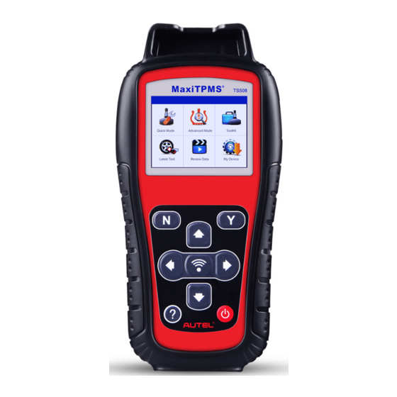
Tool Information Functional Description Figure 2-1 MaxiTPMS TS508 SENSOR SLOT – holds the MX-Sensor to be programmed. LCD DISPLAY – displays the menus and test screens. N BUTTON – cancels a selection (or action) from a menu or return to previous menu. -
Page 9: Specifications
this button to move up to previous screens for additional data. It is also used to view previous trouble code when viewing DTCs. LEFT SCROLL BUTTON – when scrolling through a screen of data or text, moves to previous character and views additional information on previous screens, if recorded data content covers more than one screen. -
Page 10: Accessories Included
Item Description Power 4.10 V Li-polymer battery Operating Temp. -20° C to 60° C (-4° F to 140° F) Storage Temp. -10° C to 45° C (14° F to 113° F) Dimensions 215 mm (8.46”) / 105 mm (4.13”) / 37 mm (1.46”) Weight 0.39 kg (0.86 lb.) Accessories Included... -
Page 11: Keyboard
– indicates the tool communication with the vehicle’s OBD II DLC is established or indicates the sensor information is read by OBD. Keyboard Use a mild nonabrasive detergent and a soft cotton cloth to clean the keypad and display. No solvents such as alcohol are allowed for device cleaning. Do not soak the keypad as the keypad is not waterproof. - Page 12 Connect the OBD II cable to the TPMS tool. Find DLC on vehicle. TIPS A plastic DLC cover may be found for some vehicles and you need to remove it before plugging the OBD II cable. Connect OBD II cable to the vehicle’s DLC. Power up the TPMS tool by pressing the Power button, and wait for the Main Menu to display.
-
Page 13: Tpms Quick Mode
TPMS Quick Mode Perform basic TPMS functions through the Quick service mode. Scan Sensor, Program Sensor, Relearn Procedure and Sensor Information. = Confirm Select test vehicle to start a TPMS service session. Vehicle Identification = Confirm... - Page 14 Select by Model = Confirm Select by Year For vehicles using indirect TPMS: = Confirm Follow the instructions displayed to perform Relearn for indirect TPMS.
-
Page 15: Scan Sensor
For vehicles using direct TPMS: = Confirm Functions provided in Quick Mode: Scan Sensor, Program Sensor, Relearn Procedure, and Sensor Information. Scan Sensor Hold the tool close to the sensor or close to the tire sidewall right above the sensor. For first time use:... - Page 16 Press Y or Trigger to trigger the sensor. The device is receiving data from the sensor. Trigger Successful. The ID, pressure, temperature and voltage of the sensor display on screen.
-
Page 17: Program Sensor
Failed. Press Y or Trigger to try again. Program Sensor Copy by Activation This function is used to activate or trigger the original sensor and retrieve the ID of the sensor, and then write the original sensor ID into the new MX-Sensor. - Page 18 Press to select Copy by Activation. Place the tool near the sensor to be copied. If the sensor is still attached to the wheel, hold the tool close to the tire sidewall right above the sensor. = Confirm Press Y or Trigger to trigger the sensor.
- Page 19 Trigger failed. Press Y or Trigger to try again. Place a new MX-Sensor in the sensor slot or hold the top of the tool close to the sensor to program. Sensor Programming The programming function automatically begins.
- Page 20 Try to program sensor again. The number in the brackets indicates the fault code, it can be used for Autel techincians to quickly identify the fault. No sensor detected. Ensure the unit software is up to date.
- Page 21 Multiple sensor detected. Ensure that only one sensor is close to the tool. Copy by Manual Input This function is used to manually input the original sensor ID and program it to new MX-Sensor. = Confirm Press Trigger to select the numbers, press N to exit and once a number is selected, the N button can be used to delete the entered number.
- Page 22 = Exit = Confirm and Program Sensor Programming The programming function automatically begins. Once programmed, sensor and tire data will display.
- Page 23 A failure message displays if the sensor fails to program. Press any key to continue. Ensure a MX-Sensor with the correct frequency is used. Try to program sensor again. No sensor detected. Ensure the unit software is up to date. Multiple sensor detected.
- Page 24 Place 1-16 MX-Sensor(s) close to the top of the tool. The tool will automatically detect the sensors near the tool. = Cancel = Continue...
-
Page 25: Relearn Procedure
Once the sensors are successfully programmed, the sensor IDs and the PSNs (Product Serial Number) will display on the tool. Relearn Procedure = Confirm Read the Relearn Procedure carefully to complete the operation. -
Page 26: Sensor Information
Sensor Information = Confirm MX-Sensor Information Place a MX-Sensor near the top of the tool and then press Y. = Confirm... - Page 27 NOTE Area Code is the code used to identify the area of your tool for Autel Support when you file a problem report. OE Sensor Information = Confirm The tool will automatically display the information of the OE sensor mounted on the test...
-
Page 28: Tpms Advanced Mode
TPMS Advanced Mode The Advanced service mode performs additional TPMS functions: TPMS Diagnose, Program Sensor, Position Relearn and Information (OE and MX- Sensor data and vehicle OBDII port location diagram). Vehicle Identification = Confirm Select by Model = Confirm... - Page 29 Select by Year For vehicles using indirect TPMS: = Confirm Follow the Relearn procedure displayed for vehicles with indirect TPMS. For vehicles using direct TPMS: = Confirm...
-
Page 30: Tpms Diagnose
Functions provided in Advanced Mode: TPMS Diagnose, Program Sensor, Position Relearn and Information. For some vehicle, a fifth option: Tire Type/Pressure Section is available. TPMS Diagnose This function is used to check TPMS and sensor status. = Confirm The TPMS Diagnose Guide will display if sensor activation is not performed before. - Page 31 If sensor activation is performed and there is data saved in the tool, a Clear Previous Data message displays. Press No to turn to the existing sensor activation menu and reactivate one sensor, then the tool will prompt you to connect OBD cable for ECU diagnosis, or press Yes to clear the previous data and reactivate the sensors.
- Page 32 Sensor activation failed. Sensor activation successful. Sensor ID displays on the left side of the bottom bar and the temperature displays on the right side of the bottom bar. D icon indicates that a duplicate sensor ID has been read.
- Page 33 All sensors have been triggered. Display advances to connect OBD cable for diagnosis even if not all sensors have been successful activated. Follow the onscreen instructions to connect the tool with the test vehicle via OBD II cable. Turn on the ignition.
- Page 34 A message will display if IDs and DTCs have been read successfully. Green signal and OBDII icons: the ECU ID matches Sensor ID. Red signal and OBDII icons: the ECU ID does not match Sensor ID. Red battery icon: low sensor battery Amber TPMS icon: DTC(s) present in the ECU.
- Page 35 Pressure, temperature and battery level display on the second page. Press N to exit. Use Up and Down Arrow button to select the TPMS icon in the center of the graphed vehicle and press Y to view the DTCs. = Back = Erase DTC = Save...
-
Page 36: Program Sensor
Press OK to continue. Erase DTCs Success. The tool will automatically re-check the If no DTC(s) is present in the ECU, ECU to ensure all DTCs have been the middle TPMS icon displays gray and a “No DTCs” message displays deleted. - Page 37 There are four ways to program MX-Sensors: Copy by OBD, Copy by Activation, Copy by Manual Input and Auto Create 1-16 Sensors. Copy by OBD Copy the sensor ID from ECU into a MX-Sensor. Press Y to confirm selection. If no TPMS diagnosis is performed before, the tool will prompt the user to connect OBD...
- Page 38 Follow the onscreen instructions to connect the tool with the test vehicle via the OBD II cable. Press Y to continue, or press N to exit. The tool will automatically read data from the ECU. The sensor IDs saved in the ECU display on the screen.
- Page 39 No sensor detected. Press any button to continue. Multiple sensors detected. Place one sensor close to tool, and press any key to continue. One sensor is detected. The programming function automatically proceeds.
- Page 40 Programming successful. Sensor ID, PSN, Pressure, Temperature, Frequency and Voltage are displayed on the screen. Programming Failed. Press any key to continue. By using Copy by OBD, the sensor ID that is retrieved from TPMS ECU is programmed to the new MX-Sensor. There is no need to perform the Relearn function to write the ID into the ECU when the new programmed sensor has been put in the same position.
- Page 41 Select Copy by Activation from programming list. Activate or Trigger sensor to be copied. Trigger successful. Original sensor ID displays on screen. Press Y to program the original sensor ID to MX-Sensor. Trigger failed. Press Y or Trigger to try again.
- Page 42 Place a new MX-Sensor near the top of the tool to program. No sensor detected. Press any button to continue. Multiple sensor detected. Place one sensor close to top of tool, and press any button to continue.
- Page 43 One sensor is detected. The programming function automatically proceeds. Programming succeeded. Sensor ID, PSN, Pressure, Temperature, Frequency and Voltage are displayed on the screen. Programming Failed. Press any key to continue. By using Copy by Activation, the sensor ID that is retrieved from activated sensor is programmed to the new MX-Sensor.
- Page 44 Copy by Manual Input This function is used to manually input the original sensor ID and program it to a new MX-Sensor. = Confirm Press Trigger to select the numbers, press N to exit and once a number is selected, the N button can be used to delete the entered number.
- Page 45 No sensor detected. Press any button to continue. Multiple sensors detected. Place one sensor close to top of tool, and press any button to continue. One sensor is detected. The programming function automatically proceeds.
- Page 46 Programming successful. Sensor ID, PSN, Pressure, Temperature, Frequency and Voltage are displayed on the screen. Programming Failed. Press any key to continue. The Copy by Input programming method uses the ID of the original sensor that is already stored within the TPMS ECU and therefore does not require the sensor be relearned if the new programmed sensor has been put in the same wheel location.
- Page 47 Place 1-16 MX-Sensor(s) close to the top of the tool. The tool will automatically detect the sensors near the tool. = Cancel = Continue...
-
Page 48: Position Relearn
Once the sensors are successfully programmed, the sensor IDs and the PSNs will display on the tool. Position Relearn Generally speaking, there are three ways for position relearn: Stationary Relearn, Automatic Relearn and OBD Relearn. Stationary Relearn Stationary Relearn requires the vehicle be placed in the “Learn Mode”. = Confirm... - Page 49 Read the Relearn Procedure carefully and press Y to continue. Follow the onscreen instructions to activate all the sensors mounted on the vehicle. Note: all the sensors should be successfully activated without any duplicated IDs. Once all sensors are successfully activated, then follow the Relearn Procedure to perform Stationary Relearn.
- Page 50 = Confirm Follow the Relearn Procedure to perform Automatic Relearn. OBD Relearn The OBD Relearn function allows the TS508 to directly write the TPMS sensor IDs to the TPMS module. To perform Relearn, activate sensors on FL, FR, RR and RL wheels. If there is sensor triggered, the tool will ask whether to clear the saved data, press N to use the saved data...
- Page 51 Read the Relearn Procedure carefully and press Y to continue. If no sensor activation is not performed before, follow the onscreen instructions to activate all the sensors mounted on the vehicle. Note: all the sensors should be successfully activated without any duplicated IDs.
- Page 52 Follow the onscreen instructions to connect the tool and vehicle via OBD cable and turn the ignition on. Press Y to continue. The tool is writing sensor ID to ECU, please wait. OBD Relearn Failed. Press any key to continue.
- Page 53 OBD Relearn Successful. The sensor IDs have been written to the ECU and the tool will automatically erase the DTCs present in the ECU. When all DTCs have been deleted, the TPMS icon displays gray. Press any key to continue.
-
Page 54: Information
Information MX-Sensor Information Place a MX-Sensor near the top of the tool and press Y to continue. - Page 55 OE Sensor Information = Confirm The tool will display the information of the OE sensor for the selected vehicle. OBD Location...
- Page 56 Tire Type/Pressure Selection If all TPMS faults are cleared and the four tires are inflated to the reference pressure listed on the placard, but the TPMS MIL is still on, you may need to use this function to select your tire type and set the right tire pressure value. Read Tire Type/Pressure Select Read Tire Type/Pressure and press Y to read the tire type and pressure of the test vehicle.
- Page 57 Write Tire Type/Pressure Select the item you want to change and press Trigger to enter the edit menu (Take Front Tire Type as an example). Use the UP/DOWN button to select the correct tire type and press Y to confirm and exit. Move to the next item: Front Tire Pressure on Placard, and press the Trigger button to edit.
- Page 58 Use the UP/DOWN button to select the correct tire pressure on placard and press Y to confirm and turn to the previous menu. After all the changes are completed, press Y to confirm and exit, or press N to exit without saving the changes.
-
Page 59: Miscellaneous
Miscellaneous ToolKit Test strength of remoteless key fob signal or unlock ECU for Toyota vehicles. Select ToolKit from the Main Menu and press the Y button to confirm. Figure 5-1 Sample ToolKit Selection Screen The screen displays as below, select RKE & RF Monitor and press Y to confirm test strength of remoteless key fob. -
Page 60: Latest Test
fob to test. If the button works and the key fob is sending a signal, the tool will beep and the screen displays as below. If the button does not work, the tool will do nothing. To make sure each button is working properly, please test each button in turn. - Page 61 If you already have an Autel account, Sign In with your account ID and password. If you are a new member to Autel, click on the Create Autel ID button on the left side to create an ID. Enter the required information in the input fields, and click the Get Verification Code button to get the verification code for email validation.
- Page 62 MaxiTPMS TS508 > Downloads, or from www.maxitpms.com > Support > Freshdesk > Firmware & Downloads > MaxiTPMS TS508, and install it to your Windows-based computer. Run the Maxi PC Suite on the computer. Select Update on the My Device Menu to enter Update Mode.
- Page 63 In the Update Available window, select the appropriate files to install. Figure 5-6 Sample Update Window View or Delete Programs To view the list of installed programs or to delete an installed program, please follow these steps: Click on the Installed tag entry and the list of installed programs displays. Select the program(s) that you would delete.
- Page 64 action. The deleted program will be added to the end of program list on the Update Available page, if you wish to reinstall programs. Setting The tool allows you to make the following adjustments and settings. Market: Selects the operating region of the tool. Language: Selects the operating language of the tool.
- Page 65 Market TIPS The default market selection depends on the area the tool is sold. From System Setup screen, use the UP/DOWN scroll button to select Market, and press the Y button. Use the LEFT/RIGHT scroll button to select the desired market or tool operating region and press the Y button to save your selection and return to previous menu.
- Page 66 Figure 5-10 Sample Language Selection Screen ID Format From System Setup screen, use the UP/DOWN scroll button to select ID Format, and press the Y button. From ID Format screen, use the LEFT/RIGHT scroll button to select the desired ID format. Figure 5-11 Sample ID Format Screen Press the Y button to save your settings and return to previous menu, or press the N button to exit without change.
- Page 67 Figure 5-12 Sample Pressure Unit Screen Press the Y button to save your settings and return to previous menu, or press the N button to exit without change. Temperature Unit From System Setup screen, use the UP/DOWN scroll button to select Temperature Unit, and press the Y button.
- Page 68 Distance Unit, and press the Y button. From Distance Unit screen, use the LEFT/RIGHT scroll button to select the desired unit of distance: km or mile. Figure 5-14 Sample Distance Unit Screen Press the Y button to save your settings and return to previous menu, or press the N button to exit without change.
- Page 69 change. Power-off From System Setup screen, use the UP/DOWN scroll button to select Power-off, and press the Y button. Press UP/DOWN scroll button to increase or decrease the amount of time of inactivity before the tool automatically powers off. Press the Y button to confirm your change or the N button to exit without change.
-
Page 70: Print
Figure 5-17 Sample Date and Time Screen About This function allows viewing of tool data such as serial number and software version number of the tool. From System Setup screen, use the UP/DOWN scroll button to select About, and press the Y button; wait for the About screen to display. View tool information on screen. - Page 71 MaxiTPMS TS508 > Downloads, or from www.maxitpms.com > Support > Freshdesk > Firmware & Downloads > MaxiTPMS TS508, and install it to your Windows-based computer. Connect the tool to the computer with the supplied USB cable. Run Autel Printer software on computer.
-
Page 72: Product Troubleshooting
Exit – quit the operation. Product Troubleshooting This part describes problems that you may encounter while using the TPMS tool. Vehicle Linking Error A communication error occurs if the TPMS tool fails to communicate with the vehicle’s ECU (Electronic Control Unit) when running the diagnostic function. You need to do the following to check up: ... -
Page 73: Compliance Information
Compliance Information FCC COMPLIANCE FCC ID: WQ82016-TS408 This device complies with Industry Canada’s licence-exempt RSSs. Operation is subject to the following two conditions: This device may not cause harmful interference. This device must accept any interference received, including interference that may cause undesired operation. Cet appareil est conforme aux CNR exempts de licence d’Industrie Canada. - Page 74 – Reorient or relocate the receiving antenna. – Increase the separation between the equipment and receiver. – Connect the equipment into an outlet on a circuit different from that to which the receiver is connected. – Consult the dealer or an experienced radio/TV technician for help. Changes or modifications not expressly approved by the party responsible for compliance could void the user’s authority to operate the equipment.
-
Page 75: Warranty And Service
Warranty and Service Limited One Year Warranty Autel Intelligent Technology Corp., Ltd. (the Company) warrants to the original retail purchaser of this MaxiTPMS Diagnostic Device that should this product or any part thereof during normal usage and under normal conditions... -
Page 76: Service And Support
Service and Support If you have any questions regarding the product, please contact one of our offices in your region. AUTEL NORTH AMERICA Phone: 855-AUTEL-US (855-288-3587) Monday-Friday 9am-6pm EST Website: www.autel.com, www.maxitpms.com Email: ussupport@autel.com... - Page 77 Address: Office 103, Building 3845, International Business Park, Veracruz, Panamá Pací fico, Panamá AUTEL AUSTRALIA Phone: 03 9480 2978 / +61 476293327 Website: www.autel.com.au, www.maxitpms.com Email: sales@autel.com.au Address: 155 Islington Street, Melbourne, Collingwood, VIC For technical assistance in other markets, please contact your local...
Need help?
Do you have a question about the MaxiTPMS TS508 and is the answer not in the manual?
Questions and answers