Table of Contents
Advertisement
Advertisement
Table of Contents

Summary of Contents for PoKeys PoKeys57CNC
- Page 1 PoKeys57CNC User’s manual Version: 23/3/2017...
- Page 2 16. The licensee agrees to allow access to this software only to persons who have been informed of and agree to abide by these conditions. 17. Trademarks: Windows is a registered trademark of Microsoft Corporation. PoKeys, PoKeys55, PoKeys56U, PoKeys56E, PoKeys57U, PoScope, PoLabs and others are internationally registered trademarks.
-
Page 3: Table Of Contents
Contents Introduction ............................. 7 Features ............................8 Device hardware description......................9 3.1. PoKeys57CNC connector pinout .................... 11 Pin types ............................11 Power supply ..........................11 SSR (Solid State Relay) connector ....................12 Relays connector ........................... 12 Galvanically isolated I/Os ......................12 LCD connector .......................... - Page 4 Using USB ..........................24 6.2. Using Ethernet - direct connection between PoKeys57CNC and computer ......24 6.3. Using Ethernet - PoKeys57CNC connected to a network with DHCP server ......25 6.1. Using USB and Ethernet ......................25 6.2. Motor drivers and peripherals installation ................25 PoKeys configuration options ......................
- Page 5 Device recovery mode ........................78 Frequently asked questions ......................79 Errata information ........................80 PoKeys device resets when external power supply is applied or removed ........80 External pull-up resistor needed on the probing input ..............80 Grant of license ......................... 81...
- Page 6 PoKeys user manual www.poscope.com...
-
Page 7: Introduction
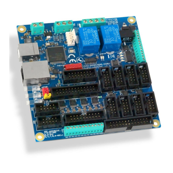
The device is highly adjustable and as such requires no complex knowledge on device programming. PoKeys57CNC is a blend between general purpose PoKeys device and motor controller. The device is targeted primarily for controlling up to 8 STEP/DIR signal driven motors (stepper motors, servo drives, etc.) in various applications with the addition of powerful PoKeys device features. -
Page 8: Features
PoKeys user manual 2. Features Compatible with USB 1.1/2.0 HID standard, standard English USB keyboard simulation (with triggering support for up/down keys), standard USB joystick simulation (6 axes, 32 buttons with triggering support), Ethernet 10/100 with DHCP client or fixed IP support,... -
Page 9: Device Hardware Description
PoKeys user manual 3. Device hardware description www.poscope.com... - Page 10 PoKeys user manual www.poscope.com...
-
Page 11: Pokeys57Cnc Connector Pinout
Positive power supply 6-26V (marked with +) Supply input Negative power supply (ground) PoKeys57CNC requires external 6-26V power supply to be connected to the board in order for the device to operate correctly (device may not operate according to the specifications if the external power supply is not present). -
Page 12: Ssr (Solid State Relay) Connector
Function Ground +5V power supply for LCD DIO33 LCD contrast voltage, also used as PoKeys pin 18 with PWM and reset pin (see Device recovery mode for more details) DIO33 LCD RS signal, also used as PoKeys pin 29 DIO33... -
Page 13: Pendant Connector
LCD D7 signal, also used as PoKeys pin 23 LED+ +5 V power supply for LCD backlight with 4,7 Ω resistor in series LED- Open-collector output (max. 100 mA), also used as PoKeys pin 22 with Pendant connector Pin Type Label... - Page 14 PoKeys user manual a) E-stop switch is connected to dedicated 4-pin E-stop connector between pins 2 and 3. Jumper 'NeST' must be removed and inserted into the pendant connector between pins 4 and 6 b) E-stop switch is connected to pendant connector (between pins 4 and 6). Jumper 'NeST' must...
-
Page 15: Encoders Connector
Encoders connector Pin Type Label Function Axis enable signal (inverted) Ground DIO33 uFEA Ultra-fast encoder A-channel signal input, also used as PoKeys pin 8 Ground DIO33 uFEB Ultra-fast encoder B-channel signal input, also used as PoKeys pin 12 Ground DIO33 uFEI... -
Page 16: Motor Connectors 1-8
Function /AXEn Axis enable signal (inverted) Ground Direction signal Ground STEP Step signal Ground DI5P /ERRORin Error input signal (from stepper driver to PoKeys) Ground +5V output to stepper driver Ground Axis switches connector Pin Type Label Function Ground Ground... -
Page 17: Lpt-Port) Io Connector
DB-25 (LPT-port) IO connector Warning: on PoKeys57CNC v1.1 the pinout is not compatible with the LPT-based stepper drivers since the physical pin numbering sequence in PoKeys57CNC v1.1 differs from that of a real DB-25 connector. Check the pinout diagrams above. -
Page 18: Pin Types And Specifications
PoKeys user manual 3.2. Pin types and specifications Type DI5P: Digital input with filtering Symbol Parameter Unit maximum voltage applied to DI5P pin DI5P,MAX applied voltage for LOW state DI5P,LOW applied voltage for HIGH state DI5P,HIGH Type DO5: 5 V digital output... -
Page 19: Type Dio33: 3,3 V Digital Input Or Output
PoKeys user manual Type DIO33: 3,3 V digital input or output Digital pin directly connected to MCU. Symbol Parameter Unit pull-up current -100 µA >= 3.3V Pin used as digital output maximum current supplied by DO33 pin DO33,MAX voltage of LOW state (no current) -
Page 20: Type Ocssr: Open-Collector Output For Ssr (Solid State Relay)
PoKeys user manual Type OCSSR: open-collector output for SSR (Solid State Relay) Symbol Parameter Unit maximum current sunk by OCSSR pin OCSSR,MAX maximum voltage applied to OCSSR pin OCSSR,MAX Type REL: relay output Symbol Parameter Unit maximum current switching at 28 VDC... -
Page 21: Type An33F: 3.3 V Analog Input With Low-Pass Filter
PoKeys user manual Type AN33F: 3.3 V analog input with low-pass filter Symbol Parameter Unit analog input voltage on ADC related pins -0.5 cut-off frequency of the analog low-pass filter 3.3. Status LEDs o TBD www.poscope.com... -
Page 22: Requirements
4. Requirements 6-26 V power supply with 2.5 W or more, one available USB 1.1 or USB 2.0 port, Ethernet connection between host computer and PoKeys57CNC device, USB HID device driver enabled operating system (Windows 98 SE/ME/2000/XP/Vista, Linux, Mac OS), included software requires Windows XP/Vista/7/8/8.1 with .NET framework 3.5 installed. -
Page 23: Technical Specifications
PoKeys user manual 5. Technical specifications 5.1. PoKeys57CNC dimensions Measurements are in mm. 5.2. Environment specifications Parameter Unit Power supply range Operating temperature °C Storage temperature °C Humidity 95 (non-condensing) % RH www.poscope.com... -
Page 24: Installation
6.2. Using Ethernet - direct connection between PoKeys57CNC and computer Network firewalls must allow all traffic on TCP/UDP port 20055 between PoKeys57CNC device and PoKeys-related software running on a computer. Step 1: Locate ethernet ports on your computer (1) and PoKeys57CNC board (2) and connect them with RJ-45 cable (standard network cable). -
Page 25: Using Ethernet - Pokeys57Cnc Connected To A Network With Dhcp Server
Step 3: Install PoKeys software 6.1. Using USB and Ethernet PoKeys57CNC device can also be connected to computer by using both the USB and Ethernet connection. In this case, applications will detect two instances of PoKeys57CNC devices and USB connection will be selected by default by third-party applications. -
Page 26: Pokeys Configuration Options
Although primarily targetted for CNC applications, PoKeys57CNC shares the same virtual USB keyboard and joystick capability of PoKeys USB series of devices. Digital pins can be mapped to virtual keyboard keys or virtual joystick buttons. On activation, PoKeys device sends a USB message with the key code and modifier associated with this pin. - Page 27 Digital input set up for direct key mapping acts like a keyboard key. When there is a high state on pin (on low state when using inverted option), PoKeys device sends a key associated with this pin. Select a keyboard key from drop-down box and check appropriate key modifiers (Shift, Ctrl, …).
-
Page 28: Digital Counters
7.2. Digital counters Selected pins of the PoKeys device can be setup to count the number of signal transitions on those pins. Pin digital counter can be setup to be incremented/decremented on rising, falling or rising and falling edges of the input signal. -
Page 29: Encoders
PoKeys user manual 7.3. Encoders PoKeys devices can handle decoding of up to 26 pairs of quadrature encoder signals. A and B signals of 25 'normal' encoders can be connected to any digital input and are intended for hand-driven rotational encoder switches with the quadrature signal frequencies up to 1 kHz. -
Page 30: Pokeys Configuration Software Usage
PoKeys user manual PoKeys configuration software usage To enable encoder input on the selected pin, define the pin as digital input, switch to ‘Encoders/Counters’ tab, select encoder index with numerical up-down selector and select appropriate encoder channel. The last step is to check the box ‘Encoder’. - Page 31 PoKeys user manual Figure 4: Encoders' RAW values www.poscope.com...
-
Page 32: Pulse Engine
PoKeys user manual 7.4. Pulse engine PoKeys57CNC is a hybrid device between a USB PoKeys, Ethernet PoKeys nad PoKeysCNCaddon. As such, it contains an external pulse generator on-board, which is capable of driving of up to 8 axes controlled by STEP/DIR signals with maximum pulse frequency of 125 kHz. -
Page 33: Pulse Engine Status/Control Dialog Parts
STOP mode. b. ERR: error mode - if PoKeys detects any event that results in error (emergency stop, limit stop, etc.), this mode will automatically be activated. As STOP mode, the transition is instantaneous c. -
Page 34: Axis Configuration Panel
6. Motion configuration: axis direction can be inverted here. Optionally, internal motion controller can be activated, allowing PoKeys device to produce the motion signals based on position or speed reference setup. The ‘Mask enable’ option is for testing purposes and enables third-party software to enable individual axes independently. -
Page 35: Homing Algorithm Configuration
Fast encoders index inputs 1, 2, 3 (pins 9, 10 and 11 on PoKeys57CNC and 9, 11 and 27 for other PoKeys devices) are used for axes 1, 2, 3, while ultra fast encoder index input is used for axis 4. -
Page 36: Common Homing Algorithm Configurations
PoKeys user manual Common homing algorithm configurations Although the homing algorithm is configurable, there are some standard configurations that fit most CNC machine configurations: 1. Standard homing configuration 2. Homing without reverse 3. Homing with encoder index - standard 4. Homing with encoder index - without reverse... -
Page 37: Limit And Home Switch Filters
If PoStep60-256 drivers are connected with PoKeys57CNC device using PoExtension2 bus, configuration (step mode, temperature limit, motor current settings) of the drivers can be done via PoKeys57CNC device. Status of the drivers (temperature, voltage, input states, faults) can also be displayed. -
Page 38: Connecting Postep Drivers To Pokeys57Cnc
PoKeys user manual Automatic refresh of PoStep status can be enabled by configuring the auto-refresh options. Select the values to refresh and click on 'Configure'. PoKeys will periodically scan through PoStep devices and retrieve their statuses. Connecting PoStep drivers to PoKeys57CNC Connect PoStep drivers (PoStep60-256) in parallel with PoKeys57CNC device using PoExtension2 bus. - Page 39 PoKeys user manual Figure 12: I2C address configuration in PoStep configuration tool www.poscope.com...
-
Page 40: Matrix Keyboard
On all devices, the status of key presses of the matrix keyboard can be read using the PoKeys library commands without the need to setup the mapping described above. - Page 41 PoKeys user manual Figure 15: Assigning row and column pins Matrix keyboard column selection Each free digital input pin can be assigned as matrix keyboard column input. Make sure the selected pin is configured as digital input, then check the ‘Matrix keyboard’ option for the pin and select the appropriate column letter from the list.
-
Page 42: Analog Inputs
3.3 �� where U(k) (in Volts) is a voltage present on the selected analog input pin. PoKeys configuration software usage To open analog inputs dialog, go to Peripherals menu and select ‘Analog inputs and outputs’. Dialog below appears. To enable display of analog input channel, check the appropriate check box. It is enabled only when the input is set up as analog input. -
Page 43: Joystick Mapping
Figure 17: Analog inputs and outputs dialog 7.7. Joystick mapping Each axis of the PoKeys virtual joystick can be assigned an analog input source. In addition, analog to digital mapping option can be enabled, which allows user to connect an analog joystick to a PoKeys devices and simulate key presses for each direction of the joystick. -
Page 44: Pwm Outputs
Figure 18: Joystick mapping settings 7.8. PWM outputs PoKeys57CNC device supports PWM output function on 4 pins (pins 18, 20, 21 and 22). Different duty cycles can be assigned to each PWM output however, all outputs share the same PWM period. PWM outputs can be easily amplified using an external transistor and used for control of loads with www.poscope.com... -
Page 45: Pokeys Configuration Software Usage
- pins with such function embedded are marked as OC (open-collector) in the pinout diagram. PoKeys PWM outputs can also be used to drive various R/C servo motors that accept PWM signal with 50 Hz frequency (20 ms PWM period) and duty cycles between 5 and 10 % (1 to 2 ms). -
Page 46: Lcd
Usually these displays come in various sizes - 1/2/4 line with 8/16/20 characters and colors (black letters on green background, white letters on blue background ...). PoKeys57CNC device has a dedicated connector for such LCD displays - see the pinout section of the manual for connector pinout description. - Page 47 Button 'Clear LCD' clears LCD display and moves cursor to home position. LCD module is initialized automatically by PoKeys device on device startup if ‘Enable LCD support’ option is enabled. User can also set entry mode settings of LCD module. Cursor can be set-up to move either right (normally) or left after each character displayed.
- Page 48 PoKeys user manual LCD custom character editor Produced code unsigned char uCustomChar[8] = { 0x10, 0x1C, 0x04, 0x04, 0x04, 0x04, 0x07, 0x01, Move cursor This section enabled user to move cursor to any position on the screen works only in ‘unbuffered’...
-
Page 49: Poextbus
PoKeys user manual 7.10. PoExtBus PoExtBus bus support enables user to add additional ten 8-bit shift registers to add up to 80 additional digital outputs to PoKeys device. Figure 23: PoExtBus outputs chaining PoKeys configuration software usage To set-up and test PoExtBus, open 'Peripherals' > PoExtBus...'. The dialog below (Figure 24) appears. -
Page 50: Ponet
PoExtBus devices should be connected in series after the PoNET devices, as described below PoNET devices must be connected in parallel to each other PoExtBus devices must be connected in series There should be no PoExtBus device between PoKeys device and PoNET devices PoExtBus PoExtBus device... -
Page 51: Adding New Devices
PoKeys user manual Adding new devices After connecting new PoNET device, go to ‘Peripherals > PoNET...’. The following dialog will appear Figure 25: PoNET settings dialog with an unconfigured device In order to register new device, double click on the 'Unconfigured device' icon. In the next 10 seconds press any key on the device that is about to be added. -
Page 52: Ponet Kb48Cnc Keyboard
PoKeys user manual PoNET kb48CNC keyboard The device can be virually mapped to PoKeys matrix keyboard. Third party software can set the status of LEDs under the keys, read the light sensor that measure the amount of light in the environment and set the intensity of the LEDs. -
Page 53: Failsafe Settings
PoKeys user manual 7.12. Failsafe settings PoKeys devices support the configuration of the failsafe state for the digital outputs, PWM outputs, PoExtBus devices and PoKeys Pulse engine. When the communication with the device is interrupted for longer than a period defined in the failsafe configuration, peripherals listed above enter the failsafe mode, which can be setup in ‘Failsafe settings’... -
Page 54: Peripheral Communication Protocols
C, PoNET and PoExtBus use the same connector, PoExtBus, PoNET and I C functions are automatically switched by the PoKeys device. Marking the pin closer to the edge of the PoKeys57CNC board as pin 1, the I C devices should be connected as follows:... -
Page 55: 1-Wire
PoKeys devices support communication with 1-Wire slave devices (without parasitic power supply), connected to the pin 55 with external pull-up resistor (of approximately 5 kΩ). Protocol can be tested via PoKeys configuration software. Click on Peripherals > 1-Wire bus test... The following dialog appears. -
Page 56: Easysensors
‘Send to device’ on main PoKeys configuration window must be clicked to do that). There are 4 types of sensors supported and each type of sensor can be added by clicking a corresponding button at the bottom of the dialog. -
Page 57: Scan For 1-Wire Sensors
PoKeys user manual Scan for 1-wire sensors The command opens the ‘Add 1-Wire sensor’ dialog that allows the user to select PoKeys pin, where the 1-Wire bus is connected to. By clicking ‘Scan’, PoKeys device scans the 1-Wire bus for devices. - Page 58 PoKeys user manual a) Using gain and offset: specify the gain and offset characteristics of the sensor. The gain specifies the number of sensor units per 1 V of analog voltage, while the offset specifies the sensor value of analog voltage input of zero.
-
Page 59: List Of Supported Sensors
DS18B20 (Maxim) temperature sensor for the temperature range of -55 °C to +125 °C with the resolution of 0.0625 °C. As each sensor has its own unique sequence ID, up to 10 sensors can be connected to PoKeys. DS18S20 (Maxim) temperature sensor... -
Page 60: Usb Interface Configuration
PoKeys user manual 7.15. USB interface configuration The operation of the USB PoKeys devices can be adjusted in the Device > USB interface', as shown on the figure below. Figure 37: Accessing USB interface options By adjusting these options, the user is given the possibility to configure how device reacts on the system start, change the communication interval and configure which interfaces are visible to the system. -
Page 61: Enabling/Disabling The Interfaces
PoKeys user manual Enabling/disabling the interfaces Each USB PoKeys device uses 4 USB interfaces (i.e. USB devices) and thus appears as 'USB Composite Device' in the Device manager. If not needed, some (or all) interfaces can be disabled. Note: if all communication interfaces are disabled, configuration of the device will no longer be possible. -
Page 62: Network Device Functionality
This connection timeout value can be set in the dialog, shown in Figure 38. Device discovery Unless PoKeys device is configured with a fixed IP address or static DHCP lease option is enabled on the router, user has no direct display of what IP the PoKeys device is configured or assigned with. -
Page 63: Default Network Settings
PoKeys user manual Default network settings DHCP: enabled Port: 20055 Security: Full access Connecting to device in other network When the device is not detected automatically (either there is a firewall blocking the UDP broadcast messages or the device is not in the same network as a computer), custom IP address of the device can be entered by clicking on the 'Network settings... -
Page 64: Security
Full lock: unauthorised users can not neither read or write to the device. A user password is required to unlock access. The security is set up in PoKeys configuration software – on the Device menu, click Set device security... The password can contain any character and can be up to 32 characters long. -
Page 65: Web Interface (Dashboard)
PoKeys user manual Web interface (dashboard) Network PoKeys devices can be monitored through the simple web interface (that is already enabled by default). Figure 41: PoKeys device web interface The interface can be disabled or configured in dialog accessible via menu Device->Web interface configuration. - Page 66 Access rights: select users from the list that should have access to the selected item. Custom unit editing PoKeys device contains 20 custom units that allow the user to setup additional units if needed. Since the units are displayed on a dashboard in a web browser, HTML code for the unit can be entered, allowing different text formatting.
- Page 67 - a ‘User account’ dialog will pop up, allowing the changes to user name and password. By default, PoKeys contains a user named ‘Admin’ with password set to ‘root0’. Both the username and password of this user can also be changed.
-
Page 68: Modbus
ID>&State=<0/1/T>&u=<Username>&p=<Password> http://<IP address> /setS.html?Sensor=<Item ID>&State=<Value>&u=<Username>&p=<Password> The <Pin ID> is 1-based PoKeys pin index (same as indicated on the device), while <Item ID> is 0- based dashboard item index of the current user. Modbus PoKeys57CNC device supports slave (server) operation of Modbus TCP communication protocol. - Page 69 PoKeys user manual Registers Supported operations: 0x03: Read holding register 0x04: Read input register 0x06: Write single register 0x10: Write multiple registers Address (0-based) Access (R – Read, W – Write) Description Serial number device (PoKeys57 only) 10-16 Analog inputs...
- Page 70 PoKeys user manual Device 4 Device 3 Device 2 Device 1 where 15 14 13 12 11 10 Modbus word bit PoExtBus device bit mapping Device 10 Device 9 Figure 46: Modbus configuration www.poscope.com...
-
Page 71: Reporting Data To Network Server With Pokeys57Cnc Device
PoKeys user manual Reporting data to network server with PoKeys57CNC device PoKeys57CNC devices can automatically report sensor values to various network servers using the HTTP POST, HTTP PUT or text-only protocols. To use this reporting feature, user must specify reports type (RAW, UDP, Xively, Standard HTTP POST/PUT or custom), server IP, server port number and update rate. - Page 72 Web and to build their own applications based on that data. PoKeys57CNC devices feature a direct support for the Xively web service. To configure PoKeys device for Xively, follow these steps: 1. Sign-up for a free account at http://xively.com/ 2.
- Page 73 7. Click Send to device button. If you wish to save the settings to non-volatile memory, click ‘Send to device’ on main PoKeys screen. Go back to Device > Web interface settings to edit the dashboard items. Define entries as described in the ‘Web interface’...
- Page 74 Figure 48: Item configuration for the Xively service 9. Save the settings again by clicking 'Send to device' button. 10. Make sure the PoKeys device has properly configured network settings and that it is connected to the internet 11. After a update interval, check the status of the Xively updates in the Xively 'Develop' page...
- Page 75 HTTP type of 'text/plain' and preceded with the string 'MyData: '. The data should be transferred every 10 minutes. The settings are displayed in Figure 50. To setup PoKeys to use these settings, the following steps must be taken (enter text without ' quotes): 1.
- Page 76 PoKeys user manual Figure 50: Example of HTTP POST service setup www.poscope.com...
-
Page 77: Changing User Id Number
PoKeys user manual 7.17. Changing User ID number Users can freely assign their own User ID number that represents a specific PoKeys device (enables distinguishing between different PoKeys devices in case there is more than one connected to a single host PC). -
Page 78: Device Recovery Mode
1. Disconnect PoKeys57CNC device from USB and remove power supply 2. Locate LCD connector on the PoKeys57CNC device and short the pins 1 and 3 as shown below 3. Reconnect the PoKeys device to USB (or reconnect power) 4. Green status light should start flashing rapidly and PoKeys device will connect in recovery mode 5. -
Page 79: Frequently Asked Questions
Ethernet. Windows can not find drivers for PoKeys57CNC device The drivers should automatically be installed by PoKeys setup package. If this is not the case and Windows reports unknown device, install the drivers manually by instructing the Windows device setup wizard to look for drivers in PoKeys installation folder (C:\Program Files\PoLabs\PoKeys\ by default). -
Page 80: Errata Information
This section describes special limitations of the device. PoKeys device resets when external power supply is applied or removed If PoKeys device is connected to USB, the device resets when external power supply is either applied or removed. External pull-up resistor needed on the probing input On PoKeys57CNC v1.0, v1.1 and v1.2 hardware, external pull-up resistor is required for correct... -
Page 81: Grant Of License
We provide upgrades, free of charge, from our web site at www.poscope.com. We reserve the right to charge for updates or replacements sent out on physical media. Trademarks Windows is a registered trademark of Microsoft Corporation. PoKeys, PoKeys55, PoKeys56U, PoKeys56E, PoScope, PoLabs and others are internationally registered trademarks. support: www.poscope.com...
Need help?
Do you have a question about the PoKeys57CNC and is the answer not in the manual?
Questions and answers