Table of Contents
Advertisement
ITW Dynatec
An Illinois Tool Works Company
31 Volunteer Drive
Hendersonville, TN 37075 USA
Telephone 615.824.3634
FAX 615.264.5222
Adhesive Application Solutions · ISO 9001 Certified
ä
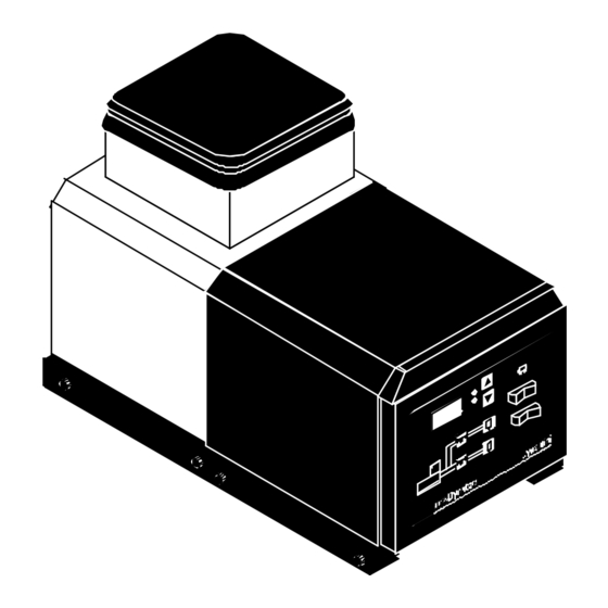
DYNAMINI
OPERATIONS AND SERVICE MANUAL
with Software Version 2.00
For an online copy of this manual, go to www.itwdynatec.com/manuals.htm
IMPORTANT ! - READ ALL INSTRUCTIONS BEFORE OPERATING THIS EQUIPMENT
It is the customer's responsibility to have all operators and service personnel read and understand
this information. Contact your ITW Dynatec customer service representative for additional copies.
NOTICE! Please be sure to include the serial number of your application system
each time you order replacement parts and/or supplies. This will enable us to
send you the correct items that you need.
ITW Dynatec GmbH
Industiestrasse 28
D-40822 Mettmann, Germany
Telephone 49.2104.915.0
FAX 49.210.2104.915.111
ITW Dynatec K.K.
Daiwashinagawa Bldg., 7-15 Konan, 3-Chome
Minata-Ku, Tokoyo 108 Japan
Telephone 81.3.3450.5901
FAX 81.3.3450.8405
ADHESIVE SUPPLY UNIT
ITW Dynatec Service Parts Direct Dial: 1-800-538-9540
ITW Dynatec Technical Service Direct Dial: 1-800-654-6711
OPERATIONS & SERVICE MANUAL
Manual 20 -25
Revised 1/05
Advertisement
Table of Contents
Troubleshooting

Summary of Contents for ITW Dynatec DYNAMINI
- Page 1 It is the customer’s responsibility to have all operators and service personnel read and understand this information. Contact your ITW Dynatec customer service representative for additional copies. NOTICE! Please be sure to include the serial number of your application system each time you order replacement parts and/or supplies.
- Page 2 Page ii ITW Dynatec c. 2004 Revised 1/05 DYNAMINI ASU Manual #20 -25 The Dynamini ASU is manufactured under one or more of the following PATENTS: United States: D388,800 5,613,451 5,632,918 5,645,743 5,683,578 5,719,378 5,806,720 Europe: 97309164.8-2206 ITW Dynatec An Illinois Tool Works Company...
-
Page 3: Table Of Contents
............Chapter 5 Programming of the Dynamini Controller Controller Keypad . - Page 4 ITW Dynatec c. 2004 Revised 1/05 DYNAMINI ASU Manual #20 -25 Hopper Filter Inspection and Cleaning ..........
- Page 5 Page 1-1 ITW Dynatec c. 2004 Revised 9/98 DYNAMINI ASU Manual #20-25 Chapter 1 SAFETY PRECAUTIONS All operators and service personnel must read All maintenance and service on this equip- and understand this manual before operating ment must be performed by trained techni- or servicing equipment.
- Page 6 Page 1-2 ITW Dynatec c. 2004 Revised 3/97 DYNAMINI ASU Manual 20-25 Eye Protection & Protective Clothing Wear safety glasses with side shields which conform to WARNING ANSI Z87.1 or EN166. EYE PROTECTION Failure to wear safety glasses could result in severe eye injury.
- Page 7 Page 1-3 ITW Dynatec c. 2004 Revised 9/98 DYNAMINI ASU Manual #20-25 Service Refer all servicing to qualified personnel only. Explosion/ Fire Hazard Never operate this unit in an explosive environment. of cleaning compounds vary according to their com- position, so consult with your supplier to determine the Use cleaning compounds recommended by ITW maximum heating temperatures and safety precautions.
- Page 8 Page 1-4 ITW Dynatec c. 2004 Revised 3/97 DYNAMINI ASU Manual 20-25 ITW Dynatec An Illinois Tool Works Company...
-
Page 9: Specifications And Dimensions
CHS = Hand Swirl Applicator STACKTITE SYSTEM OPTIONS: SB = Bead applicator SS = Swirl applicator EXAMPLE: N52GAS2-F = Dynamini 10 lb. hopper w/ 1.5cc gear pump, 240 VAC/ 1 phase and 100 mesh outlet filter. DYNAMINI Model Designation Matrix... -
Page 10: Specifications
Page 2 -2 ITW Dynatec c. 2004 Revised 1/05 DYNAMINI ASU Manual #20 -25 Specifications Environmental: Storage/ shipping temperature ...... - Page 11 Page 2 -3 ITW Dynatec c. 2004 Revised 1/05 DYNAMINI ASU Manual #20 -25 Pressurized Air: Air pressure supply .........
- Page 12 Page 2 -4 ITW Dynatec c. 2004 Revised 1/05 DYNAMINI ASU Manual #20 -25 DIMENSION mounting holes* MODEL 05 (mm) MODEL 05 (inches) 11.38 20.75 21.25 9.37 17.75 25.0 15.0 MODEL 10 (mm) MODEL 10 (inches) 11.38 20.75 21.25 9.37 25.75...
-
Page 13: Chapter 3 Installation & Start Up
INSTALLATION & START-UP Mounting the DYNAMINI ASU The DYNAMINI ASU can be mounted on most flat surfaces, on either an open or a solid frame (as shown below). The main electrical power and the serial communication connections come in from below the unit and connect under the keypad. -
Page 14: Installation
NOTE: Re-read Chapter 1 “Safety Precautions” before performing any installation procedures. All installation procedures must be performed by qualified, trained technicians. After the DYNAMINI ASU has been properly mounted, the following general sequence should be followed for installation: 1. Make sure that incoming line power to the ASU is turned OFF at a customer-provided circuit breaker. - Page 15 9. Refer to the Wattage Availability Chart on the next page to determine the hose and head power available for the various configurations of the Dynamini ASU. 10. The adhesive hoses are connected at the rear cover (see illustration on page 3-5). Make your electrical hose connections at the two numbered connects on the left side of the cover.
-
Page 16: Wattage Availability Chart
Page 3-4 ITW Dynatec c. 2004 Revised 1/05 DYNAMINI ASU Manual #20-25 Wattage Availability Chart Wattage Available for All Hoses and Heads ASU Voltage Max. System Hopper Gear Pump Piston Pump Gear Pump Wattage Wattage Motor Wattage 100-120 VAC 1800 @ 120VAC... - Page 17 Page 3-5 ITW Dynatec c. 2004 Revised 1/05 DYNAMINI ASU Manual 20-25 Air Pressure Regulator (clockwise increases) Pressurized Air In Air Flow 1/4 NPT female Air pressure gauge Pre-filter Coalescing filter Air Control/ Filter Unit Maintain adhesive level 13mm-100mm (1/2”- 4”) from top of hopper.
- Page 18 Allow adequate time (approximately 20-30 min.) for the adhesive to melt and the temperatures of the temperature zones to stabilize. Note: When the ASU leaves the ITW Dynatec factory, it is programmed with the following factory settings (unless special factory settings were requested): Hopper: 150°C (300°F)
-
Page 19: Storage And Disposal Of The Application System
ITW Dynatec c. 2004 Revised 1/05 DYNAMINI ASU Manual 20-25 Storage and Disposal of the DYNAMINI Application System Temporary Storage of the Unit 1. Flush the adhesive application system with flushing fluid (PN L15653), following the instructions detailed in chapter 6 of this manual. - Page 20 Page 3-8 ITW Dynatec c. 2004 Revised 1/05 DYNAMINI ASU Manual #20-25 ITW Dynatec An Illinois Tool Works Company Adhesive Application Solutions...
-
Page 21: Chapter 4 Dynamini Temperature Controller Set-Up
Printed Circuit Board (PCB) The Dynamini contains one pcb. It contains the central processing unit (CPU) of the microprocessor temperature control as well as providing control signals to, and monitoring signals from, the hopper, hoses and applicators. It features lighted LEDs to indicate that heater power is ON. The ASU’s fuses are located on this board. -
Page 22: Error Indication Messages
Page 4-2 ITW Dynatec c. 2004 Revised 1/05 DYNAMINI ASU Manual #20-25 Setpoint A programmable temperature that has been selected for hopper, hoses and applicators. Setpoint Limitation This is a universal maximum temperature for all zones (218°C [425°F]). The programmer cannot program a temperature setpoint higher than the setpoint limitation. -
Page 23: Settings For A Typical Operation
ITW Dynatec can set the controller’s system values to customer’s specs, if provided. If customer’s specs are not provided, the following values will be entered into the Dynamini tem- perture controller at the factory. They may be changed by reprogramming through the keypad. -
Page 24: Default Settings Of The Controller
Page 4-4 ITW Dynatec c. 2004 Revised 1/05 DYNAMINI ASU Manual #20-25 Default Settings of the Controller Default settings are the manufacturer’s preset values to which the system will return if the Dyna- mini tempearture control is subjected to an internal memory reset. While you can change your pro- grammed values to anything within the system’s limits, the default settings cannot be changed. -
Page 25: Programming
Page 5-1 ITW Dynatec c. 2004 Revised 1/05 DYNAMINI ASU Manual #20-25 Chapter 5 PROGRAMMING INSTRUCTIONS FOR DYNAMINI CONTROLLER Dynamini Keypad Scroll Keys: Temperature to increase value to reduce value Scale Pump Switch Temperature Display Main Power Switch Service Key... -
Page 26: Temperature Setpoints
Page 5-2 ITW Dynatec c. 2004 Revised 1/05 DYNAMINI ASU Manual #20-25 Programming temperature setpoints Choose a temperature zone. Scroll to “increase value” or ”reduce value”, in order to adjust the setpoint temperature. After two seconds the display will read the actual temperature. -
Page 27: Keypad Locking
Page 5-3 ITW Dynatec c. 2004 Revised 1/05 DYNAMINI ASU Manual #20-25 Keypad Locking It is possible to lock or unlock the controller in order to restrict programming changes. To change the code which is necessary to over-ride or unlock the keypad lock, see Service Functions. -
Page 28: Service Functions
Page 5-4 ITW Dynatec c. 2004 Revised 1/05 DYNAMINI ASU Manual #20-25 Service Functions After the basic programming of Temperature Setpoints is complete, the programmer proceeds to programming of the Service Functions, if desired. The Service Functions are a continuous loop of programming steps (”functions”) which the pro- grammer moves through by pressing the “Service”... - Page 29 Page 5-5 ITW Dynatec c. 2004 Revised 1/05 DYNAMINI ASU Manual #20-25 Service Functions , cont. Standby Programming “Standby” is a temperature value by which all temperature zones will lower when Standby mode is activated. For example, if your temperature setpoints are all 300 degrees, and you program a 100 degree Standby, then the Standby temperature of all zones will be 200 degrees.
- Page 30 Page 5-6 ITW Dynatec c. 2004 Revised 1/05 DYNAMINI ASU Manual #20-25 Service Functions, cont. To Set Tolerance (Hi & Low Temperature Limits) The Tolerance (high/ low alarm) setpoint is a range (+ and - - the zone’s temperature setpoint) be- tween which your ASU can safely operate.
- Page 31 Page 5-7 ITW Dynatec c. 2004 Revised 1/05 DYNAMINI ASU Manual #20-25 Service Functions, cont. To Set Temperature Scale The Temperature Scale may be set to display temperature either in degrees Celsius or Fahrenheit. Press the Service icon four times to set the Temperature Scale.
- Page 32 Page 5-8 ITW Dynatec c. 2004 Revised 1/05 DYNAMINI ASU Manual #20-25 Service Functions, cont. To Change Access Code (De-activate Keypad Locking) To change the Access Code, press the Service icon six times. You will see “C--1” to indicate you are in Access Code programming mode.
- Page 33 Page 5-9 ITW Dynatec c. 2004 Revised 1/05 DYNAMINI ASU Manual #20-25 Controller Features System Ready Indicator Light When not in programming mode, a flashing temperature scale light (LED) indicates that the ASU is not “Ready” for production. This LED will cease to flash when all temperature zones are within the pro- grammed temperature tolerance window.
- Page 34 Page 5-10 ITW Dynatec c. 2004 Revised 1/05 DYNAMINI ASU Manual #20-25 ITW Dynatec An Illinois Tool Works Company Adhesive Application Solutions...
-
Page 35: Chapter 6 Preventive Maintenence
Page 6-1 ITW Dynatec c. 2004 Revised 1/05 DYNAMINI ASU Manual #20-25 Chapter 6 PREVENTIVE MAINTENANCE Note: Re-read Chapter 1 “Safety Precautions” before performing any maintenance procedures. All maintenance procedures must be performed by qualified, trained technicians. General Cleaning Follow the manufacturer’s directions when using industrial cleaners on the enclosure. -
Page 36: Hopper Filter Inspection And Cleaning
Page 6-2 ITW Dynatec c. 2004 Revised 1/05 DYNAMINI ASU Manual #20-25 Hopper FIlter Inspection & Cleaning The hopper filter is a coarse screen located in the bottom of the hopper. It fits over the hopper’s drain hole and prevents any large debris from leaving the hopper. -
Page 37: Flushing The System
Page 6-3 ITW Dynatec c. 2004 Revised 1/05 DYNAMINI ASU Manual #20-25 Flushing the System Contaminated adhesive, accumulation of residue, or changing the adhesive formulation may require the system to be flushed. At least 6 liters (1.5 gallons) of flushing fluid is required (PN L15653). -
Page 38: Chapter 7 Troubleshooting
WARNING DANGER HOT SURFACE HIGH VOLTAGE Dynamini systems use electrical power that can be life threatening and hot-melt adhesives that can cause serious burns. Only qualified persons should perform service on the Dynamini sys- tem. Handling Printed Circuit Boards (PCBs) - Page 39 Page 7-2 ITW Dynatec c. 2004 Revised 1/05 DYNAMINI ASU Manual #20-25 Printed Circuit Board Notes: The PC board contains the controller’s software/ CPU chip and non-volatile memory. The green, temperature zone LEDs cycle on and off as each heater outputs.
-
Page 40: Overtemp Thermostat
Page 7-3 ITW Dynatec c. 2004 Revised 1/05 DYNAMINI ASU Manual #20-25 Overtemp Thermostat The overtemp thermostat is a safety back-up. If the hopper temperature exceeds 232°C (450°F), the thermostat causes a circuit breaker to open and power to the hopper and all hoses and heads will be cut off. -
Page 41: Resistance Tables
Page 7-4 ITW Dynatec c. 2004 Revised 1/05 DYNAMINI ASU Manual #20-25 Resistance Tables Temperature Resistance Hose Length Resistance in Ohms ° ° in Ohms Meters Feet 120V 240V 102-125 400-490 63-77 291-355 50-61 204-249 39-48 155-189 31-37 125-153 23.6-29 98-120 N.A. -
Page 42: Troubleshooting Guide
Page 7-5 ITW Dynatec c. 2004 Revised 1/05 DYNAMINI ASU Manual #20-25 Troubleshooting Guide Preliminary Checks: Verify the following before proceeding 1. The ASU is switched on. 2. The ASU is supplied with power. 3. The ASU is supplied with pneumatic air. - Page 43 Page 7-6 ITW Dynatec c. 2004 Revised 1/05 DYNAMINI ASU Manual #20-25 Problem Possible Cause Solution Hopper temperature is 1. Check hopper sensor. 1. Hopper sensor not fully higher than setpoint inserted. (overtemp). 2. Hopper sensor (X4) 2. Replace hopper sensor if resist- inoperative.
- Page 44 Page 7-7 ITW Dynatec c. 2004 Revised 1/05 DYNAMINI ASU Manual #20-25 Problem Possible Cause Solution Hopper does not heat, 1. Inoperative Control PCB. 1. Replace PCB. and LED is OFF. Hose (or Head) is not 1. Check plug connections.
- Page 45 Page 7-8 ITW Dynatec c. 2004 Revised 1/05 DYNAMINI ASU Manual #20-25 Problem Possible Cause Solution 1. Connect Hose (or Head) if need- 1. No Hose (or Head) is Display for Hose (or connected. ed. If not needed, ignore display.
-
Page 46: Pump Operation & Adjustable Pressure Relief
Page 7-9 ITW Dynatec c. 2004 Revised 1/05 DYNAMINI ASU Manual #20-25 Pump Operation & Adjustable Pressure Relief When the ASU’s hopper reaches setpoint, the controller places the hopper in “Ready” condition and power is supplied to the pump. An adjustable pressure relief valve is located on the output filter manifold. -
Page 47: Piston Pump Troubleshooting Guide
Page 7-10 ITW Dynatec c. 2004 Revised 1/05 DYNAMINI ASU Manual #20-25 Piston Pump Troubleshooting Guide WARNING HOT SURFACE & ADHESIVE Some of the procedures in the following Troubleshooting Guide require working near hot adhesive. Be sure to wear protective gloves, safety glasses and clothing and use proper tools for handling hot melt components. - Page 48 Page 7-11 ITW Dynatec c. 2004 Revised 1/05 DYNAMINI ASU Manual #20-25 Solution Problem Possible Cause 1. Verify that hopper has an adequate Pump Quick-Strokes in 1. No adhesive in hopper. level of hot melt adhesive. Both Directions 2. Check ready temperature to 2.
- Page 49 Page 7-12 ITW Dynatec c. 2004 Revised 1/05 DYNAMINI ASU Manual #20-25 Problem Possible Cause Solution Pump Motion on the 1. Outlet check valve is 1. Clean outlet check valve. Forward Stroke (shaft blocked closed. moving into pump) is very slow or stopped.
- Page 50 Page 7-13 ITW Dynatec c. 2004 Revised 1/05 DYNAMINI ASU Manual #20-25 Solution Problem Possible Cause 1.Remove seal from air motor and in Adhesive Leak at Pump 1. Pump seal out of proper spect it. Replace worn or damaged Shaft Seal position inside air motor seal.
-
Page 51: Gear Pump Troubleshooting Guide
Page 7-14 ITW Dynatec c. 2004 Revised 1/05 DYNAMINI ASU Manual #20-25 Gear Pump Troubleshooting Guide WARNING HOT SURFACE & ADHESIVE Some of the procedures in the following Troubleshooting Guide require working near hot adhesive. Be sure to wear protective gloves, safety glasses and clothing and use proper tools for handling hot melt components. - Page 52 Page 7-15 ITW Dynatec c. 2004 Revised 1/05 DYNAMINI ASU Manual #20-25 Problem Possible Cause Solution Pressure 5. The adjustable pressure 5. When fully closed (clockwise) and relief valve relief valve is opening. all applicators are off, adhesive pressure should be around 68 bar (1000 psi).
- Page 53 Page 7-16 ITW Dynatec c. 2004 Revised 1/05 DYNAMINI ASU Manual #20-25 ITW Dynatec An Illinois Tool Works Company...
-
Page 54: Chapter 8 Disassembly & Re-Assembly Procedures
Page 8-1 ITW Dynatec c. 2004 Revised 1/05 DYNAMINI ASU Manual #20-25 Chapter 8 DISASSEMBLY & RE-ASSEMBLY PROCEDURES Disassembly Procedures Note: Re-read Chapter 1 “Safety Precautions” before performing any disassembly procedures. All dissassembly procedures must be performed by qualified, trained technicians. -
Page 55: To Remove The Hopper Lid
Page 8-2 ITW Dynatec c. 2004 Revised 1/05 DYNAMINI ASU Manual #20-25 To Remove the Hopper Lid (See illustration on page 10-7) 1. Remove the four flat head screws which are located one on each side of the lid base. - Page 56 Page 8-3 ITW Dynatec c. 2004 Revised 1/05 DYNAMINI ASU Manual #20-25 To Access the Electrical Components (See also illustrations on pages 10-3 & 8-2) Control (Keypad) Board Remove the pump and electronics cover. Main On/ Off Switch Replacement: Note: there are two main switches (pump and ASU).
- Page 57 Page 8-4 ITW Dynatec c. 2004 Revised 1/05 DYNAMINI ASU Manual #20-25 Printed Circuit Board Replacement: Reference the manual section entitled “Handling Printed Circuit Boards” on page 7-1 before pro- ceeding. 1. Disconnect the ground spade on the pcb’s mounting bracket.
- Page 58 HIGH PRESSURE BEFORE PERFORMING ANY PUMP REPAIR, YOU MUST PURGE ALL ADHESIVE AND PRESSURE FROM THE DYNAMINI SYSTEM. Position a heat-resistant container under the filter manifold’s purge drain. Carefully loosen the purge screw located in the port of the outlet filter manifold and allow adhesive and pressure to escape.
-
Page 59: Note On Cast-In Heaters
Page 8-6 ITW Dynatec c. 2004 Revised 1/05 DYNAMINI ASU Manual #20-25 Gear Pump and Motor Removal: Gear Pump Disconnect from terminal 1. Disconnect the motor’s electrical cable rail from the ASU by unplugging it at the circuit Motor bracket... - Page 60 Page 8-7 ITW Dynatec c. 2004 Revised 1/05 DYNAMINI ASU Manual #20-25 Re-Assembly Procedures Unless noted, the ASU’s re-assembly is simply the reverse sequence of the disassembly procedures. However, the following “cautions” should be followed (whenever they apply) for proper re-assem-...
- Page 61 Page 8-8 ITW Dynatec c. 2004 Revised 1/05 DYNAMINI ASU Manual #20-25 ITW Dynatec An Illinois Tool Works Company...
-
Page 62: Pressure Gauge Kit
Some situations do not call for a fine mesh outlet filter. A “clean” adhesive or one with a long pot life are examples. Systems utilizing lower temperatures or systems running in a clean environment can also utilize a 40 mesh filter. Standard equipment on Dynamini is a 100 mesh filter (PN 101247). Pump Options and Accessories: 12:1 Piston Pump: PN 105072 (120v) or 105073 (240v) The ASU is available with a constant-pressure, air-operated piston pump. -
Page 63: Troubleshooting Job Aide
DYNAMINI ASU Manual #20-25 Gear Pumps For higher tolerances and precision, a choice of gear pumps is available for the Dynamini. Gear pumps give better service for continuous applications or applications which require more control over the volume of adhesive pumped. Gear pumps available are: PN 109908: 0.55cc/rev single, standard accuracy, cast iron Gear Pump... -
Page 64: Recommended Service Parts List
Page 9-3 ITW Dynatec c. 2004 Revised 1/05 DYNAMINI ASU Manual #20-25 Recommended Service Parts List Category Part No. Description Qty. 111688 Printed Circuit Board w. heat sink Electrical: 108566 Fuse, 6.3 A/ Super Fst 5x20 (on pc board) 102767... - Page 65 Page 9-4 ITW Dynatec c. 2004 Revised 1/05 DYNAMINI ASU Manual #20-25 ITW Dynatec An Illinois Tool Works Company...
-
Page 66: Chapter 10 Component Illustrations & Bills Of Material
Chapter Format This chapter contains the component illustrations (exploded-view drawings) for each assembly of the DYNAMINI ASU. These drawings are useful for finding part numbers as well as for use when maintaining or repairing the unit. -
Page 67: Electrical Panel Assembly
Page 10-2 Component Illustrations & BOM’s c. 2004 Revised 12/04 DYNAMINI ASU Manual #20-25 Bill of Materials for DYNAMINI Electrical Panel Assembly Description Part Number Qty. Item No. 102241 Front Cover End (Part of 111669 front Panel Assy) 102240 Back Cover End... - Page 68 Component Illustrations & BOM’s Page 10-3 c.2004 Revised 12/04 DYNAMINI ASU Manual #20-25 Component Illustration: DYNAMINI Electrical Panel Assembly...
-
Page 69: Piston Pump Assembly
Page 10-4 Component Illustrations & BOM’s c. 2004 Revised 12/04 DYNAMINI ASU Manual #20-25 To air filter Piston Pump Assembly Piston Pump & Air Motor Assembly #105072 (120V) & 105073 (240V) Item Part Number Description 109970 Air Motor Assembly (replaces 105070) 2”... - Page 70 2004 Component Illustrations & BOM’s Page 10-5 DYNAMINI ASU Manual #20-25 Revised 12/04 Piston Pump & Air Motor Assembly #105072 (cont.) Item Part Number Description Qty. 109970 Air Motor Assembly 27 * N00183 O-ring, -016 102243 Piston Pump Mounting Block...
-
Page 71: Cabinet Assembly
2004 Page 10-6 Component Illustrations & BOM’s DYNAMINI ASU Manual #20-25 Revised 12/04 Bill of Materials for DYNAMINI Cabinet Assembly Description Part Number Qty. Item No. 102241 Front Cover End 102240 Rear Cover End 102242 Hopper Cover (Model 05, 5 Kg / 11 lb) - Page 72 Component Illustrations & BOM’s Page 10-7 c. 2004 Revised 12/04 DYNAMINI ASU Manual #20-25 Component Illustration: DYNAMINI Cabinet Assembly...
-
Page 73: Drive Section
Page 10-8 Component Illustrations & BOM’s c. 2004 Revised 12/04 DYNAMINI ASU Manual #20-25 Bill of Materials for DYNAMINI Drive Section Description Item No. Part Number Qty. 102244 Gear Pump Mounting Block 102243 Piston Pump Mounting Block 102615 Spacer 105072... - Page 74 Component Illustrations & BOM’s Page 10-9 c. 2004 Revised 12/04 DYNAMINI ASU Manual #20-25 Piston Pump Option Component Illustration: DYNAMINI Drive Section...
- Page 75 Page 10-10 Component Illustrations & BOM’s c. 2004 Revised 1/05 DYNAMINI ASU Manual #20-25 Bill of Materials for DYNAMINI Filter And Melt Section Description Part Number Qty. Item No. 102591 Hopper (Model 05, 5 Kg / 11 lb) 103241 Hopper (Model 10, (10 Kg / 20 lb)
- Page 76 Component Illustrations & BOM’s Page 10-11 c. 2004 Revise1/05 DYNAMINI ASU Manual #20-25 Pressure Gauge Assembly Option Component Illustration: DYNAMINI Filter & Melt Section...
- Page 77 Revised 1/98 Rev. C Eng: JW DYNAMINI ASU Manual #20-25 Bill of Materials for 1.54 cc / Rev. , Single Gear Pump Assembly # 100860 Bill of Materials for 3.2 cc / Rev. , Single Gear Pump Assembly # 100861 Description Item No.
- Page 78 2004 Component Illustrations & BOM’s Page 10-13 Rev. C Eng: JW Revised 1/98 DYNAMINI ASU Manual #20-25 Pump # 100860 has one bearing in this Shaft Pump # 100861 has two bearing in this shaft Pump # 100861 has two bearing in this Shaft Pump # 100860 has one bearing in this shaft Component Illustration: 1.54 cc / Rev, Single Gear Pump Assembly #100860...
- Page 79 2004 Page 10-14 Component Illustrations & BOM’s DYNAMINI ASU Manual #20-25 Revised 12/97 Rev. C Eng: JW Bill of Materials for 4.50 cc / Rev. , Single Gear Pump Assembly # 100862 Description Item No. Part Number Qty. 012D072...
- Page 80 2004 Component Illustrations & BOM’s Page 10-15 DYNAMINI ASU Manual #20-25 Rev. C Eng: JW Revised 12/97 Component Illustration: 4.50 cc / Rev, Single Gear Pump Assembly #100862...
- Page 81 Page 10-16 Component Illustrations & BOM’s c. 2004 Revised 6/02 DYNAMINI ASU Manual #20-25 Bill of Materials for 3.2 cc / Rev. , Dual Gear Pump Assembly # 100864 Description Item No. Part Number Qty. 012D088 Drive Shaft 078I001 Key, Woodruff...
- Page 82 Component Illustrations & BOM’s Page 10-17 c. 2004 Revised 8/00 DYNAMINI ASU Manual #20-25 Component Illustration: 3.2 cc / Rev, Dual Gear Pump Assembly #100864...
- Page 83 Page 10-18 Component Illustrations & BOM’s c. 2004 Revised 8/02 DYNAMINI ASU Manual #20-25 Bill of Materials for 10cc Single Gear Pump Assembly # 109690 Description Item No. Part Number Qty. 018X031 Ball bearing, 1/8 Dia. 078F017 Snap ring, 1/2”...
- Page 84 Component Illustrations & BOM’s Page 10-19 DYNAMINI ASU Manual #20-25 Revised 11/02 Bill of Materials for 0.55 cc Rev. Single Gear Pump Assembly # 109908 Description Part Number Qty. Item No. 018X031 Ball bearing, 1/8 Dia. 078F017 Snap ring, 1/2”...
- Page 85 Page 10-20 Component Illustrations & BOM’s c. 2004 Revised 11/02 DYNAMINI ASU Manual #20-25 Bill of Materials for 0.55cc/ Rev. Dual Gear Pump Assembly # 109909 Description Item No. Part Number Qty. 018X031 Ball bearing, 1/8 Dia. 078F017 Snap ring, 1/2”...
- Page 86 Page 11-1 ITW Dynatec c. 2004 Revised 1/05 DYNAMINI ASU Manual #20-25 Chapter 11 SYSTEM SCHEMATICS & ENGINEERING DRAWINGS...
- Page 87 Page 11-2 ITW Dynatec c. 2004 Revised 1/05 DYNAMINI ASU Manual #20-25 HOSE SCHEMATIC PN 101082 REV. E ASU to Applicator, Dynacontrol...
- Page 88 Page 11-3 ITW Dynatec c. 2004 Revised 1/05 DYNAMINI ASU Manual #20-25 Notes: 1. ALL WIRE MIL-W-22759/10 OR 12, MINIMUM 600 VOLTS, 260 DEG. C 2. SOLENOID(S) VOLTAGE AND TIMING METHOD DEPENDS ON APPLICATION. 3. RTD WILL BE PLATINUM 100 OHM.
Need help?
Do you have a question about the DYNAMINI and is the answer not in the manual?
Questions and answers
I'm getting a head 3 channel 7 error what it this