Table of Contents
Advertisement
This manual was downloaded on www.sdsdrives.com
+44 (0)117 938 1800 - info@sdsdrives.com
EUROTHERM
DRIVES
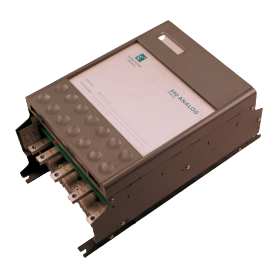
590A SERIES THREE PHASE CONVERTORS
PRODUCT MANUAL
A WARNING GIVES THE READER INFORMATION WHICH IF
DISREGARDED COULD CAUSE INJURY OR DEATH
All rights strictly reserved. No part of this document may be stored in a retrieval system, or transmitted in any form or by any means to persons not
employed by a Eurotherm group company without written permission from Eurotherm Drives Ltd.
Although every effort has been taken to ensure the accuracy of this document it may be necessary, without notice, to make amendments or correct
omissions. Eurotherm Drives cannot accept responsibility for damage, injury, or expenses resulting therefrom.
HA387179 Issue 10
Advertisement
Table of Contents

Related Manuals for Eurotherm 590A SERIES

Summary of Contents for Eurotherm 590A SERIES
- Page 1 All rights strictly reserved. No part of this document may be stored in a retrieval system, or transmitted in any form or by any means to persons not employed by a Eurotherm group company without written permission from Eurotherm Drives Ltd.
- Page 2 +44 (0)117 938 1800 - info@sdsdrives.com WARRANTY Eurotherm Drives warrants the goods against defects in design, materials and workmanship for the period of 12 months from the date of delivery on the terms detailed in Eurotherm Drives Standard Conditions of Sale IA058393C.
- Page 3 APPLICATION RISK: The integration of this product into other apparatus or system is not the responsibility of Eurotherm Drives Ltd as to its applicability, effectivity or safety of operation or of other apparatus or systems. Where appropriate the user should consider some aspects of the following risk assessment.
- Page 4 RCDS: Compatible with Type B RCDs only. CONTROLLER WARRANTY: For further details on Eurotherm Drives Controller Warranty and Repair refer to the Standard Conditions of Sale IA058393C. EUROTHERM DRIVES RESERVE THE RIGHT TO CHANGE OR ALTER THE SPECIFICATION OF THIS...
-
Page 5: Table Of Contents
Requirements for UL508 Outline & Wiring Diagrams 10 THE EUROPEAN DIRECTIVES 4.6 EMC Installation Guidelines 4-19 AND THE ‘CE’ MARK. 10-1 10.1 Eurotherm EMC ‘CE’ Mark 5. TERMINAL DESCRIPTIONS Validity Chart 10-2 5.1 Control Board Certificates 10-6 5.2 Power Board 11 . -
Page 6: Introduction
This manual was downloaded on www.sdsdrives.com +44 (0)117 938 1800 - info@sdsdrives.com 1. INTRODUCTION 1.1 545/590A UPGRADE The 545 Series product has been applied successfully in a wide variety of applications by machine builders and OEM's. This short note is designed to make a quick comparison between the two products and to show just how convenient the application of 590A will be. -
Page 7: To 590A Conversion Chart
This manual was downloaded on www.sdsdrives.com +44 (0)117 938 1800 - info@sdsdrives.com 1.2 545 TO 590A CONVERSION CHART Control Terminals A Function 590A LV Signal Common Armature Current Compensation Setpoint Ramp Reset Setpoint Ramp Input Setpoint Ramp Output Input No 1 Input No 2 Inverted Sub-Total Input No 3... - Page 8 This manual was downloaded on www.sdsdrives.com +44 (0)117 938 1800 - info@sdsdrives.com Control Terminals C LV Power Common Thermistor Input Auxiliary Enable Start Supply Enable Stop Start Ready Zero Speed Relay Drive Drive Operational Relay Drive +24V External Fault Reset Power Terminals AC Field Supply No Connection...
-
Page 9: A Introduction
+44 (0)117 938 1800 - info@sdsdrives.com 1.3 590A INTRODUCTION The 590A series of motor speed controllers are designed as components which are fitted into a standard enclosure with associated control equipment. The controllers accept standard three phase supply voltages in the range 220 to 500 Volt AC. -
Page 10: Technical Specifications
This manual was downloaded on www.sdsdrives.com +44 (0)117 938 1800 - info@sdsdrives.com 2. TECHNICAL SPECIFICATIONS 2.1 SPECIFICATION 2.1.1 Control Enclosure Rating: IP00, to be built into a suitable cubicle. Control Circuits: Fully isolated from power circuit. (SELV) Output Control: Fully controlled 3-phase Thyristor Bridge. Microprocessor implemented phase control over extended firing range. -
Page 11: Power
This manual was downloaded on www.sdsdrives.com +44 (0)117 938 1800 - info@sdsdrives.com Climatic Conditions: Class 3k3, as defined by EN50178 (1998). Atmosphere: Non-flammable, non-condensing. Pollution Degree: Installation/Overvoltage Category : Electrical Safety Standards: UL508, VDE0160 (1994), EN50178 (1998) EMC Standards: See Section 10. 2.1.2 Power Configuration: 590A, 598A*... -
Page 12: Output Ratings
650 Amps overload capacity is as normal. External Stack assemblies at 660V are not available above 2000 Amps without reference to Eurotherm Drives Internal Sales Department. For Installation Drawings for 720A Stock Assembly see: HG049669 Standard Mounting / HG054248 Bracket Mounting. -
Page 13: Field Rating
This manual was downloaded on www.sdsdrives.com +44 (0)117 938 1800 - info@sdsdrives.com 2.2.2 FIELD RATING Output current ratings: 590A/0350-590A/2700 } i.e. from 35A build to 270A build 591A/0350-590A/2700 } 590A/4500 - 590A/7200 } i.e. from 450A build to 720A build 20A 591A/4500 - 591A/7200 } 598A } i.e. - Page 14 This manual was downloaded on www.sdsdrives.com +44 (0)117 938 1800 - info@sdsdrives.com RATING UP TO 450A:190KW (250HP) Mounting Centres: Vertical - 600mm (23.6") Horizontal - 200mm (7.87") Overall Width: 250mm (8.75mm") (322mm (12.7") over dc terminals) Overall Height: 705mm (27.75") Integral Fan 675mm (26.6") Roof Fan Overall Depth: 252mm (9.9")
-
Page 15: Product Code
This manual was downloaded on www.sdsdrives.com +44 (0)117 938 1800 - info@sdsdrives.com 3. PRODUCT CODE 590A AND 591A THREE PHASE CONVERTERS All members of the three phase product range can be fully specified using a digit numerical order code. Block No No of Digits Function Basic Product... -
Page 16: Installation & Wiring Instructions
4. BASIC INSTALLATION AND WIRING INSTRUCTIONS 4.1 INSTALLATION The 590A series motor speed controllers are designed as components which are to be fitted with other control equipment in a suitable enclosure. The control units are all designed to mount directly onto a flat surface. They should be fastened by means of bolts or screws through the fixing points at each corner. - Page 17 A 3 phase ac line reactor should be fitted in series with the incoming main 3 phase ac power supply. (Eurotherm Drives stock a series of reactors suitable for this duty, mechanically designed to connect directly to the controller ac supply terminals). The reactor should be connected between the controller and the ac contactor for optimum protection and safety.
- Page 18 CO057961 suitable for use with 545 series and CO387866 suitable for use with 590 series. Specically for use with EMC filters. DATE DRWN: CHKD TITLE: DRAWING NO: SHT 1 21.04.97 Outline Drawing for 3-phase Line Chokes HG386828C EUROTHERM DRIVES for DC Controllers 1 SHTS 4 - 3...
- Page 19 Note: When the controller is operating in a regenerative mode for extended periods acting as a load generator for another machine it is advisable to fit additional protection in the armature circuit. A dc fuse or a high speed circuit breaker will provide this protection, if in doubt consult the Eurotherm Drives Engineering Department.
-
Page 20: Notes On Wiring
To avoid damaging the drive NEVER carry out high voltage resistance or dielectric strength tests without first completely disconnecting the drive from the circuit being tested. If in doubt about the connection of the dc motor to the controller check with Eurotherm Drives Engineering Department. -
Page 21: Requirements For Ul508
This manual was downloaded on www.sdsdrives.com +44 (0)117 938 1800 - info@sdsdrives.com 4.5 ADDITIONAL INSTALLATION REQUIREMENTS FOR UL 508 AMERICAN STYLE FUSES (For use where compliance to UL 508 is required) PRODUCT CONTROLLER THYRISTOR I²T SEMICONDUCTOR FUSES CODE RATING PART NO. BLOCK 2 AMPS JUNC... - Page 22 This manual was downloaded on www.sdsdrives.com +44 (0)117 938 1800 - info@sdsdrives.com...
- Page 23 This manual was downloaded on www.sdsdrives.com +44 (0)117 938 1800 - info@sdsdrives.com...
- Page 24 This manual was downloaded on www.sdsdrives.com +44 (0)117 938 1800 - info@sdsdrives.com...
- Page 25 This manual was downloaded on www.sdsdrives.com +44 (0)117 938 1800 - info@sdsdrives.com...
- Page 26 This manual was downloaded on www.sdsdrives.com +44 (0)117 938 1800 - info@sdsdrives.com...
- Page 27 This manual was downloaded on www.sdsdrives.com +44 (0)117 938 1800 - info@sdsdrives.com...
- Page 28 This manual was downloaded on www.sdsdrives.com +44 (0)117 938 1800 - info@sdsdrives.com...
- Page 29 This manual was downloaded on www.sdsdrives.com +44 (0)117 938 1800 - info@sdsdrives.com...
- Page 30 This manual was downloaded on www.sdsdrives.com +44 (0)117 938 1800 - info@sdsdrives.com...
- Page 31 This manual was downloaded on www.sdsdrives.com +44 (0)117 938 1800 - info@sdsdrives.com...
- Page 32 This manual was downloaded on www.sdsdrives.com +44 (0)117 938 1800 - info@sdsdrives.com...
- Page 33 This manual was downloaded on www.sdsdrives.com +44 (0)117 938 1800 - info@sdsdrives.com...
-
Page 34: Emc Installation Guidelines
The subject of EMC is explored in more detail in a separate Eurotherm Application Manual entitled “EMC Installation Guidelines for Modules and Systems”, part number HA388879, available from your local Eurotherm office. - Page 35 This manual was downloaded on www.sdsdrives.com +44 (0)117 938 1800 - info@sdsdrives.com Figure 4.1 Filter Mounting Details Part No. CO388965U035 for 590 35amp Figure 4.2 Filter Mounting Details Part No. CO388965U110 for 590 70 & 110amp 4 - 20...
- Page 36 This manual was downloaded on www.sdsdrives.com +44 (0)117 938 1800 - info@sdsdrives.com Figure 4.3 Filter Mounting Details Part No. CO388965U180 for 590 360 amp Figure 4.4 Filter Mounting Details Part No. CO389456 for 590 270 amp 4 - 21...
- Page 37 This manual was downloaded on www.sdsdrives.com +44 (0)117 938 1800 - info@sdsdrives.com Figure 4.5 Filter Mounting Details using 2x Part No. CO389456 for 590 360amp These filters and chokes may be mounted to the left, right, above, below or spaced behind the product, but can be mounted in two orientations i) flat against the wall or ii) projecting out from the wall, mounting arrangements are shown in figures 4.1 - 4.5.
- Page 38 As with all power electronic drives the conducted emissions increase with motor cable length. EMC conformance to the stringent limits is only guaranteed up to a cable length of 50. This length can be increased. Refer to Eurotherm Drives for more information.
- Page 39 Under certain fault conditions, larger DC protective earth currents may flow. The pro- tective function of some RCDs cannot be guaranteed under such operating conditions. Eurotherm Drives do not recommend the use of RCDs, but where their use is mandatory, they should be capable of correct operation with DC and AC protective earth currents (such as type B RCDs as in amendment 2 of IEC755) and have adjustable trip amplitude and time characteristics, to prevent nuisance tripping on initial power connection.
- Page 40 This manual was downloaded on www.sdsdrives.com +44 (0)117 938 1800 - info@sdsdrives.com Motor Motor Cable Screen Filter + Choke Supply As short In close proximity as possible to drive Safety Earth Fig. 4-6: Screening and earthing of a single 590 drive module. When more than one piece of electrical equipment is fitted inside an enclosure, care must be taken to ensure that noise flowing in the earth connection does not couple into other equipment.
- Page 41 This manual was downloaded on www.sdsdrives.com +44 (0)117 938 1800 - info@sdsdrives.com To Motor To Motor To Motor Screened Screened PE = protective earth OA = analogue 0volts Power Screen Earth OD = digital 0volts Sig/cntrl Screen AC/DC AC/DC AC/DC Unscreened Signals Unscreened...
- Page 42 This manual was downloaded on www.sdsdrives.com +44 (0)117 938 1800 - info@sdsdrives.com Often the coupling between electrically 'noisy' and 'sensitive' cables is a problem. This can be minimised by separating parallel runs by at least 0.25m, and minimising the length of parallel runs. For long parallel runs (>10 m) the separation should be increased proportionally.
-
Page 43: Terminal Descriptions
This manual was downloaded on www.sdsdrives.com +44 (0)117 938 1800 - info@sdsdrives.com 5. TERMINAL DESCRIPTIONS 5.1 CONTROL BOARD TERMINAL DESCRIPTIONS * These Terminals should be left open-circuit if not used. AC TACH INPUT AC TACH INPUT These terminals provide input for AC tach speed measurement, rectification and filtering are provided. Selection of AC tach feedback is made via switch 1 selection. - Page 44 This manual was downloaded on www.sdsdrives.com +44 (0)117 938 1800 - info@sdsdrives.com INPUT NO. 1* Speed Reference input. Maximum input = +/-10V with respect to 0V, input impedance = 20K Ohms. See also Inverted Subtotal, terminal 11 and Total Setpoint terminal 13 INPUT NO.
- Page 45 This manual was downloaded on www.sdsdrives.com +44 (0)117 938 1800 - info@sdsdrives.com to flow. The maximum level of this signal is later modified by the Current Limit circuit (according to the input voltages at terminals 22,23 and 25) before comparison with the Current Feedback signal SELECT AUXILIARY CURRENT INPUT* If this Terminal is connected to 0V any input at terminal 20 will be connected through to the input of the Current loop and will be added to the Current Demand Signal (see also Current Demand Isolate, Terminal...
- Page 46 This manual was downloaded on www.sdsdrives.com +44 (0)117 938 1800 - info@sdsdrives.com Zero Volt reference THERMISTOR/MICROTHERM Motor overtemperature sensors should be connected between Terminals 28 and 29. The drive will be disabled if the external resistance between 28 and 29 exceeds 1.8K Ohms +/-200 Ohms (see 35 and 37 Terminal descriptions).
-
Page 47: Power Board
This manual was downloaded on www.sdsdrives.com +44 (0)117 938 1800 - info@sdsdrives.com Auxiliary Enable input voltage (Terminal 30) +24V. Armature current waveform normal. ZERO SPEED RELAY DRIVE This output is intended to supply a +24 volt (D.C.) relay at an output current not exceeding 50mA. The relay should be connected between Terminals 36 and 0V;... - Page 48 This manual was downloaded on www.sdsdrives.com +44 (0)117 938 1800 - info@sdsdrives.com NOTE:- The contacts of the Contactor Control Relay are suppressed by a series connected resistor (680 ohms) and capacitor (22nF) to protect the relay contacts. Users should be aware that when the contactor Control relay is “De-energised”, a leakage current of approximately 2mA can be expected and this should be considered when interfacing to these terminals.
-
Page 49: Block Diagram Description
This manual was downloaded on www.sdsdrives.com +44 (0)117 938 1800 - info@sdsdrives.com 6. BLOCK DIAGRAM DESCRIPTION 6.1. POWER CONFIGURATION Three phase power is supplied to the AC input terminals (L1, L2 and L3) of the drive via an external isolating contactor. - Page 50 This manual was downloaded on www.sdsdrives.com +44 (0)117 938 1800 - info@sdsdrives.com 5. An isolated speed feedback signal is provided by a tach or from the armature voltage using a 5590 Armature voltage isolation amplifier. It is then normalised to 10V = 100% Full Speed. 6.
- Page 51 This manual was downloaded on www.sdsdrives.com +44 (0)117 938 1800 - info@sdsdrives.com The speed feedback is scaled within the drive using the calibration switches for coarse adjustment: S2 - 0/100 Volts S3 - 0/ 90 Volts S4 - 0/ 9 Volts This allows an adjustment calibration factor for full speed up to 199 Volts.
-
Page 52: Start And Stop Sequencing
This manual was downloaded on www.sdsdrives.com +44 (0)117 938 1800 - info@sdsdrives.com For any current setting between 110% and 200% of full load, the actual current level is monitored by an overload integrating circuit. The output of this circuit pulls down the current limit setting progressively to 110% at a rate which is proportional to the overload magnitude, i.e., An inverse time characteristic which typically allows 200% current for ten seconds after which the level is automatically reduced to 110% , on a time curve which would allow 150% for about 30 seconds, and so on. - Page 53 This manual was downloaded on www.sdsdrives.com +44 (0)117 938 1800 - info@sdsdrives.com ALARM SIGNALS The inputs to the eight input "AND" gate are: 1) PRESET BOARD: The Preset board is electrically interlocked. In the event of its removal or absence the drive is quenched and Indicator 1 is extinguished (Note: removal of the preset board whilst the drive is operating is not recommended).
- Page 54 This manual was downloaded on www.sdsdrives.com +44 (0)117 938 1800 - info@sdsdrives.com ENABLE An external Enable (Terminal 32 ) is gated with the Ready Output to produce the final inhibit signal. The drive may therefore be held in a quench condition by removing the external Enable, although the 3-phase isolating contactor is still closed.
- Page 55 This manual was downloaded on www.sdsdrives.com +44 (0)117 938 1800 - info@sdsdrives.com...
- Page 56 This manual was downloaded on www.sdsdrives.com +44 (0)117 938 1800 - info@sdsdrives.com...
-
Page 57: Basic Setting Up & Operating Instructions
This manual was downloaded on www.sdsdrives.com +44 (0)117 938 1800 - info@sdsdrives.com 7.0 BASIC SETTING UP AND OPERATING INSTRUCTIONS 7.1 PRESET ADJUSTMENT DESCRIPTION Check the preset potentiometer settings on the larger plug-in card which is accessible under the front cover. The potentiometers are normally factory set to positions which will provide adequate performance in most load/controller configurations. -
Page 58: Option Switches
This manual was downloaded on www.sdsdrives.com +44 (0)117 938 1800 - info@sdsdrives.com 7.2 OPTION SWITCHES There are two user selectable option switches S8 and S9, which are located under the lower flap of the control board. Selection should only be made when the controller is isolated. S8/1 BUFFERED CURRENT SIGNAL (terminal 27) UP = ON = Armature current meter reads ±... - Page 59 This manual was downloaded on www.sdsdrives.com +44 (0)117 938 1800 - info@sdsdrives.com S9/2 FULL WAVE FIELD SUPPLY UP = ON = Full wave rectification field supply. Typically using 415V single phase supply the field voltage will be 360V DC nominal.* DOWN = OFF = No field supply from this option.
-
Page 60: Calibration
Values are selected in the factory on the basis of the best combination of standard resistor values. NOTE: The armature current calibration switches should not be changed to increase the current above the factory set value without consulting Eurotherm Drives Limited Engineering Department. 7 - 4... -
Page 61: Field Voltage Calibration
This manual was downloaded on www.sdsdrives.com +44 (0)117 938 1800 - info@sdsdrives.com 7.3.3 FIELD VOLTAGE CALIBRATION Field voltage calibration is set by selection of the option switches S9/1/2/3/4 (see S9 description). When S9/4 is selected, the field voltage can be adjusted by preset P11. By using the selection of S9/4 and P11, the most accurate setting of field voltage can be achieved. -
Page 62: Checking The Drive & Setting Up
This manual was downloaded on www.sdsdrives.com +44 (0)117 938 1800 - info@sdsdrives.com Refer to Section 7.1 The one exception to this is the main current limit preset; note the setting of this control and then turn it fully anticlockwise. Refer to section 7.1. 6. - Page 63 This manual was downloaded on www.sdsdrives.com +44 (0)117 938 1800 - info@sdsdrives.com WARNING: DO NOT PROCEED FURTHER UNLESS THE STOP/START CIRCUITS AND CONTACTOR OPERATE CORRECTLY. 7. Turn off all power supplies to the equipment and when the whole system is totally isolated and safe, reconnect the Main 3-phase power supply.
-
Page 64: Running Performance Adjustments
The Proportional and Integral potentiometers (P5, P6, P8 and P9), as preset by Eurotherm Drives Limited, will provide stable and responsive performance under most load conditions. Thus if instability is observed it is... - Page 65 This manual was downloaded on www.sdsdrives.com +44 (0)117 938 1800 - info@sdsdrives.com 4. To achieve Full Load Current it is necessary to override the Tach Failure Alarm/Clamp: Disconnect the Tach (+) wire from terminal 3 and then link terminal 3 to ±10V (terminal 14, 15, or 24). 5.
- Page 66 This manual was downloaded on www.sdsdrives.com +44 (0)117 938 1800 - info@sdsdrives.com...
- Page 67 This manual was downloaded on www.sdsdrives.com +44 (0)117 938 1800 - info@sdsdrives.com 8. When the Current Loop response adjustment is completed, switch off the drive and disconnect all supplies. REMOVE THE LINK FROM BETWEEN TERMINAL 3 AND THE 10V SUPPLY AND THEN RECONNECT THE TACHO (+) WIRE TO TERMINAL 3.
- Page 68 This manual was downloaded on www.sdsdrives.com +44 (0)117 938 1800 - info@sdsdrives.com...
-
Page 69: Description Of Diagnostic Test Unit
This manual was downloaded on www.sdsdrives.com +44 (0)117 938 1800 - info@sdsdrives.com 8. DIAGNOSTIC TEST FACILITY 8.1 DESCRIPTION OF DIAGNOSTIC TEST UNIT The drive is fitted with a multi-pin socket near the lower edge of the Main Control printed circuit board to allow connection of a type 5570 Diagnostic Test Unit. - Page 70 This manual was downloaded on www.sdsdrives.com +44 (0)117 938 1800 - info@sdsdrives.com LED3: 3-PHASE POWER SUPPLY 3-Phase power supply connected. OFF: 1 Phase or more not connected. Main contactor not closed. Main fuse failure check . Coding fuse failure check FS2, FS3, FS4. LED4: NORMAL/OVER CURRENT FAULT Armature Current Normal.
-
Page 71: Drive Condition Indicators Status Recognition
This manual was downloaded on www.sdsdrives.com +44 (0)117 938 1800 - info@sdsdrives.com 8.5 DRIVE CONDITION INDICATORS STATUS RECOGNITION 8.5.1. STOP CONDITION CONDITION REFERENCE STOP CONDITION 1 PHASE (AUX) ON/OFF 45-65HZ ENABLE/INHIBIT LED ON 3-PHASE (MAINS) ON/OFF LED OFF NORMAL/OVERCURRENT FAULT ⊗... -
Page 72: Start Condition
This manual was downloaded on www.sdsdrives.com +44 (0)117 938 1800 - info@sdsdrives.com 8.5.2 START CONDITION CONDITION REFERENCE START CONDITION 1 PHASE (AUX) ON/OFF 45-65HZ ENABLE/INHIBIT LED ON 3-PHASE (MAINS) ON/OFF LED OFF NORMAL/OVERCURRENT FAULT ⊗ EITHER RUN/INHIBIT ROTATING/STANDSTILL NORMAL/ALARM CONDITIONS/CHECKS NORMAL STOP CONDITION ⊗... - Page 73 This manual was downloaded on www.sdsdrives.com +44 (0)117 938 1800 - info@sdsdrives.com 8.5.2 START CONDITION Continued... CONDITION REFERENCE START CONDITION 1 PHASE (AUX) ON/OFF 45-65HZ ENABLE/INHIBIT LED ON 3-PHASE (MAINS) ON/OFF LED OFF NORMAL/OVERCURRENT FAULT ⊗ EITHER RUN/INHIBIT ROTATING/STANDSTILL NORMAL/ALARM CONDITIONS/CHECKS NORMAL RUN CONDITION - SHAFT STATIONARY IF INCREASING SETPOINT HAS NO EFFECT THEN:...
- Page 74 This manual was downloaded on www.sdsdrives.com +44 (0)117 938 1800 - info@sdsdrives.com 8.5.2 START CONDITION Continued... CONDITION REFERENCE START CONDITION 1 PHASE (AUX) ON/OFF 45-65HZ ENABLE/INHIBIT LED ON 3-PHASE (MAINS) ON/OFF LED OFF NORMAL/OVERCURRENT FAULT ⊗ EITHER RUN/INHIBIT ROTATING/STANDSTILL NORMAL/ALARM CONDITIONS/CHECKS ⊗...
-
Page 75: Diagnostic Test Unit Voltage Measurements
This manual was downloaded on www.sdsdrives.com +44 (0)117 938 1800 - info@sdsdrives.com 8.5.3 DIAGNOSTIC TEST UNIT - VOLTAGE MEASUREMENTS TEST DIAGNOSTIC TEST POINT DESCRIPTION CONDITION VOLTAGE INTERNAL +15V SUPPLY Aux. Power ON +15V ±0.25V Max. 100Hz ripple=25mV peak to peak EXTERNAL +10V SUPPLY Aux. - Page 76 This manual was downloaded on www.sdsdrives.com +44 (0)117 938 1800 - info@sdsdrives.com 8.5.3 DIAGNOSTIC TEST UNIT - VOLTAGE MEASUREMENTS TEST DIAGNOSTIC TEST POINT DESCRIPTION CONDITION VOLTAGE SETPOINT RAMP RESET (SEE S8/6) Enable = Open circuit to terminal 6 Ramp Enable AND Run +15V Reset to Zero = Connect terminal 6 to 0V Ramp Reset OR Stop...
- Page 77 This manual was downloaded on www.sdsdrives.com +44 (0)117 938 1800 - info@sdsdrives.com 8.5.3 DIAGNOSTIC TEST UNIT - VOLTAGE MEASUREMENTS TEST DIAGNOSTIC TEST POINT DESCRIPTION CONDITION VOLTAGE CURRENT DEMAND ISOLATE Connects directly to terminal 18. Note: 1. For speed control operation leave terminal Speed control +15V 18 open circuit.
- Page 78 This manual was downloaded on www.sdsdrives.com +44 (0)117 938 1800 - info@sdsdrives.com 8.5.3 DIAGNOSTIC TEST UNIT - VOLTAGE MEASUREMENTS TEST DIAGNOSTIC TEST POINT DESCRIPTION CONDITION VOLTAGE MAIN CURRENT LIMIT Overrides Auxiliary Current Limits Variable Voltage depending upon 0 to +10V (see Diagnostic 22 and 23).
- Page 79 This manual was downloaded on www.sdsdrives.com +44 (0)117 938 1800 - info@sdsdrives.com 8.5.3 DIAGNOSTIC TEST UNIT - VOLTAGE MEASUREMENTS TEST DIAGNOSTIC TEST POINT DESCRIPTION CONDITION VOLTAGE PHASE ANGLE Variable Signal in run condition: This signal is held to zero except in the run Positive phase angle.
- Page 80 This manual was downloaded on www.sdsdrives.com +44 (0)117 938 1800 - info@sdsdrives.com 9 590 "ALL IN ONE" POWER BOARD (REF AH058426U002/003) DESCRIPTION A new 590 Power Board has been introduced that includes in one single PCB all the circuits of the previous split-in-three power board (referred to next as the "old"...
- Page 81 This manual was downloaded on www.sdsdrives.com +44 (0)117 938 1800 - info@sdsdrives.com COOLING FAN CONNECTIONS When the controller is fitted with heatsink cooling fans then these fans are connected to FAN LIVE (F27) FAN NEUTRAL (F24) and where appropriate FAN COMMON (F23). If the auxiliary supply is 110/115V and two cooling fans are fitted, the two fans are connected in parallel to FAN LIVE (F27) and FAN NEUTRAL (F24) and similarly, if the auxiliary supply is 220/240V then the two fans are connected in series, the FAN COMMON (F23) providing the centre point.
- Page 82 This manual was downloaded on www.sdsdrives.com +44 (0)117 938 1800 - info@sdsdrives.com...
- Page 83 This manual was downloaded on www.sdsdrives.com +44 (0)117 938 1800 - info@sdsdrives.com...
- Page 84 This manual was downloaded on www.sdsdrives.com +44 (0)117 938 1800 - info@sdsdrives.com...
- Page 85 This manual was downloaded on www.sdsdrives.com +44 (0)117 938 1800 - info@sdsdrives.com 590 POWER BOARD (AH385621) Replaces AH055050 From August 1995. Power supply specification as AH385851 described above. Product Type 590/7200 (4Q 720amp) 591/7200 (2Q 720amp) Subject of enhancement Power Board now updated to AH385621U001 (Sep 1995) This item has been updated to include improvements including: Surface Mount Technology Revised SMPS (as 590/592)
-
Page 86: The European Directives And The 'Ce' Mark
EMC DIRECTIVE 'CE' EMC Responsibility The subject of CE marking and EMC is explored in more detail in a separate Eurotherm Application manual entitled ‘EMC Installation Guidelines for modules and systems’, part number HA388879, available from your local Eurotherm Drives office. The following sections are the minimum necessary for basic understanding. -
Page 87: Eurotherm Emc 'Ce' Mark Validity Chart
This manual was downloaded on www.sdsdrives.com +44 (0)117 938 1800 - info@sdsdrives.com Figure 10.1 Eurotherm EMC ‘CE’ Mark Validity Chart START IS E.D. MODULE RELEVANT APPARATUS WITH INTRINSIC FUNCTION TO END USER (CEMEP VALIDITY FIELD 1) CEMEP VALIDITY FIELDS 2, 3 AND 4 OPTIONAL E.D. - Page 88 This manual was downloaded on www.sdsdrives.com +44 (0)117 938 1800 - info@sdsdrives.com CONSIDERATION OF EMC ENVIRONMENT When considering the relevant EMC emission and immunity standards it is important to distinguish between the following classes of EMC environments: Residential, supplied Commercial and Industrial directly from public light industry,...
- Page 89 EMC Drive Product Standard to demonstrate conformance using the technical construction file route. The EMC Drive Product Standard as CEMEP is discussed in more detail in the Eurotherm Application manual entitled ‘EMC Installation Guidelines for modules and systems’, part number HA388879, available from your local Eurotherm Drives office.
- Page 90 EMC conformance and applying the 'CE' mark and issuing an EC Declaration of Conformity. Eurotherm Guide More information is available in a separate Eurotherm Guide entitled “Short Form Overview of European Directives for Variable Speed Drives and Applications” part number HA389770 available from your local Eurotherm Drives office.
-
Page 91: Certificates
93/68/EEC, Article 10 and Annex 1, (EMC the low voltage DIRECTIVE) DIRECTIVE) the unit is used directive for We Eurotherm Drives Limited, address as We Eurotherm Drives Limited, address as as relevant electrical below, declare under our sole responsibility below, declare under our sole responsibility apparatus. -
Page 92: Identification List
This manual was downloaded on www.sdsdrives.com +44 (0)117 938 1800 - info@sdsdrives.com 11. SPARES KITS AND SPARE PART IDENTIFICATION LIST All spares requirements for the 590A/591A product family can be specified using an alpha-numeric code. For installations of 5 or more drives we recommend the holding of a complete spare drive. For installations of up to 5 drives we recommend the holding of a Spares Kit which can be ordered using the Product Code and therefore saves time, obtains the best price and reduces the risk of poor spares coverage. - Page 93 This manual was downloaded on www.sdsdrives.com +44 (0)117 938 1800 - info@sdsdrives.com TABLE 1 - PRODUCT RATING 590A PRODUCT 35.0 70.0 110.0 150.0 180.0 270.0 360.0 450.0 720.0 XXXX.X RATING 590A SPARES KIT SPARE_4/590A/ SPARE_4/590A/ SPARE_4/590A/ SPARE_4/590A/ SPARE_4/590A/ SPARE_4/590A/ SPARE_4/590A/ SPARE_4/590A/ SPARE_4/590A/ SPARE_5/598A/...
- Page 94 This manual was downloaded on www.sdsdrives.com +44 (0)117 938 1800 - info@sdsdrives.com TABLE 2 - PRODUCT RATING 591A PRODUCT 35.0 70.0 110.0 150.0 180.0 270.0 360.0 450.0 720.0 XXXX.X RATING 591A SPARES KIT SPARE_4/591A/ SPARE_4/591A/ SPARE_4/591A/ SPARE_4/591A/ SPARE_4/591A/ SPARE_4/591A/ SPARE_4/591A/ SPARE_4/591A/ SPARE_4/591A/ SPARE_5/599A/...
-
Page 95: Service Information
(see HG 049669) Maintenance is always enhanced by the availability of spares sufficient to minimise down time. Never forget that maintenance is more effective if your engineers have been properly trained. Eurotherm Drives operate a training program especially tailored for your requirement. - Page 96 This manual was downloaded on www.sdsdrives.com +44 (0)117 938 1800 - info@sdsdrives.com Disposal This product contains materials which are consignable waste under the Special Waste Regulations 1996 which complies with the EC Hazardous Waste Directive – Directive 91/689/EEC. We recommend you dispose of the appropriate materials in accordance with the valid environmental control laws.
- Page 97 This manual was downloaded on www.sdsdrives.com +44 (0)117 938 1800 - info@sdsdrives.com...
- Page 98 This manual was downloaded on www.sdsdrives.com +44 (0)117 938 1800 - info@sdsdrives.com...
- Page 99 This manual was downloaded on www.sdsdrives.com +44 (0)117 938 1800 - info@sdsdrives.com...
- Page 100 This manual was downloaded on www.sdsdrives.com +44 (0)117 938 1800 - info@sdsdrives.com...
- Page 101 This manual was downloaded on www.sdsdrives.com +44 (0)117 938 1800 - info@sdsdrives.com...
- Page 102 This manual was downloaded on www.sdsdrives.com +44 (0)117 938 1800 - info@sdsdrives.com...
- Page 103 This manual was downloaded on www.sdsdrives.com +44 (0)117 938 1800 - info@sdsdrives.com...
- Page 104 This manual was downloaded on www.sdsdrives.com +44 (0)117 938 1800 - info@sdsdrives.com...
- Page 105 This manual was downloaded on www.sdsdrives.com +44 (0)117 938 1800 - info@sdsdrives.com...
- Page 106 This manual was downloaded on www.sdsdrives.com +44 (0)117 938 1800 - info@sdsdrives.com...
- Page 107 This manual was downloaded on www.sdsdrives.com +44 (0)117 938 1800 - info@sdsdrives.com...
- Page 108 This manual was downloaded on www.sdsdrives.com +44 (0)117 938 1800 - info@sdsdrives.com...
-
Page 109: Disposal & Packaging
EARTH/GROUND THE MOTOR THROUGH THE 590 with ‘ DRIVE’ DO NOT ... ENCLOSURE’. Page 4-2 added ‘9. EMC ... contactor’ 4-19 added Total Filter Watt Loss columns. FIRST USED ON MODIFICATION RECORD 590A Product Manual SHT.2 DRAWING NUMBER EUROTHERM DRIVES ZZ387179 OF 2...
Need help?
Do you have a question about the 590A SERIES and is the answer not in the manual?
Questions and answers