Table of Contents
Advertisement
Advertisement
Table of Contents
Troubleshooting

Related Manuals for Cooper & Hunter CH-S12FTXQ (WI-FI)


Summary of Contents for Cooper & Hunter CH-S12FTXQ (WI-FI)
- Page 1 SERVICE MANUAL Split Air Conditioner VERITAS INVERTER Series M ODEL : CH-S 12 FT XQ (WI-FI) CH-S 18 FT XQ (WI-FI) For proper operation, please read and keep this manual carefully. Designed by Cooper&Hunter International Corporation, Oregon, USA www.cooperandhunter.com...
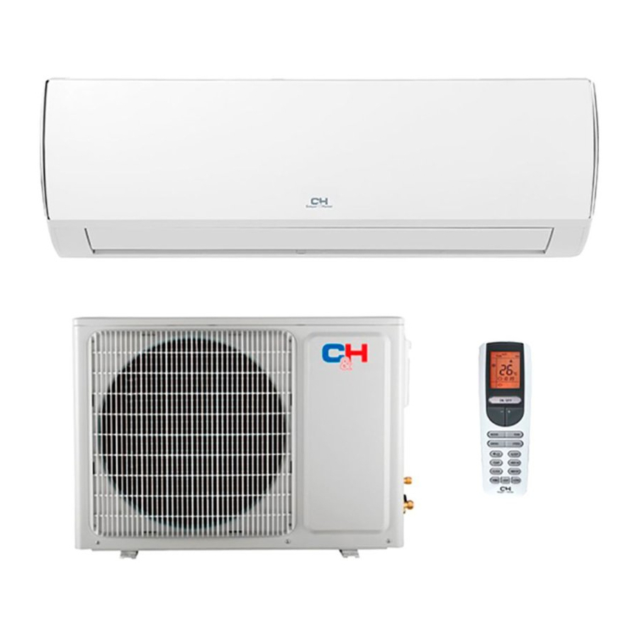
- Page 2 Part Ⅰ : Technical Information 1. Summary Indoor Unit Outdoor Unit Remote Controller...
-
Page 3: Specifications
2. Specifications 2.1 Specification Sheet Model CH-S12FTXQ (Wi-Fi) Product Code CB470001101 Rated Voltage 220-240 Power Rated Frequency Supply Phases Power Supply Mode Outdoor Cooling Capacity(Min~Max) 3500 Heating Capacity(Min~Max) 3600 Cooling Power Input(Min~Max) Heating Power Input(Min~Max) Cooling Current Input 4.50 Heating Current Input Rated Input 1500 Rated Cooling Current... - Page 4 Model of Outdoor Unit CH-S12FTXQ (Wi-Fi) Product Code of Outdoor Unit CB427W04701 Compressor Manufacturer/Trademark Zhuhai Landa Compressor Co.; Ltd. Compressor Model QXA-B102zE190 Compressor Oil RB68EP Compressor Type Rotary L.R.A. 35.00 Compressor RLA 4.80 Compressor Power Input 1020 Overload Protector Throttling Method Capillary Operation temp 16~30...
- Page 5 CH-S18FTXQ (Wi-Fi) Model CB460003800 Product Code Rated Voltage 220-240 Power Rated Frequency Supply Phases Power Supply Mode Outdoor Cooling Capacity(Min~Max) 5000 Heating Capacity(Min~Max) 5300 Cooling Power Input(Min~Max) 1430 Heating Power Input(Min~Max) 1380 Cooling Current Input 6.34 Heating Current Input 6.12 Rated Input 1860 Rated Cooling Current...
- Page 6 Model of Outdoor Unit CH-S18FTXQ (Wi-Fi) Product Code of Outdoor Unit CB427W06400 Compressor Manufacturer/Trademark Zhuhai Landa Compressor Co.; Ltd. Compressor Model QXA-B102zE190A Compressor Oil FVC68D or RB68EP Compressor Type Rotary L.R.A. 35.00 Compressor RLA 4.80 Compressor Power Input 1020 Overload Protector Throttling Method Capillary Operation temp...
-
Page 7: Operation Characteristic Curve
2.2 Operation Characteristic Curve Cooling Heating 220V Conditions 220V Indoor: DB27°C/WB19°C Outdoor: DB35°C/WB24°C Indoor air flow: High Pipe length: 5m 230V 230V 240V Conditions Indoor: DB20°C/WB15°C 240V Outdoor: DB7°C/WB6°C Indoor air flow: High Pipe length: 5m 10 20 30 40 50 60 70 80 90 100 Compressor speed (rps) Compressor speed (rps) 2.3 Capacity Variation Ratio According to Temperature... - Page 8 Heating operation ambient temperature range is -22ºC~24ºC Cooling Heating Conditions Indoor:DB20°C/WB15°C Indoor air flow:Super High Pipe length: 5m Conditions Outdoor temp.( Indoor:DB27°C/WB19°C Indoor air flow:Super High Pipe length: 5m Outdoor temp.(°C) 2.4 Cooling and Heating Data Sheet in Rated Frequency Cooling: Rated cooling Pressure of gas pipe...
-
Page 9: Noise Curve
2.5 Noise Curve Outdoor side noise Indoor side noise High Super High Middle Indoor Fan Motor Rotating Speed Compressor frequency/Hz... -
Page 10: Outline Dimension Diagram
3. Outline Dimension Diagram 3.1 Indoor Unit 168.5 159.5 Φ55 Φ55 Φ55 Φ55 Unit:mm Models... - Page 11 3.2 Outdoor Unit Unit:mm...
-
Page 12: Refrigerant System Diagram
4. Refrigerant System Diagram Cooling and heating model Outdoor unit Indoor unit Gas pipe side Valve 4-Way valve Di s charge Heat Accumlator Suction exchanger Compressor (evaporator) Heat exchanger Liquid pipe (condenser) side Valve Strainer Capillary Strainer COOLING HEATING Connection pipe specification: Liquid pipe:1/4"... -
Page 13: Electrical Part
5. Electrical Part 5.1 Wiring Diagram ●Instruction Symbol Symbol Color Symbol Symbol Color Symbol Name White Green Jumper cap Yellow Brown COMP Compressor Blue Grounding wire YEGN Yellow/Green Black Violet Orange Note: Jumper cap is used to determine fan speed and the swing angle of horizontal lover for this model. ●... - Page 14 ● Outdoor Unit 63610000453 63610000467 These circuit diagrams are subject to change without notice, please refer to the one supplied with the unit.
-
Page 15: Pcb Printed Diagram
5.2 PCB Printed Diagram Indoor Unit ● Top view 1 Neutral wire terminal 2 Interface of health function neutral wire 3 Motor needle stand 4 Interface of health function live wire 5 Auto button 6 Up&down swing motor 7 Interface of up & down swing motor 8 WIFI 9 Temperature sensor 10 Terminal for display board connection... - Page 16 Outdoor Unit ● Top view NAME Interface of electronic expansion valve Overload interface of compressor Terminal of DRED Interface of temperature sensor Main board of IC Eeprom Interface of compressor wire WVU Reactor wiring terminal DRED Live wire interface Interface of electric heating 4-way valve terminal DRED Interface of netural wire Terminal of outdoor fan...
-
Page 17: Notes For Installation And Maintenance
Part Ⅱ : Installation and Maintenance 7. Notes for Installation and Maintenance Safety Precautions: 10. If the power cord or connection wire is not long enough, please get the specialized power cord or connection wire Important! from the manufacture or distributor. Prohibit prolong the wire by yourself. - Page 18 Safety Precautions for Installing and Relocating the Unit: To ensure safety, please be mindful of the following precautions. Warnings 1. When installing or relocating the unit, be sure to keep the refrigerant circuit free from air or substances other than the specified refrigerant. Any presence of air or other foreign substance in the re- frigerant circuit will cause system pressure rise or com- pressor rupture,resulting in injury.
- Page 19 Main Tools for Installation and Maintenance 1. Level meter, measuring tape 2. Screw driver 3. Impact drill, drill head, electric drill 4. Electroprobe 5. Universal meter 6. Torque wrench, open-end wrench, inner hexagon spanner 7. Electronic leakage detector 8. Vacuum pump 9.
-
Page 20: Installation Dimension Diagram
8. Installation 8.1 Installation Dimension Diagram Space to the wall Space to the wall At least 15cm At least 15cm Drainage pipe... -
Page 21: Installation Procedures
Installation procedures Start installation Preparation before installation Read the requirements select installation Prepare tools for electric connection location Select indoor unit Select outdoor unit installation location installation location Install the support of outdoor unit Install wall-mounting frame, drill wall holes (select it according to the actual situation) Connect pipes of indoor Fix outdoor unit... -
Page 22: Requirements For Electric Connection
8.2 Installation Parts-checking 8.4 Requirements for electric connection Name Name 1. Safety Precaution Indoor unit Sealing gum (1) Must follow the electric safety regulations when installing Outdoor unit Wrapping tape the unit. Support of outdoor (2) According to the local safety regulations, use qualified Connection pipe unit power supply circuit and air switch. - Page 23 in the holes. 5. Connect the Pipe of Indoor Unit (3) Fix the wall-mounting frame on the wall with tapping screws (1) Aim the pipe joint at the corresponding bellmouth.(As show (ST4.2X25TA) and then check if the frame is firmly installed by in Fig.5) pulling the frame.
- Page 24 7. Connect Wire of Indoor Unit 8. Bind up Pipe (1) Open the panel, remove the screw on the wiring cover and (1) Bind up the connection pipe, power cord and drain hose then take down the cover.(As show in Fig.11) with the band.(As show in Fig.14) (2) Reserve a certain length of drain hose and power cord Screw...
-
Page 25: Installation Of Outdoor Unit
Refer to the following table for wrench moment of force: 8.6 Installation of Outdoor Unit Tightening torque(N . m) Hex nut diameter(mm) 1. Fix the Support of Outdoor Unit(Select it according to Φ6 15~20 the actual installation situation) Φ9.52 30~40 Φ12 45~55 (1) Select installation location according to the house structure. - Page 26 8.8 Check after Installation and Test (3) The water outlet cant be placed in water in order to drain smoothly.(As show in Fig.27) Operation 1. Check after Installation Check according to the following requirement after finishing installation. The drain hose can't be fluctuant Items to be checked Possible malfunction Has the unit been...
-
Page 27: Error Code List
9. Maintenance 9.1 Error Code List Display Method of Indoor Unit Indicator Display (during blinking, ON 0.5s and OFF Dual-8 Malfunction A/C status Possible Causes 0.5s) Code Name Operation Cool Heating Display Indicator Indicator Indicator Possible reasons: During cooling and drying High 1. - Page 28 Display Method of Indoor Unit Indicator Display (during blinking, Dual-8 Malfunction ON 0.5s and OFF 0.5s) A/C status Possible Causes Code Name Operation Cool Heating Display Indicator Indicator Indicator When the outdoor unit receive signal of Gathering Gathering refrigerant ,the system will Nominal cooling mode refrigerant be forced to run under cooling mode for...
- Page 29 Display Method of Indoor Unit Indicator Display (during blinking, ON 0.5s and OFF Dual-8 Malfunction A/C status Possible Causes 0.5s) Code Name Operation Cool Heating Display Indicator Indicator Indicator Decrease Overload or temperature is too high; frequency All loads operate normally, while Refrigerant is insufficient;...
- Page 30 Display Method of Indoor Unit Indicator Display (during blinking, ON 0.5s and OFF Dual-8 Malfunction A/C status Possible Causes 0.5s) Code Name Operation Cool Heating Display Indicator Indicator Indicator Compressor intermediate Showing during middle cooling or middle frequence in heating test test state Overcurrent During cooling and drying...
- Page 31 Display Method of Indoor Unit Indicator Display (during blinking, ON 0.5s and OFF Dual-8 Malfunction A/C status Possible Causes 0.5s) Code Name Operation Cool Heating Display Indicator Indicator Indicator 1. Bad contact of DC motor feedback terminal. 2. Bad contact of DC motor Internal motor Internal fan motor, external fan motor, compressor and control end.
- Page 32 Display Method of Outdoor Display Method of Indoor Unit Unit Indicator has 3 kinds of Indicator Display (during display status and during Malfunction blinking, ON 0.5s and OFF Dual-8 A/C status Possible Causes blinking, ON 0.5s and OFF Name 0.5s) Code 0.5s Display...
- Page 33 If malfunction occurs,corresponding code will display and the unit will resume normal until protection or malfunction disappears.
- Page 34 Analysis or processing of some of the malfunction display: 1. Compressor discharge protection Possible causes: shortage of refrigerant; blockage of air filter; poor ventilation or air flow short pass for condenser; the system has noncondensing gas (such as air, water etc.); blockage of capillary assy (including filter); leakage inside four-way valve causes incorrect operation;...
-
Page 35: Troubleshooting For Main Malfunction
9.2 Troubleshooting for Main Malfunction Indoor unit: 1. Malfunction of Temperature Sensor F1, F2 Main detection points: ● Is the wiring terminal between the temperature sensor and the controller loosened or poorly contacted? ● Is there short circuit due to trip-over of the parts? ●... - Page 36 2. Malfunction of Blocked Protection of IDU Fan Motor H6 Main detection points: ● Is the control terminal of PG motor connected tightly? ● Is the feedback interface of PG motor connected tightly? ● The fan motor cant operate ? ●...
- Page 37 3. Malfunction of Protection of Jumper Cap C5 Main detection points: ● Is there jumper cap on the mainboard? ● Is the jumper cap inserted correctly and tightly? ● The jumper is broken? ● Detectioncircuit of the mainboard isdefined abnormal? Malfunction diagnosis process: Start Appearance of the...
- Page 38 4. Malfunction of Zero-crossing Inspection Circuit Malfunction of the IDU Fan Motor U8 Main detection points: ● Instant energization afte de-energization while the capacitordischarges slowly? ● The zero-cross detectioncircuit of the mainboard isdefined abnormal? Malfunction diagnosis process: Start Turn power off for 1minute,the turn back on The unit returns to normal.
- Page 39 5.Malfunction of detecting plate(WIFI) JF Start check if the connection wire are correctly connected detecting Replace the plate with the same model Is malfunction eliminated Replace the mainboard with the same model The end...
- Page 40 Outdoor unit: 1. Capacity charging malfunction (outdoor unit malfunction) (AP1 below means control board of outdoor unit) Main detection points: ● Detect if the voltage of L and N terminal of XT wiring board is between 210VAC-240VAC by alternating voltage meter; ●...
- Page 41 2. IPM protection(H5), desynchronizing malfunction(H7), overcurrent of compressor phase current (P5) (AP1 below means control board of outdoor unit) Main detection points: ● Is voltage input within the normal range ● If the control board AP1 is well connected with compressor COMP? If they are loosened? If the connection sequence is correct? ●...
- Page 42 3. High temperature and overload protection (E8)(AP1 below means control board of outdoor unit) Main detection points: ● If the outdoor ambient temperature is in normal range; ● If the indoor and outdoor fan are running normally; ● If the radiating environment of indoor and outdoor unit is good. Malfunction diagnosis process: E8 is displayed Normal protection, please...
- Page 43 4. Start-up failure (LC) (AP1 below means control board of outdoor unit) Main detection points: ● If the compressor wiring is correct? ● If the stop time of compressor is sufficient? ● If the compressor is damaged? ● If the refrigerant charging amount is too much? Malfunction diagnosis process: Turn on the unit The stop time is not sufficient and...
- Page 44 5. Overload and high discharge temperature malfunction Main detection points: ● If the electronic expansion valve is connected well? Is the electronic expansion valve damaged? ● If the refrigerant is leaked? ● The compressor overload protection terminal is not connected well with the mainboard? ●...
- Page 45 Start 30min after power off the unit If the overload protector SAT is well connected? Under ambient temperature, test the resistance of overload protector with ohmmeter; resistance value should be<1000ohm Connect wire If the wiring terminal FA of electronic according to wiring expansion valve is well connected? diagram Is the malfunction...
- Page 46 6. PFC (correction for power factor) malfunction (outdoor unit malfunction (11) PFC (correction for power factor) malfunction (outdoor unit malfunction) Main detection points: Main detection points: ● Check if power plug is connected well with the socket? Check if power plug is connected well with the socket ●...
- Page 47 7. Communication malfunction Main detection points: (12) Communication malfunction ● Check if the connection wire and the built-in wiring of indoor and outdoor unit are connected well and without damage; Main detection points: ● If the communication circuit of indoor mainboard is damaged? If the communication circuit of outdoor mainboard (AP1) Check if the connection wire and the built-in wiring of indoor and outdoor unit are connected well and without damage;...
- Page 48 8. Overload Protection Compressor H3 Main detection points: ● Heat exchange of unit is not good? (heat exchanger is dirty and unit radiating environment is bad) ● Fan motor is not working? ● Too much load of the system causes high temperature of compressor after working for a long time? ●...
- Page 49 9. Malfunction of Overcurrent Protection E5 Main detection points: ● Is the supply voltage unstable with big fluctuation? ● Is the supply voltage too low with overload? ● Hardware trouble? Malfunction diagnosis process: Start Normal fluctuation should be within 10 % Is malfunction Is the supply voltage unstable of the rated voltage on the nameplate...
-
Page 50: Troubleshooting For Normal Malfunction
9.3 Troubleshooting for Normal Malfunction 1. Air Conditioner Cant be Started Up Possible Causes Discriminating Method (Air conditioner Status) Troubleshooting Confirm whether its due to power failure. If yes, No power supply, or poor After energization, operation indicator isnt bright wait for power recovery. - Page 51 4. Air Conditioner is Leaking Possible causes Discriminating method (air conditioner status) Troubleshooting Eliminate the foreign objects inside the drain Drain pipe is blocked Water leaking from indoor unit pipe Drain pipe is broken Water leaking from drain pipe Replace drain pipe Water leaking from the pipe connection place of Wrapping is not tight Wrap it again and bundle it tightly...
- Page 52 Designed by Cooper&Hunter International Corporation, Oregon, USA www.cooperandhunter.com E-mail: info@cooperandhunter.com...
Need help?
Do you have a question about the CH-S12FTXQ (WI-FI) and is the answer not in the manual?
Questions and answers